Keen Pump KL Quick guide

1
471 US Hwy 250 East, Ashland, Ohio 44805
PH: 419-207-9400 FX: 419-207-8031
_______________________________________________________________________________
INSTALLATION AND SERVICE INSTRUCTIONS
FOR “KL” GUIDE RAIL SYSTEM /SUBMERSIBLE
NON-CLOG SEWAGE PUMPS
_______________________________________________________________________________

2
P/N O&M-KL RAILS
Read all instructions in this manual before operating pump.
Most accidents can be avoided by using COMMON SENSE.
KEEN PUMP is not responsible for losses, injury or death resulting from a failure to observe these
safety precautions, misuse, abuse or misapplication of pumps or equipment.

3
Before Operation:
Read the following instructions carefully. Reasonable care and safe methods should be practiced. Check local
codes and requirements before installation.
Attention:
This manual contains important information for the safe use of this product. Read this manual completely
before using this product and refer to it often for continued safe product use. DO NOT THROW AWAY OR
LOSE THIS MANUAL. Keep it in a safe place so that you may refer to it often.
Unpacking Pump:
Remove pump from carton. When unpacking unit, check for concealed damage. Claims for damage must be
made at the receiving end through the delivery carrier. Damage cannot be processed from the factory.
WARNING: Before handling these pumps and controls, always disconnect the power first. Do not
smoke or use sparkable electrical devices or flames in a septic (gaseous) or possible septic sump.
System Description:
For the Keen “KL” Rail System, the pump is raised and lowered in the basin on dual pipe rails. A hydraulic
sealing flange at the pump discharge allows the pump to be connected and removed from the discharge
elbow with ease at any time, without entering the wet well. There is no need to disconnect any piping or
electrical connections to remove a pump for inspection or routine maintenance checks. A typical system will
operate on float control switches. A bottom float control will turn off the pumps (s). An additional float control
per pump is then used to turn on the pump(s). In a multiple pump station, the pumps are automatically
alternated if using a standard Keen Pump panel. Also, additional float controls may be used to indicate high
and/or low water sump conditions. The general equipment for a simplex and duplex system includes the
following:
Simplex
One pump, One discharge elbow assembly, One hydraulic sealing flange, Two guide rails, One lifting chain,
One door & frame assembly, Electrical controls, and three float level controls.
Duplex
Two pumps, Two discharge elbow assemblies, Two hydraulic sealing flanges, Four guide rails, Two lifting
chains, Two door & frame assemblies, Electrical controls, and four float level controls.
Pumps Not Operating or in Storage:
Pumps must have impellers manually rotated (6 revolutions) after setting non-operational for 3 months or
longer and prior to electrical start-up.
Codes:
All codes must be observed. Consult with the local inspector before installation to avoid costly delays. Keen
Pump is not responsible for any expense incurred to meet local codes.
GENERAL INFORMATION

4
1. Concrete Basin(s):
Pour one or two concrete systems (one for pumps and control, etc. and one for valves, if required) or obtain
precast concrete rings. A 45° degree slope may be poured around the inside perimeter of the basin at the
bottom to prevent solids buildup providing the slope does not interfere with the discharge elbow and pump
locations. Before beginning the installation, refer to the individual pump dimension drawings and pump/rail
drawings for minimum dimensions required.
Follow the Installation Data taking into account the location of the discharge pipe, inlet pipe, controls, vent
pipe, and the anchoring requirements of the discharge elbow(s). (All of the above concrete work by others.)
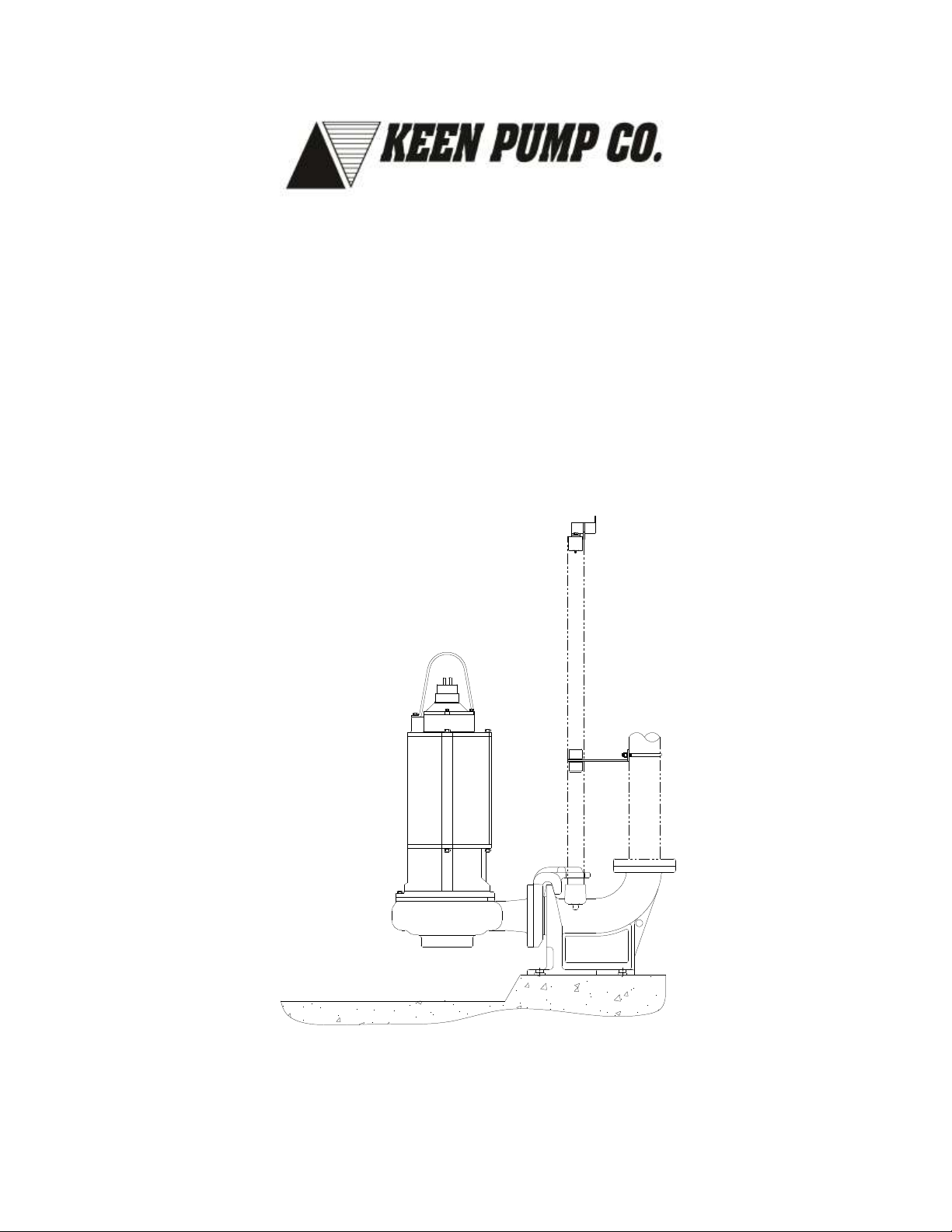
2. Discharge Elbow Installations:
See Pump/rail dimension drawings for the proper location of the discharge elbow on the basin bottom. Either
cast anchor bolts into basin bottom protruding 2” (minimum) from basin floor with lockwashers and nuts
securing, or drill holes for expansion lag screws to secure elbow to basin bottom. Each elbow requires four
anchors (all furnished by others). Each elbow must be level. Length of anchors embedded in concrete varies
with materials used, but must be sufficient to withstand the weight, torque, and thrust loads imposed by the
pump.
3. Discharge Piping (all Supplied by Others):
Install vertical discharge piping modules to elbow using bolts, nuts, lockwashers and gasket. Install remainder
of the sump discharge piping. This typically includes a vertical run of piping appropriately sized and
configured to mate with the vertical discharge piping, a ninety degree elbow, and a horizontal run of piping
approximately sized and configured to mate with the valve box or main piping. Install horizontal run extending
through the wall of basin. Secure vertical run to the vertical discharge piping using the appropriate method
(i.e. flange, weld, gasketed collar coupling) and grout all piping extending through basin walls.
NOTE: If using flanged connections be certain that adequate clearance is provided throughout for
installations of bolts, nuts, lockwashers, and gaskets.
If total run of vertical piping exceeds twelve (16) feet, install a piping brace at the approximate midpoint of the
piping. Secure brace (i.e., U-bolt with angle iron strap and angle iron extensions) to both piping and wall of
basin.
4. Basin Cover(s):
The basin cover for the sump and valve box can either be poured concrete or precast. If Keen Pump-supplied
door and frame assemblies are used, locate the concrete openings with respect to the discharge elbow
mounting studs as shown in the installation drawing data. If the covers are poured, place the door and frame
assembly inside the concrete form and position per installation drawing data. If precast covers are used,
remove anchor straps form frame before installing into covers. If valves are to be inside the wet well, provide
access ways as required for the piping and valves. Access ways must be covered and secured with tamper-
proof hardware (by others).
5. Guide Rail Installation:
Install the guide rails by attaching the lower end of the guide rail to the plugs on the topside of the discharge
elbow. At the top of the guide rails, plumb and then fasten the guide rail to the door and frame assembly via
the upper guide rail bracket.
6. Intermediate Guide Rail Bracing:
Sump depth of 16’ 0” and greater require intermediate guide rail bracing. The braces mount on the vertical
discharge pipes with U-bolts which are sized according to the discharge pipe size. The number of guide rail
braces required is as follows:
PUMP INSTALLATION

5
Sump Depths:
16’ 0” – 30’ 0” – 1 Guide rail brace required
30-‘0” – 45’0” – 2 Guide rail braces required
7. Exterior Piping;
Install the inlet hub(s) in the side of basin and install inlet piping in the hub and grout, or install inlet pipe(s)
directly into basin and grout. Install drain pipe form valve box (if required) to basin. Slope pipe to give proper
drainage to basin. Install vent piping in side of basin (if required). Extend piping to a proper elevation above
grade (as required by plans and specifications and/or local codes). All piping furnished by others. See
Installation drawing Data for typical piping arrangement.
8. Pump and Sealing Flange:
Assemble the Sealing Flange to the pump discharge flange using a gasket between the two.
9. Pump Installation:
Check all piping braces and supports for proper installation and tightness. Attach one end of the lifting cable
or chain to the pump eyebolts and the other to hook supplied on the inside of the hatch frame.
Lower the pump into the basin locating rail guide between the two guide rails. Attach the upper end of lifting
assembly to a hook provided on the inside of hatch frame.
10. Float Switches
Mount the float switch mounting bracket to the door and frame assembly using 3/8–16UNC stainless steel
screws. Include a dielectric gasket (by others) between dissimilar metals to avoid galvanic corrosion. Allow
excess float cable to loop over mounting bracket. The sump level is controlled by Keen Pump float switch
controls. The float is held in position in the sump by a weight attached to the power cord above the float. The
cord supports the float and is adjusted for height from the surface. Duplex systems use three controls: one at
both pumps off, one set at one pump on, and one set for both pumps on. Pumps alternate operation on each
successive cycle with a Keen Pump Panel. The alarm level is usually set above the override level as it is
possible for one pump to fail and the other to operate on the override level with the sump level never reaching
the alarm level. Do not let floats rest against basin wall or bottom, or entangle with each other or pump(s).
11. Panel Mounted Remote from Basin:
If the Control Panel is remotely located, install conduit coupling through basin wall. Screw protective bushing
from inside basin into coupling (all furnished by others), Make connections outside station using wiring,
conduit seals (potted) and conduit to remotely located Panel (conduit and seals not furnished). Insert the
power and sensor cords through the coupling provided with the bushing. Grout in coupling goes through sump
wall (by others). When installing pump power cords, make certain that cords do not rub against pump or on
bottom of basin. Shorten cords to suit the installation.

6
WARNING: Before handling these pumps and controls, always disconnect the power first. Do not
smoke or use sparkable electrical devices or flames in a septic (gaseous) or possible septic basin.
See Pump Installation and Service Manual for submersible pump operation on starting system. Clean all trash
and sticks from basin and connect pump to piping.
Removing Pump from Basin for Servicing:
WARNING: Before handling these pumps and controls, always disconnect the power first. Do not
smoke or use sparkable electrical devices or flames in a septic (gaseous) or possible septic basin.
To remove a pump from a standard installation the power to the control panel is first turned off. Close the plug
valve. Disconnect the power cords and sensor cords in the control panel from their terminals. Lift out the
pump from the basin by means of the chain or cable. Disconnect the flexible conduit, power and sensor cords
from the control panel. Pull the pump cord down through the pipe coupling while holding the cord on the
underside of the basin cover so the cords do no fall into the basin. For installing the pump, reverse the above
procedure.
Remove Float Controls for Replacement:
To remove a float for replacement from a standard installation the power is first turned off to the control panel.
Disconnect the float leads from the terminals in the control panel. Disconnect the flexible conduit from the
control panel. Remove the flexible conduit and the float control leads from the control panel. Remove flexible
conduit from potting head. Break out potting from the potting head and remove the float wire. Remove float
cord from the float cord mounting bracket and remove float from basin. Replace float by reversing removal
procedure. Repot the leads in the potting head according to N.E.C. and/or local codes.
PUMP OPERATIONS
PUMP MAINTENANCE

7
WARNING: Before handling these pumps and controls, always disconnect the power first. Do not
smoke or use sparkable electrical devices or flames in a septic (gaseous) or possible septic basin.
The following is a list of common problems and possible solutions. Refer to Pump Installation and Service
Manual for any necessary adjusting, dismantling or repair work required on the pump.
Pump runs but does not pump down the basin with the selector switch on either Hand or Automatic
position.
1. Impeller may be clogged. Amperage higher than nameplate will indicate this.
2. Pump rotation may be wrong. Reversing any two line leads on three phase pumps will reverse the
rotation.
3. Discharge plug valve may be closed.
4. Plugging anywhere from impeller to sealing flange. This is evident if no water runs out of sealing
flange after raising the pump. Pull the pump from the basin to find the clog.
5. Plugging beyond the sealing flange. This is evident if water does run out when pump is operating
when disconnecting the sealing flange form the discharge elbow. Remove the check valve, clean out
cover and plug valve and other piping, if necessary, inside valve box to find clog. Reassemble all
valves and piping. If the basin is still not pumped down after the pump is lowered again and the
sealing flange is reconnected, proceed in a logical manner to locate and clear the plugging.
6. Discharge head may be too high. Check elevation against design point of pump.
7. Improper discharge flow. Check for correct impeller size and proper voltage.
8. Check for possible broken or clogged forced main.
Basin level is pumped down with selector switch on Hand position, but is not pumped down with
selector switch on Automatic position.
1. Floats are not hanging free in the basin or are covered with debris. Pump the level down with the
selector switch on hand, so that the floats can be observed. Relocate and clean all floats as
necessary.
2. If this is a new installation and original start-up, the floats may be miswired into the control panel.
Recheck the wiring diagrams and schematics in the panel. If the start and stop floats are hooked in
reverse, the pump will short cycle on and off and will not pump the level down.
3. Floats or alternator are malfunctioning. Pull the floats out of the basin, clean them and lay then on the
ground. Lift up the stop (lower) float in the left hand, the start (upper) float in the right hand and with
the floats hanging free, turn selector switch to Automatic. Lower the left hand until the float hits the
ground and lies on its side. Nothing should happen. After lowering the right hand in the same manner,
the pump should start. When raising the right hand to suspend continue to run. The pump should stop
when raising the left hand to suspend the float. If this procedure does not cause the pump to operate
as described, either order new float switches or replace alternator relay.
PUMP TROUBLESHOOTING

8
KEEN PUMP COMPANY, INC.
471 US Hwy 250 East, Ashland, OH 44805
Phone: 419-207-9400 Fax: 419-207-8031
Limited 3 –Year Warranty
During the time periods and subject to the conditions hereinafter set forth, Keen Pump will repair or replace to
the original user or consumer, any portion of your new Keen product which proves defective due to defective
materials or workmanship of Keen Pump. Contact your closest authorized Keen Pump representative or
distributor for warranty service. At all times, Keen Pump shall have and possess the sole right and option to
determine whether to repair or replace defective equipment, parts or components. Damage caused by acts of
GOD or conditions beyond the control of Keen Pump is not covered by this warranty.
WARRANTY PERIOD:
36 months from date of manufacture.
Start-up reports are required to support warranty claims. Warranty effective only if Keen Pump supplied or
authorized control panels are used. Single phase pumps must utilize Keen Pump supplied start components.
THIS WARRANTY WILL NOT APPLY:
(1) To defects or malfunctions resulting from failure to properly install, operate or maintained the product
in accordance with printed instructions provided.
(2) To failures resulting from abuse, accident or negligence.
(3) To normal maintenance services and the parts used in conjunction with such service.
(4) To products which are not installed in accordance with applicable local codes, ordinances and good trade
practices.
(5) The product is used for purposes other than for what is was designed and manufactured.
(6) If 3 phase motors are installed on a single phase power supply using a phase converter or if 3 phase
power is supplied by only two transformers, making an open Delta system.
WARRANTY EXCLUSIONS:
Keen Pump specifically disclaims the implied warranties of merchantability and fitness for a particular purpose
after the termination of the warranty period set forth herein. No warranties or representations at any time made
by any representatives of Keen Pump shall vary or expand the provision hereof.
LIABILITY LIMITATION:
In no event shall Keen Pump be liable or responsible for consequential, incidental or special damages resulting
from or related in any manner to any Keen Pump product or parts thereof. Personal injury and/or property
damage may result from improper installation. Keen Pump disclaims all liability, including liability under this
warranty, for improper installation. Keen Pump recommends following the instructions in the installation
manual. When in doubt, consult a professional. Some states do no allow the exclusion or limitation of incidental
or consequential damages, so the above limitation or exclusion may not apply to you.
LABOR, ETC., COSTS:
Keen Pump shall in no event be responsible or liable for the cost of field labor or other charges incurred by any
customer in removing and/or reaffixing any Keen Pump product, part or component thereof or any temporary
pumping of other equipment.
RETURNED OR REPLACED COMPONENTS:
Any item to be replaced under this Warranty must be returned to Keen Pump, or such other place as Keen Pump
may designate, freight prepaid.
This warranty gives you specific legal rights and other rights which may vary from state to state.
In the absence of suitable proof of this purchase date, the effective date of this warranty will be based upon the
date of manufacture. Example: 0105 = Month-Year = January, 2005. P/N O&M-KL RAILS
Table of contents
Other Keen Pump Water Pump manuals