6. Insert ceramic seal firmly into the impeller as shown in figure (9).
7. Place Impeller over the engine shaft and turn it in a clockwise direction to at-
tach to the engine shaft.
8. Insert “O” ring (104) gasket and press into slot firmly
9. Place Pump Housing onto back plate (Figure 11) and secure with 4 Pump
Housing Mounting Bolts and 4 Pump Housing Mounting washers (HB &HW). Set
bolt and washers loosely though back Plate into Pump Housing. Make sure align-
ment is correct and tighten firmly. Double check to see that the Pump back plate
contains the ”O” Ring Washer (Fig 10) and is in its proper position. Care must be
taken not to overtighten as the bolts in the housing as the threads are aluminum
and could become easily stripped. O Ring is not shown in above diagram.
Compressor Pulley In-
stalled on engine im-
peller Shaft Bushing
Impeller
Shaft Pulley
Figure #9
Figure #8
Threaded
Engine shaft hole
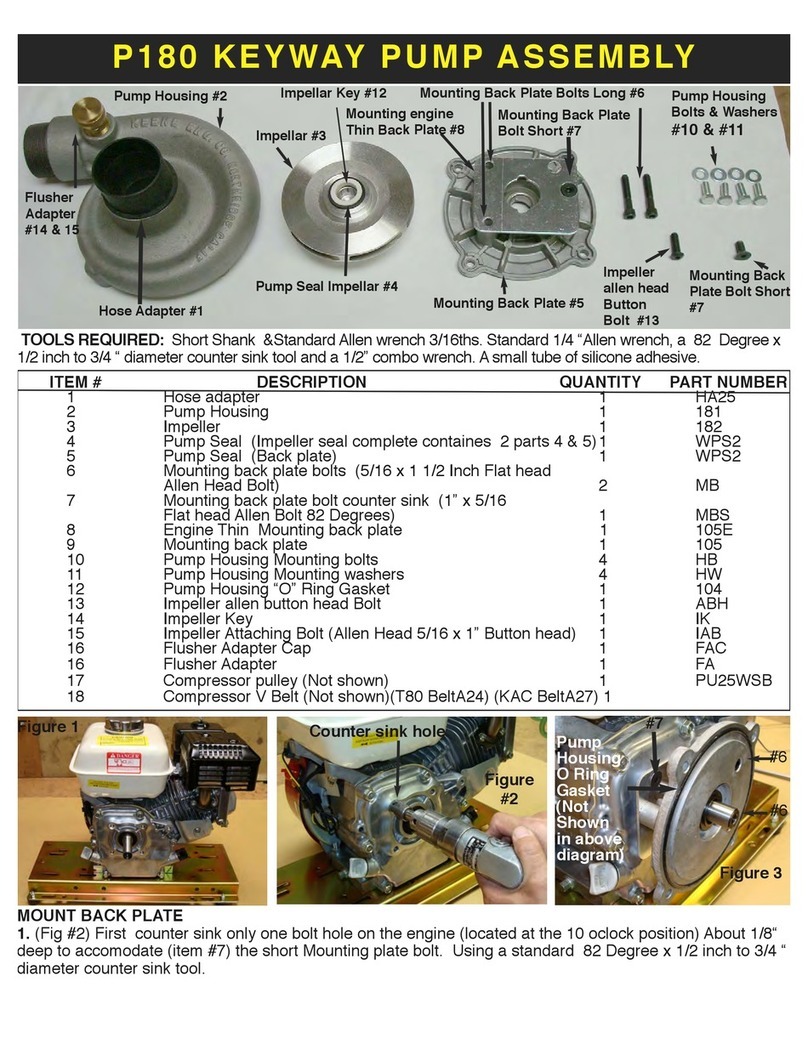
2. Before mounting the back plate assembly (105 &105E) to engine, the BackPlate Pump Seal (5) must be
pressed flush into center hole of the back of the Pump Back Plate (105) before attaching Engine Back Plate
(105E) Use a small dab silicone adhesive around edge of the hole to prevent leakage.
3. Attach Engine Mounting Back Plate (105E) to the Pump Mounting Back Plate (105) by Attaching the
counter sunk back plate bolt (MBL) into the pump back plate (105) and tighen securely.
4. Before mounting back plate assembly (105 &105E) to the engine slip the impeller shaft bushing(ISB) onto
the engine shaft as shown in figure # 6 and also place the compressor pulley over the bushing if a compres-
sor is being used (14) and tighen set screw once placed on engine shaft, also place compresor V belt (A24)
over the shaft pulley. (Ask for the size of V belt to match model of compressor being used)
5. To align mounting plate to engine, insert and tighten the 2 Mounting back plate long bolts (#6) firmly to
engine (see fig #10). Note: The Compressor V Belt is not shown in the above diagram.
Figure
#6
Figure #7
4 bolts &
Washers
Figure #10
Figure #11
Mount-
ing
Plate
bolts (6)
Ceramic Seal (4) O Ring Gasket
Impeller Shaft
Bushing
ADDITIONAL SPECIAL SEAL INSTALLATION INSTRUCTIONS:
1. Before installing the mounting plate to the engine, the spring portion of the water pump seal must be in-
stalled. Place this portion of the seal into the center of the mounting plate, with the use of a light hammer
and or blunt instrument and or a seal setting tool. Tap the perimeter metal portion of the seal to set the seal
into position. Care must be taken to avoid contact with the carbon portion of the seal. A small amount of Sili-
cone Rubber Cement placed in this section will insure a water tight seal. Insert the mounting bolts into the
mounting plate. Tighten the bolts evenly so as to prevent mis-alignment.
2. Fit "O" Ring gasket into "O" slot on the front face of the mounting plate, making sure that it is properly
seated. Place the ceramic portion of the water pump seal into the center of the impeller firmly, using the heal
of your hand to insure a proper fit. The ceramic surface of the seal must be facing outwards. Thread the im-
peller onto the engine shaft by turning it gently in a clockwise rotation, taking care to avoid damage to the
threads on the impeller.
3. Attach the outer housing to the mounting plate, using the 4 housing bolts and washers. Tighten the hous-
ing bolts evenly to ensure proper tension and alignment. Extreme care must be taken to prevent over tight-
ening of the bolts. Too much torque will damage the threads in the outer housing.


