Keiser KP330 User manual

KP330
User Manual
Electric Airless Sprayer
Important Safety Instructions. Read all warnings and instructions
in this manual. Save these instruction s.

WARNING
GROUNDING
Improper installation or alteration of grounding plug results in risk of electric shock,
fire or explosion that could cause serious injury or death.
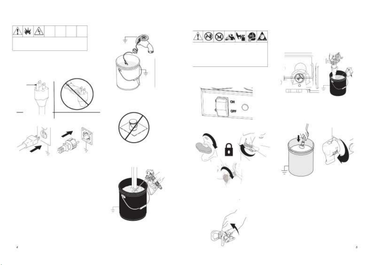
When repair or change the wire, do not p lug the groun d wire into a flat outlet.
Do not alter groun d prong or use adapter.
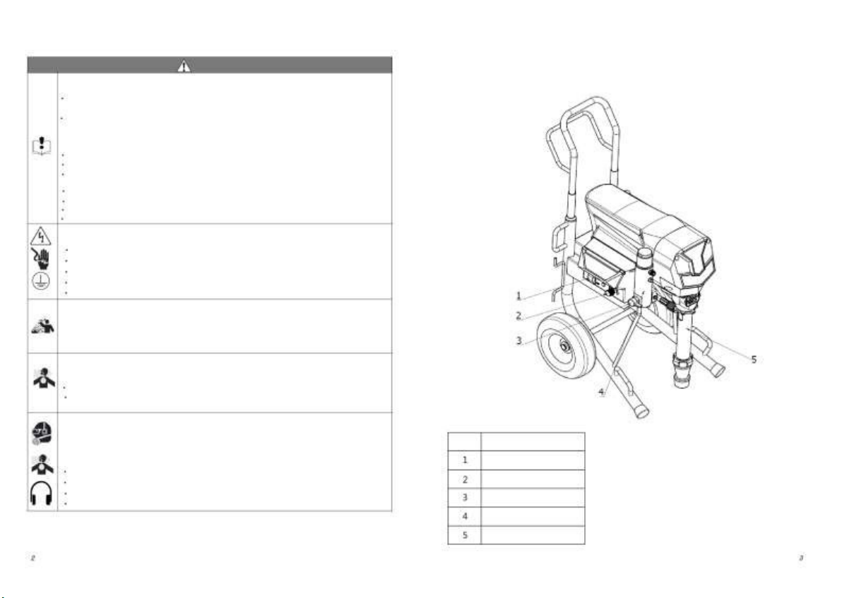
The product require a 220V, 50/60 Hz circuit with a grou nding receptacle.
You may use a 3-wire, 2.5mm2(12 AWG) (minimum).
Long lengths of cords redu ce sprayer performance.
If you are not understand the statement of groun ding, please seek help of electrician.
FIRE AND EXPLOSION HAZARD
Flammable fumes, such as solvent and p aint fumes, in work area can ignite or explode.
To help prevent fire and explo sion:
Use equipment only in well ventilated area.
Eliminate all ignition so urces; such as p ilot lights, cigarettes, portable electric lamps,
and p lastic drop cloths (potential static arc).
Sprayer generates sparks. When flammable liquid is used in or near the sprayer or for
flushing or cleaning, keep sprayer at least 20 feet (6 m) away from explosive vapors.
Keep work area free of debris, including solvent, rags, and gasoline.
Do not plug or un plug power cords or turn lights on or off when flammable fumes are
present.
Groun d equipment and conductive ob jects in work area. Read Grou nding instructions.
If there is static sparking or you feel a shock, stop operation immediately.Do not use
equipment until you identify and correct the problem.
Keep a fire extinguisher in the work area.
INJECTION HAZARD
High p ressure fluid from gun, hose leaks, or rup tured components will pierce skin. This
may look like just a cut, bu t it is a serious injury that can result in amputation. Get
immediate surgical treatment.
Do not point the gun at anyone or at any part of the body.
Do not put your hand over the spray tip.
Do not sto p or deflect leaks with your hand, bo dy, glove or rag.
Do not spray without tip gu ard and trig ger guard installed.
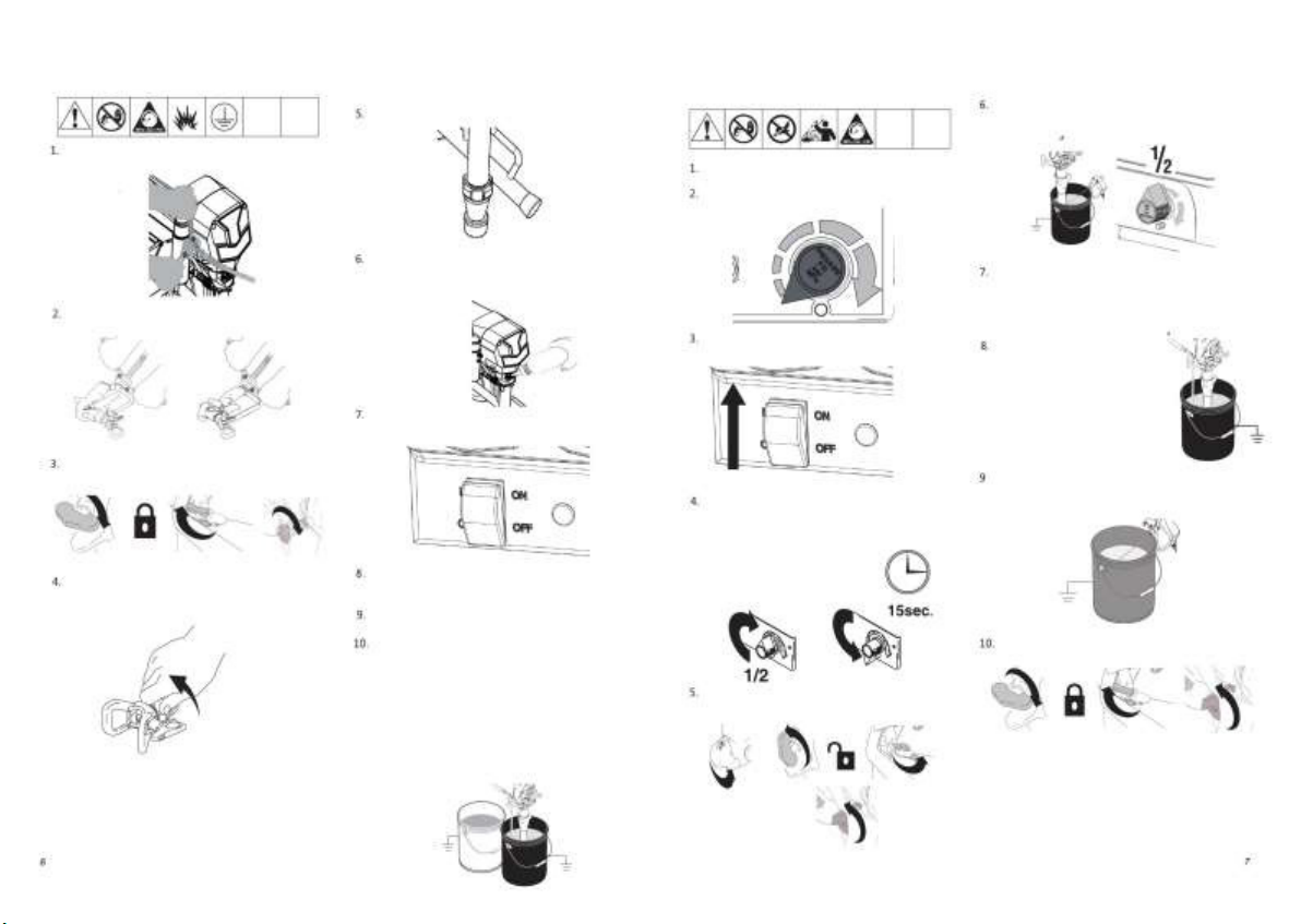
Engage trigg er lock when not spraying.
Follo w Pressure Relief Procedure in this manual, when yo u stop sprayin g and before
cleaning, checking, or servicing equipment.

Compone nt Ide ntification
KP330 –Electric Piston Airless Sprayer
WARNING
EQUIPMENT MISUSE HAZARD
Misuse can cause death or serious inju ry.
Do not exceed the maximum working pressure o r temperature rating of the lowest
rated system component. Read Technical Data in all equipment manuals.
Use fluids and solvents that are compatible with equip ment wetted parts. Read
Technical Data in all equip ment manuals. Read fluid and solvent manufacturer's
warnings.For complete information about your material, request MSDS from
distributor or retailer.
Check equip ment d aily. Repair or replace worn or damaged parts immediately.
Do not alter or mod ify equipment.
Route hoses and cables away from traffic areas, sharp edges, moving parts, and hot
surfaces.
Do not kink or overbend h oses or use hoses to pull equipment.
Comply with all applicable safety regulations.
Keep children and animals away from work area.
Do not operate the un it when fatigued or under the influence of drugs or alcohol.
ELECTRIC SHOCK HAZARD
Improper groundin g, setup, or usage of the system can cause electric sh ock.
Turn off and disconnect p ower cord before servicing equipment.
Use only groun ded electrical outlets.
Use only 3-wire extension cords.
Ensure ground prongs are intact on sprayer and extension cords.
Do not expose to rain. Store indoors.
PRESSURIZED ALUMINUM PARTS HAZARD
Do not use 1,1,1 -trichloroethane, methylene chloride, and/or other halog enated
hydrocarbon solvents or fluids containing such solvents in pressurized aluminum
equipment. Such use can cause serious chemcal reaction and equ ipment rupture,
and result in death, serious injury, and/or prop erty damage.
TOXIC FLUID OR FUMES HAZARD
Toxic fluids or fumes can cause serious injury or death if splashed in the eyes or on
skin, inhaled, or swallowed.
Read MSDS’s to know the specific hazards of the fluids you are using.
Store hazardous fluid in approved containers and dispose of it according to
applicable guidelines.
PERSONAL PROTECTIVE EQUIPMENT
You must wear app ropriate protective equipment when operating , servicing, or when in
the operating area o f the equipment to help protect you from serious injury, including
eye injury, inhalation of toxic fumes, burns, and hearin g loss. This equip ment includes,
but is not limited to:
Protective eye wear
Clothing and respirator as recommended by the fluid and solvent manufacturer
Gloves
Hearing protection
FN
Component
ON/OFF switch
Pressure control
Prime valve
Manifold
Pump

Grounding
Metal pail:
Improper installation or alteration of grounding plug
results in risk of electric shock, fire or explosion
that could cause serious injury or death.
Pre ssure Re lief Proce dure
4.Turn pressure to lowest setting. Hold gun
to side of ground ed metal flushin g bucket.
Trigger gu n to relieve pressure, turn prime
valve do wn.
Electric:
Groun ding Plug
To reduce risk of injury from injection, follo w
this procedure whenever you are instructed
to relieve pressure, stop spraying, service
equipment or install or clean spray tip.
Read warnings.
1. Turn power switch OFF and unplug power cord.
waiting at least 7 seconds until the power off.
Attached ground wire to pail and true earth grou nd.
5.Put drain tube in to pail. Leave
Spray-Prime/Drain valve in the PRIME/DRAIN
positio n unitl you are ready to spray again.
2.Engage gun trigger lock if until is b eing shut down
or left unattended
Don't change th e plug
Do not put the metal pail in a wood or something
nonconductin
Plug power supply cord into a properly grounded
electrical outlet.
Caution:
1.It requires a 22 0V, 50 /60 Hz, 10A- 16A AC
circuit with a groun ding receptacle.
2.Confirm without damaged of wire before using.
3.Use a 3-wire, 2.5mm2(12 AWG) (minimum).
Long lengths reduce sprayer performance.
4.Do not alter ground prong or use adapter.
Keep grounding when clean up and pressure relief.
6.If you suspect the spray tip or hose is clogged
3.Remov e the tip gu ard and tip.
or that pressure has no t been fully relieved after
following the steps abov e, VERY SLOWLY loosen
tip guard retaining n ut or hose end coupling to
relieve pressure gradually, then loosen completely.
Clear hose o r tip obstruction.

Setup/Installation
Ch eck the intaken of pump for clogs and debris.
Co nnect KP330 airless hose, to sprayer.
Tighten securely.
Startup
Hold gun against groun ded metal flushing pail.
Trigger sure to 1/2. Flush 1minute.
Do the pressure relif. page 5.
Turn p ressure control to lowest pressure.
Fill throat packing nut with TSL to p revent premature
packing wear. Do this each time you spray.
Co nnect other end of hose to gun. Tighten securely.
Turn power on.
Inspect for leaks. Do no t stop leaks with hand or
a rag! If leaks o ccur, do Pressure Relief. Tighten
fittings. Do Startup, 1. - 5. If no leaks, proceed
to 8.
Place pump in paint pail.
Turn power OFF.
Engage gun trigger lock.
Increase pressure 1/2 to start motor
and allow fluid tocirculate throu gh
drain tube for 15 seconds; turn
pressure down.
Remove tip guard.
Plug power supply cord into a properly grounded
electrical outlet.
Turn prime valve down.
Place pump set in grounded metal pail
partially filled with flushing fluid. Attach ground
wire to pail and to true earth ground. Do 1. - 5.
of Startup to flush out storage oil shipped in
sprayer. Use water to flush water-base paint
and mineral spirits to flush o il-base paint and
sto rage oil.
Set gu n safety ON. Assemble tip and guard.
Trigger gu n again into flushing pail until
paint appears. Move gun to paint p ail and
trigger for 20 seconds.
Turn prime valve horizontal.Take spray
gun trigger safety OFF.

Cl eanup
Assemble tip and guard
Spray
1. Do Pressure Relief, steps 1 - 4(page 5). Remo ve
sip hon tube set from paint and p lace in flushing fluid.
NOTE: Use water for water base paint and mineral
spirits for oil base p aint.
6. Raise sipho n tube above flushing fluid and run
sprayer for 1 5 to 30 seconds to drain flu id.
Relief pressure, page 5.
Insert tip gasket and seal kit.
Spray test pattern. Adjust pressure to elimin-
ate heavy edg es. Use smaller tip size if pres-
sure adjustment can no t eliminate heavy edges. 2. Turn p o wer ON. Turn prime valve horizontal.
7. Close drain valve. Trigger gun into flushing pail
to purge fluid from hose. Tu rn power OFF.
8. Open prime v alve.Unplug sprayer.
Insert Switch tip.
Hold gun perpendicular, 10 -12in. from surface.
Spray back and forth. Overlap by 50%. Trigger
gun after moving and release before stopping.
3. Increase pressure to 1/2.Hold g un against paint pail.
Take trigger safety OFF.Trigger gun until flushing
fluid appears
9. Remo ve filters from gun and sprayer, if installed.
Clean and inspect. Install filters.
Cl ear C log
Screw assembly onto gun. Tigh ten.
Release trigger, put safety ON. Rotate Swi-
tchTip. Take safety OFF. Trigger gun to
clear clog. Never point gun at yo ur h and or
into a rag!
4. Move gun to wastepail, hold gun against pail, trigger
gun to thorough ly flush system.Release trigger and
put trigger safety ON.
10. If flushing with water, flu sh again with mineral
spirits, or Pump Armor, to leave a protective
coating to prevent freezing or corrosion.
Put safety ON. Return SwitchTip to original
positio n. Take safety OFF and continue
spraying.
5. Turn prime valve do wn and allow flushing fluid to
circulate for 15 second s to clean drain tub e.
11. Wipe sprayer, hose and gun with a rag soaked
in water or mineral spirits.

Digital Tracki ng System
Control Board Re placement
Removal
KP330
Operation Main Menu
1.Turn pressure to lowest setting. Trigger gun to
relieve p ressure. Tu rn prime valve down to DRAIN
positio n.
4. Press DTS butto n again and the screen displays
motor temperature.Picture below disp lays moto r
temperature 30 degree Celsiu s
Relieve pressure, page 5. wait 5 minutes
before servicing .
1.Remov e 4 screws and cover.
2.Discon nect display, po tentiometer connector.
Also disconnect two red power leads from
ON/OFF switch.
3.Discon nect transducer connector from motor
control board.
4.Use plus driver to loosen the motor conn ector,
Connector sequence is yellow, green and blue.
5.Remov e 6 screws from control b oard.
2. Press DTS butto n once to change to pressure
unit PSI.Picture below displays 3300PSI.
5. Press DTS butto n again to change to pressure
unit BAR.Picture below displays 230 bar.
3.Install motor control board with six screws.
2.Apply small amount of thermal compo und
to shaded component areas on rear of motor
control board.
Installation
Torque to 17 in-lb (1N·m).
1.Use acetone or similar cleanser to clean sweep
thermal compound from shaded component
areas on rear of motor control board.
3. Press DTS butto n again and the screen displays
the total motor run hours.Picture below displays
total motor run 8 h ours.
10
11

Drive Housin g Replacement
CAUTION
Do not drop gear cluster when removing
drive ho using (3). Gear cluster may stay
engaged in motor front end bell or drive
housing.
Installation
Disassembly
Make sure gear (3 ) and thrust washers (15,16,17,
18) are in place (16/17 are copper thrust washers)
Brush g rease onto gear teeth.
1.Push drive h ousin g(3) into gear box(20), and fix it
with five screws (13). Torque to 21 –23 N·m.
2.Install connecting rod(4) and bearing housing
(19) to drive housing(3).
3.Install fou r screws(14 ).Torque to 2 1 –23 N·m.
4.Install pump (41); Displacement Pump
Replacement ,page 14.
5.Install pump rod cover (9) with screw (8).
6.Install fron t cover(12) with screw(11).
Relieve pressure, page 5.
1.Remov e screw (11)and front cover (12).
2.Remov e screw (8)and pump rod cover (9).
3.Remov e pump (7); Displacement Pump
Replacement, page 17
4.Remov e fou r screw (14 ),connecting
rod (4)and b earing housing (19).
5.Remov e screw (13 ) and pull drive housing
(3)off case(20).
12
13

Coupling Replacement
FOR KP330
Motor Re place ment
FOR KP330
Removal
Installation
Removal
Installation
1.Replace the motor,tig hten the 4 screws.
1.Push coup ling toward input shaft till input shaft
surface,tighten screws on coup ling.
1.Relieve pressure,page 5
2.Remov e screw(1) and motor cover(2)
3.Remov e screws(21)(22 )
4.Remov e screws on one coupling part and
coupling
5.Pull out coupling
6.Remov e screws on other couplin g part of
input shaft
7.Pull out coupling
2.Push input shaft into motor shaft.Measure the
depth 35 .5mm-35 .7 mm with vern ier caliper.The
measurement position marked as picture,
1.Relieve pressure, page 5.
2.Remov e coupling,page 12.
3.Remov e the screws on the control
board case
4.Discon nect all motor connnectors from
con trol b oard
5.Remov e the fan (23)
6.Remov e the screws (24)
7.Remov e the motor (25)
2.Install the coupling.page 12.
3.Connect the moto r assembly with drive housing,
make sure two coup ling p arts are in place.
4.Tighten the drive hou sing with four screws (2 2).
5.Tighten the drive hou sing with two screws (21 ).
6. Connect moto r leads from up to down yellow,
green,blue.
7.Tighten control broad cover(27 ) with screws(26)
8.install the motor cover(2).
9.Tighten th e screw(1 )
3.Connect the motor assembly with drive housing,
make sure two coupling parts are in place.
4.Tighten four screws(22) with 21 -23 Nm
5.Tighten two screws(21) with 21 -23 Nm
6.Install back cov er
7.Tighten th ree screws(1)
21
14
15

Motor Re place ment
FOR KP330
Displace ment Pump Replacement
Caution
If the pump jam nut lo osens during operation,
threads of the drive housing will be damaged
Installation
Removal
Installation
Removal
Relieve pressure,page 5
1.Remov e screw(1) and motor cover(2)
2.Remov e the screws and con trol board(27)
3.Discon nect all motor connnectors from
control board
4.Remov e the fan (23)
5.Remov e the screws (28) and nuts(29)
6.Remov e the screws (24) and mo tor(25)
1.Push motor on to motor frame and in stall with
screws (24). Torque to 21–23 N·m.
2.Tighten mo tor on cart frame with four screws
(28) and nuts (29).Torque to(21 –23 N·m).
3.Tighten th e fan(23 )
4.Connect mo tor leads from up to down yello w,
blue,green.
5.Tighten control broad cover(27 ) with screws(26)
6.Install th e motor cover(2).
7.Tighten th e screw(1 )
1.Flush pu mp.
2.Relieve pressure,page 5.
3.Remov e screws(28),
slid p ump rod shield left(29).
If pump pin works loose, parts cou ld break off
due to force of pumping action . Parts could
project th rough the air and result in serious
injury or property damage.
1.Extend pump piston rod 40mm.
2.Install pump pin.Verify retaining spring is in
groove of connecting rod.
3.Push pump up un til pump threads engage.
4.Screw in pump until threads are flush with
drive housing opening. Align pump outlet to back.
4.Turn slowly pressure con trol knob clockwise
to make motor work slo wly until pump pin(44)
is in position to be removed. Turn power switch
OFF and u nplug po wer cord. retain ring(43)
and push pu mp pin out.
5.Install the hose(32)
6.Screw jam nut (33 ) up onto pump until nut
sto ps. Tighten jam nut by hand, then tap 1/8
to 1/4 turn with a 0.5k g (maximum) hammer to
approx imately 102 Nm.
7.Fill packin g nut with lubricating oil 5 -6 drops.
5.Remov e the hose(32).
6.Loosen pump jam nut(33),
unscrew and remove pump.
16
17
Table of contents