Keith Products TR-134 User manual


Products, INC.
TR-134 System Service Manual
January 8, 2010
Page iv
LIST OF EFFECTIVE PAGES
SECTION PAGE DATE
Title i January 8, 2010
Record of Revisions ii January 8, 2010
iii January 8, 2010
List of Effective Pages iv January 8, 2010
Table of Contents v January 8, 2010
Introduction 1 September 15, 1995
Air Conditioning System Description 2 September 15, 1995
3 September 15, 1995
4 March 6, 2002
5 September 15, 1995
Refrigerant Servicing 6 August 21, 2006
7 August 21, 2006
8 August 21, 2006
9 August 21, 2006
10 January 8, 2010
11 January 8, 2010
12 January 8, 2010
General Servicing 13 August 21, 2006
14 August 21, 2006
15 January 8, 2010
16 August 21, 2006
17 August 21, 2006
18 August 21, 2006
19 August 21, 2006
Troubleshooting 20 August 21, 2006
21 August 21, 2006
22 August 21, 2006
23 August 21, 2006
24 August 21, 2006
25 August 21, 2006
Checks 26 August 21, 2006
27 January 8, 2010
28 January 8, 2010

Products, INC.
TR-134 System Service Manual
January 8, 2010
Page v
TABLE OF CONTENTS
SUBJECT PAGE
Title i
Record of Revisions ii
Table of Contents iii
Introduction
1
AIR CONDITIONING SYSTEM DESCRIPTION
1. Vapor Cycle System Description 2
2. Electrical Driven Compressor Systems 4
3. Engine Driven Compressor Systems 5
REFRIGERANT SERVICING
1. General 6
2. Discharging System 7
3. Evacuating System 8
4. Charging System 9
5. Flushing System 10
GENERAL SERVICING
1. General 13
2. Inspection Intervals 13
3. Plumbing System Maintenance Procedures 14
4. Coil Cleaning Maintenance Procedure 16
5. Expansion Valve Removal & Installation 17
6. Compressor Maintenance Procedures 19
TROUBLESHOOTING
1. General 20
2. Air Conditioning System Diagnosis Chart 21
3. Air Conditioning System Troubleshooting 22
4. Compressor Troubleshooting 25
CHECKS
1. General 26
2. Refrigerant Level Check 26
3. Refrigerant System Leakage Check 27
4. Compressor Oil Level Check 27

Products, INC.
TR-134 System Service Manual
Sep 15/95
Page 1
INTRODUCTION
1. PURPOSE
The purpose of this System Service Manual is to provide detailed instructions for
the servicing, troubleshooting, checking and maintaining of the Keith Products, INC.
air conditioning systems using R134a refrigerant. It is intended to be used for all
Keith Products air conditioning systems using R134a refrigerant that do not contain
separate maintenance instructions. The System Service Manual supplements the
Maintenance Manual supplied by Keith Products for your particular aircraft type.
For the latest revision of this document, please visit www.keithproducts.com.
2. SCOPE
The scope of the System Service Manual provides the maintenance technician with
detailed information covering:
- Overall system level description and theory of operation.
- Component level description and theory of operation.
- System level checking and troubleshooting procedures.
- Procedures for servicing the air conditioning system refrigerant.
- The identification of special equipment to accomplish the specific tasks.
3. ARRANGEMENT
This System Service Manual is arranged similar to Air Transport Association (ATA)
Specification 100 and provides general servicing and maintenance instructions .
4. GLOSSARY
Nonstandard abbreviations and symbols used in the Maintenance Manual are
described below.
Abbreviations:
A/C - Air Conditioning
A/R - As Required
Assy - Assembly
Comm. Avail. - Commercially Available
Evap - Evaporator
Gnd - Ground
GPU - Ground Power Unit
SW - Switch
VDC - Volts Direct Current

Products, INC.
TR-134 System Service Manual
Sep 15/95
Page 2
AIR CONDITIONING SYSTEM - SYSTEM DESCRIPTION
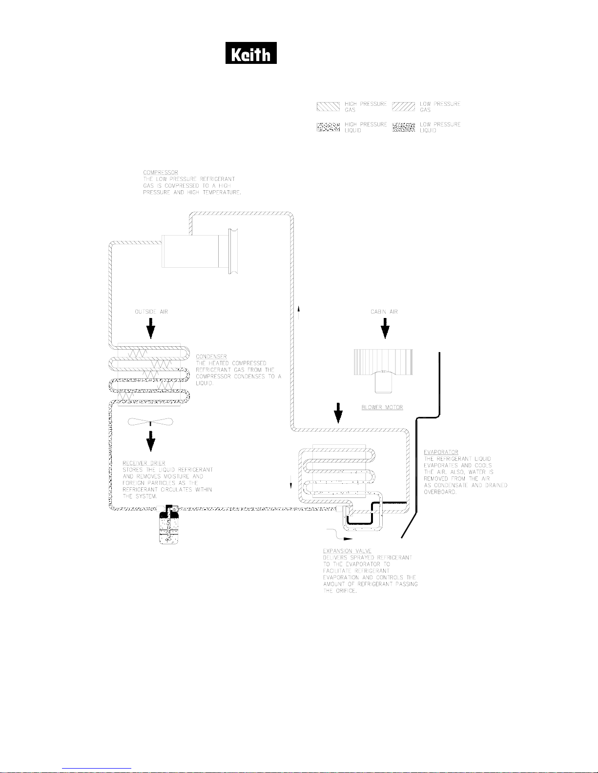
1. VAPOR CYCLE SYSTEM DESCRIPTION
The Keith Products vapor cycle air conditioning system uses liquid refrigerant
R134a to cool the aircraft cabin. The major components for the R134a air
conditioning system consists of a receiver/dryer, expansion valve, evaporator,
compressor and condenser to cool the aircraft cabin. Figure 1 shows an
operational schematic of the air conditioning system.
The receiver/drier stores liquid R134a refrigerant under pressure. The drier portion
of the assembly removes any traces of moisture that may have accumulated in the
system. Liquid refrigerant flows from the receiver drier through the expansion valve
where the refrigerant pressure is reduced, allowing it to spray into the evaporator.
At the same time, a blower driven by an electric motor passes air over the
evaporator. This air is cooled since heat is removed from the air by the evaporation
of the refrigerant in the evaporator. The evaporator produces water due to
condensation. This water drains overboard through a line attached to the
evaporator cover.
The refrigerant leaves the evaporator as a gas. This gas is pumped by the
compressor, raising its pressure and temperature. This high temperature gas then
flows to the condenser. Cooling air, driven by another electric blower motor,
passes over the condenser, cooling and therefore condensing the refrigerant to a
liquid. The liquid refrigerant then enters the receiver/drier, repeating the process.
The plumbing which connects the compressor, condenser and the evaporators,
consists of rubber based hoses with a nylon barrier. The fittings are permanently
swaged onto the hoses. Some systems that have been converted from R12 to
R134a refrigerant use Barb Lok hose fittings. Fittings are either "o-ring" type or
use flared connections. Sealant is used on the fitting mating surfaces to prevent
refrigerant leaks. Two R134a service valves are sized differently to avoid incorrect
cross-connecting when gaining access to the plumbing for system recharging.
The compressor on Keith Products air conditioning systems is driven either by an
electrical motor, or by the engine. Listed below is a more detailed description of
electric and engine driven compressor systems.

Products, INC.
TR-134 System Service Manual
Sep 15/95
Page 3
Figure 1. Air Conditioning Vapor Cycle System

Products, INC.
TR-134 System Service Manual
March 6/02
Page 4
2. ELECTRICAL DRIVEN COMPRESSOR SYSTEMS
Electrically operated systems use the aircraft electrical system and are operable in
most normal flight modes. Air conditioning may be operated with ground external
power or the aircraft electrical system providing voltage to the proper buss.
The compressor and condenser are manufactured on an assembly pallet. In most
cases, the compressor drive and condenser fan drive are both driven by a
common, double shafted motor. The compressor is belt driven from the shortest
shaft while the condenser fan is attached directly to the longer motor shaft.
Condenser cooling air (ambient air) is drawn over the compressor and drive motor
to provide cooling airflow for those components prior to passing through the
condenser coil to remove heat from the system. Some electrically driven systems
have separate compressor drive and condenser fan motors. After passing through
the condenser coil, the air is exhausted to the outside. The compressor takes low
pressure refrigerant gas and compresses it to a higher pressure and temperature.
On the ground, the electrical system allows operation of the air conditioning system
from either aircraft generator or from an active GPU prior to engine start. Some
system safety features include electrical interlocking and load shedding. In flight,
the air conditioning system can be operated from the aircraft electrical system only
with aircraft generators on line. Loss of aircraft generator power will automatically
shed the air conditioning system electrical loads except for the minimal loads of the
evaporator fans.
The entire air conditioning refrigerant loop is protected against over pressure and
over temperature conditions by two separate safety devices. The first device is a
binary high/low pressure switch that activates in the event of an overpressure and
is on the compressor discharge port. This switch will open at approximately 350
PSIG and will interrupt power to the compressor control circuit. This in turn will de-
energize the compressor motor relay and remove power to the compressor motor.
The refrigerant system pressures will then drop. The switch will also interrupt
power to the compressor control circuit under low pressure conditions. The
second safety overpressure device is a fuse plug which will vent the system
refrigerant safely overboard in the event of a system pressure in excess of 425
psig. It is located on the receiver/drier.

Products, INC.
TR-134 System Service Manual
Sep 15/06
Page 5
3. ENGINE DRIVEN COMPRESSOR SYSTEMS
Engine driven systems use compressors that are engine mounted; or on some
rotorcraft, driven off the tail rotor drive shaft. A pulley via a "V" type belt turns the
compressor. A clutch mounted on the compressor engages the compressor
when the air conditioning system is selected ON.
The condenser uses a separate fan with electrical motor to supply cooling air. The
condenser cooling air (ambient air) is drawn in through a cutout in the fuselage
skin of the aircraft and passes through the condenser coil to remove heat from the
system. After passing through the condenser coil and blower, the air is exhausted
to the outside of the aircraft.
The entire air conditioning refrigerant loop is protected against over pressure
conditions by two separate safety devices. The first device is a binary high/low
pressure switch. This switch will open at approximately 350 PSIG and will interrupt
power to the compressor clutch at which point the system pressures will drop. The
switch will also interrupt power to the compressor clutch under low pressure
conditions. The second overpressure safety device is a fuse plug which will vent
the system refrigerant in the event of a system pressure in excess of 425 PSIG. It
is located on the receiver/drier.

Products, INC.
TR-134 System Service Manual
Aug 21/06
Page 6
REFRIGERANT SERVICING
1. GENERAL
The air conditioning system uses refrigerant R134a and the compressor lubricating
oil used is Polyolester Oil viscosity grade (ISO) 68. No other refrigerant or
compressor oil should be used.
Refrigerant R134a is non explosive, non-flammable, non -corrosive, has practically
no odor, and is heavier than air. Although R134a is classified as a safe refrigerant,
certain precautions must be observed to personnel and property when working
with R134a refrigerant.
WARNING:
A. Liquid R134a, at normal atmospheric pressure and temperature, evaporates so
quickly that it tends to freeze anything that it contacts. Care must be taken to
prevent any liquid refrigerant from coming into contact with skin.
B. Always wear safety goggles when servicing any part of the refrigerant system
to prevent refrigerant from coming into contact with the eyes.
C. To avoid explosion, never weld, use a blow torch, solder, steam clean, or use
excessive amounts of heat on, or in, the immediate area of the air conditioning
system, or refrigerant supply tank, full or empty, while they are closed to
atmosphere.
D. The refrigerant service cart/container has a safe strength. However, if handled
incorrectly, it will explode. Therefore, always follow the instruction on the label.
In particular, never store it in a hot location (above 126°F, 52°C) or drop it.
CAUTION: Do not operate air conditioning system with condenser air outlet blocked.

Products, INC.
TR-134 System Service Manual
Aug 21/06
Page 7
2. DISCHARGING SYSTEM
A. General
The air conditioning system refrigerant must be discharged prior to
disconnecting or removing components in the refrigerant loop. Federal law
prohibits discharging refrigerant into the atmosphere. Use only an R134a
compatible recycling/recovery unit when discharging the air conditioning
system.
B. Tools and Equipment
Designation
Ref. No.
Qty
Remarks
Service Pressure Gauge
Comm. Avail.
1
None
R134a Compatible
Recycling/Recovery Unit
Comm. Avail.
1
None
C. Discharging Procedure
1) Connect R134a compatible recycling/recovery unit to the R134a service
valves on the aircraft's air conditioning system. If recovery unit does not
have pressure gauges, connect service pressure to air conditioning system.
2) After cart oil level has been verified, evacuate the system, per recovery
unit’s instructions. Let the system sit for approximately 5-10 minutes to let
any residual refrigerant boil from the system oil. Note the amount of post
recovery oil in cart. The amount of oil in the cart prior to recovery should be
subtracted from the amount of oil after recovery. This is the amount of oil
that needs to be added to the system before charging.
3) Remove recovery unit when discharging is complete.

Products, INC.
TR-134 System Service Manual
Aug 21/06
Page 8
3. EVACUATING SYSTEM
A. General
The air conditioning system must be evacuated prior to charging the system
with refrigerant. Evacuating the system removes any moisture that may be in
the system. Use only an R134a compatible recycling/recovery unit when
evacuating the air conditioning system.
B. Tools and Equipment
Designation
Ref. No.
Qty
Remarks
Service Pressure Gauge
Comm. Avail.
1
None
R134a Compatible
Recycling/Recovery Unit
Comm. Avail.
1
None
C. Evacuating Procedure
1) Connect R134a compatible recycling/recovery unit to the R134a service
valves on the aircraft's air conditioning system. If recovery unit does not
have pressure gauges, connect service pressure to air conditioning system.
2) Evacuate the air conditioning system in accordance with the recovery unit's
instructions for a minimum of 15 minutes.
3) Once the air conditioning system has been evacuated, it is then ready for
charging with new/recycled R134a refrigerant.

Products, INC.
TR-134 System Service Manual
Aug 21/06
Page 9
4. CHARGING SYSTEM
A. General
Use only R134a refrigerant when charging air conditioning system. Federal law
prohibits discharging refrigerant into the atmosphere. Use only R134a
compatible recycling/recovery unit when charging the air conditioning system.
B. Tools and Equipment
Designation
Ref. No.
Qty
Remarks
Service Pressure Gauge
Comm. Avail.
1
None
R134a Compatible
Recycling/Recovery Unit
Comm. Avail.
1
None
Polyolester Oil
Comm. Avail
A/R
Viscosity ISO 68
C. Charging Procedure
1) Connect R134a compatible recycling/recovery unit to the R134a service
valves on the aircraft's air conditioning system. If recovery unit does not
have pressure gauges, connect service pressure to air conditioning
system.
2) Add the amount of compressor oil recovered during discharging. Add new
polyolester oil, viscosity ISO 68 to the compressor oil fill port.
3) Charge the air conditioning system in accordance recovery unit’s
instructions, until the sight glass just clears of bubbles. This can also be
accomplished by first initially charging the system with 1.5 lbs of refrigerant
and then VERY slowly, with the system operating, introduce small amounts
of refrigerant in .1 lb increments until the sight glass is clear of bubbles.
NOTE: Keep the low side closed and the high side open during charging so
that liquid R134a passes through the evaporator and evaporates into a
gas before entering the compressor. Liquid R134a entering the
compressor can cause permanent damage!

Products, INC.
TR-134 System Service Manual
January 8, 2010
Page 10
5. FLUSHING SYSTEM
A. General
The following procedure is used to whenever the compressor is replaced and
when system contamination is suspected.
B. Tools and Equipment
Designation Ref. No. Qty
Remarks
Keith Hose Coupler Tool See Procedures A/R None
Service Pressure Gauge Comm. Avail. 1 None
R134a Compatible
Recycling/Recovery Unit Comm. Avail. 1 None
Polyolester Oil Comm. Avail. A/R Viscosity ISO 68
1. System Flushing Procedure
1. Connect the refrigerant recovery cart to the normal service ports.
2. Empty the refrigerant recovery cart’s oil collection tube so that it begins with
zero oil collected.
3. Discharge the air-conditioning system and recover the refrigerant per the
refrigerant cart’s instructions. Do not empty the oil collection tube.
4. Disconnect the refrigerant recovery cart from the normal service ports.
5. Remove the compressor and connect the service valve couplers to the
suction and discharge plumbing hoses.
•O-ring Style Coupler P/N’s JBS6020-7 and JBS6020-8.
•Flare Style Coupler P/N’s JBS6020-9 and JBS6020-10.
6. Bypass the binary pressure switch. If located on the condenser assembly,
attach the plumbing hose directly to the condenser. If located on the
compressor then bypass per previous step.
7. Remove the receiver/drier bottle from the aircraft and properly dispose.
Attach the hose coupler tool in place of the receiver/drier bottle.
•O-ring Style Coupler P/N JBS6009-1.
•Flare Style Coupler P/N JBS6020-6.

Products, INC.
TR-134 System Service Manual
January 8, 2010
Page 11
8. Disconnect all of the expansion valves from the evaporator assemblies.
Attach the hose coupler tool in place of the expansion valves on all
evaporator assemblies. Use caution in handling the expansion valves. Do
no support the expansion valve by its remote bulb tubing. Do not disconnect
the external equalization port fitting if the expansion valve is an externally
equalized style (ES26105-1 and ES26106-1).
•O-ring Style Coupler P/N JBS6020-3
•Flare Style Coupler P/N JBS6020-4
9. Connect the refrigerant recovery cart to the service port couplers located
where the compressor was removed to create a refrigerant loop with the
refrigerant cart.
10. Evacuate the system thru the HIGH side port only per the refrigerant
recovery cart’s instructions for a minimum 10 minutes.
11. Charge the system thru the LOW side port only with 1.5 to 2 times a normal
refrigerant charge of refrigerant. Do not add any oil to system.
12. Recover the system thru the HIGH side port only per the refrigerant recovery
cart’s instructions.
13. Repeat previous three steps two additional times.
14. Disconnect the refrigerant recovery cart from the service ports.
15. Remove the compressor and drain all of the oil from the compressor into an
empty graduated cylinder. It will be necessary to rotate the clutch plate
several times to get as much oil as possible from the compressor.
16. Empty the refrigerant recovery cart’s oil collection tube into the graduated
cylinder with the drained compressor oil. Inspect the oil for debris
contamination and replace compressor if necessary.
17. New compressors come serviced with 5 ounces of oil and do not require oil
adjustment. If the existing removed compressor is reused or other
replacement compressor for which the oil level is unknown, then completely
drain the compressor and then add 5 ounces of new polyolester oil ISO
grade 68 to the compressor. Torque the oil plug to 6 to 9 ft-lbs.
18. Install the compressor. Use new o-rings.

Products, INC.
TR-134 System Service Manual
January 8, 2010
Page 12
19. Inspect the expansion valves for damage and debris. Replace if any
contamination is found. Use new o-rings.
20. Inspect the binary pressure switch for damage and debris. Flush with dry
nitrogen or clean dry compressed air before re-installing. Use new o-rings.
21. Install a new receiver/drier bottle. Do not reuse the old bottle under any
circumstance. Use new o-rings.
Caution: Receiver/drier bottles left open to the atmosphere for more than
10 minutes must be discarded and replaced with new.
22. Evacuate the system per the refrigerant recovery cart’s instructions for a
minimum 15 minutes.
23. Add 1 ounces of new polyolester oil ISO grade 68 for each 7 feet of plumbing
over 15 feet total length to the system thru the HIGH side port only.
24. Charge the system per Charging Procedure.

Products, INC.
TR-134 System Service Manual
Aug 21/06
Page 13
GENERAL SERVICING
1. GENERAL
General service procedures are provided to keep the air conditioning system
operating at peak efficiency. Procedures are provided for general maintenance
tips, inspection intervals, maintenance of the plumbing system, to repair hoses,
and to clean coils. Procedures are also provided for removal and installation of the
expansion valve.
CAUTION: Do not operate air conditioning system with condenser air outlet blocked.
2. INSPECTION INTERVALS
A. General
Periodic inspections of the air conditioning system will keep the system
operating at peak efficiency. The inspections are simple visual inspections
requiring a minimal amount of time.
B. Inspection Intervals
ITEM
INSPECT FOR
INTERVAL
ACTION
Air Conditioning
System
Components
Dirt , Damage
*Every 500 hours
and annualy
Clean or replace
component as
necessary
Compressor Belt
Tension, Wear
Within 5 hours of
installing new belt
*Every 500 hours
and annualy
Tension or replace
as necessary
Sight Glass
Proper refrigerant
level
When problem is
suspected
Discharge/charge as
necessary per
Refrigerant Servicing
section
Evaporator and
condenser coils
Dirt
*Every 500 hours
and annualy
Clean as necessary
*Recommended inspection interval maximums. Actual inspection times should be
conducted around the aircrafts existing regularly scheduled maintenance checks.

Products, INC.
TR-134 System Service Manual
Aug 21/06
Page 14
3. PLUMBING SYSTEM MAINTENANCE PROCEDURES
A. General
The following procedures are used to perform typical maintenance on the air
conditioning system plumbing. Procedures are provided for hose or fitting
replacement. New Keith Products air conditioning systems use swaged hose
fittings. Some systems that have been converted from R12 to R134a
refrigerant use Barb Lok hose fittings. Fittings are either "o-ring" type or use
flared connections.
B. Tools and Equipment
Designation
Ref. No.
Qty
Remarks
R134a Compatible Hose Swaging
Kit
Available from
Keith Products
1
None
Sharp Knife
Comm. Avail.
1
None
Impact Wrench
Comm. Avail.
1
None
Light Machine Oil
Comm. Avail.
A/R
None
Polyolester Oil
Comm. Avail.
A/R
Viscosity ISO 68
Sealant
ES49000-1
A/R
None
C. Hose or Fitting Replacement (Swaged Hose Fittings)
NOTE: If it is found that a hose or fitting has a leak, it will be necessary to replace
the entire hose assembly. Follow the Hose Swaging Instruction below:
1. Hose should only be cut with a sharp knife. (Note: Use of serrated
blades or saws to cut hose will leave particles that can contaminate
system.)
2. Insert the proper size die in the swaging tool.
3. Insert fitting in swaging tool so that it is centered in the die and hand
tighten.
4. Insert hose in fitting until it bottoms (Note: Indicating hole is in base of
fitting).
5. Using impact wrench, tighten nut until die housings contact. (Note: It is
important to keep hose pushed into fitting while swaging).
6. Reverse impact and back off nut until housing contacts rubber stops.

Products, INC.
TR-134 System Service Manual
January 8, 2010
Page 15
D. Hose or Fitting Replacement (Barb-Lok Hose Fittings)
NOTE: If it is found that a hose or fitting has a leak, it will be necessary to replace
the entire hose assembly. Follow the Hose Barb-Lok Instruction below:
1. Hose should only be cut with a sharp knife. (Note: Use of serrated
blades or saws to cut hose will leave particles that can contaminate
system.)
2. Slide the Barb-Lok socket onto the hose fitting with the round end towards
the stop. Apply a few drops of machine oil to nut to ease installation.
(Note: Do not lubricate fitting barbs.)
3. Push hose on barbed end of fitting until all barbs are covered. Hose end
shall be about 1/8 inch past last barb.
4. Hold hose in place. Pull socket towards hose and thread onto hose
counter-clockwise. Use wrench to turn socket onto hose. The round end
of the socket should be 0.82 inch (or one socket length) from the push-on
hose stop.
5. About 1/8 inch of hose should protrude past the socket. This may be
trimmed to improve the appearance of the hose assembly.
E. Connection to Components - O-Ring Replacement
1. Place the appropriate o-ring over the tube "O" end of the fitting.
2. Lubricate o-ring with polyolester oil or sealant prior to assembly.
3. Apply sealant to all fitting mating surfaces prior to assembly.
F. Recommended standard dry torque specifications.
O-Ring Flare
Thread Size FT-Lb N-M FT-Lb N-M
5/8” 11-13 15-18 20-25 27-34
3/4" 15-20 20-27 35-40 47-54
7/8” 21-27 29-37 50-60 68-81
1 1/16” 28-33 38-45 70-80 95-108
G. Connection to Components - Flared Fittings
1. Apply sealant to all fitting mating surfaces prior to assembly.
H. Receiver/Drier Replacement
1. Replace receiver/drier whenever the compressor is replaced or when the
air conditioning system plumbing is left open to the atmosphere for a
period of time greater than 10 minutes.
Table of contents
Popular Air Conditioner manuals by other brands

Hitachi
Hitachi RAK-18QXD Service manual

Johnson Controls
Johnson Controls York VIR 40A installation instructions

TemperZone
TemperZone OSA 840RKTB installation guide

Trane
Trane TTK060K4 Product bulletin

Dometic
Dometic BRISK AIR 579 SERIES installation instructions

Liebert
Liebert Hisp SE+SC04 Product documentation