MegaLife NEBULA GREEN R32 Technical manual


Preparation before use 1
Safety Precautions 2
Display introduction
Installation instructions 6
Installation diagram 6
Indoor unit installation 7
11
Select the installation locations 7
Maintenance 10
10
11
Troubleshooting
Protection
1
Safety instructions
8
9
9
Connecting of the cable
Outdoor unit installation
9
Air purging
Wiring diagram
Remote controller operating instructions.See"remote controller
instructions".
Contents

1
Safety instructions
Preparation before use
1. To guarantee the unit work normally, please read
the manual carefully before installation, and try to
install strictly according to this manual.
2. Do not let air enter the refrigeration system or
discharge refrigerant when moving the air conditioner.
3. Properly ground the air conditioner into the earth.
4. Check the connecting cables and pipes carefully,
make sure they are correct and firm before connecting
the power of the air conditioner.
5. There must be an air-break switch.
6. After installing, the consumer must operate the air
conditioner correctly according to this manual, keep a
suitable storage for maintenance and moving of the
air conditioner in the future.
7. Fuse of indoor unit:T3.15A 250VAC or T5A 250VAC.
Please refer to the screen printing on the circuit board
for the actual parameters, which must be consistent
with the parameters on the screen printing.
8. For 5K~13K models, fuse of outdoor unit:T15A
250VAC or T 20A 250VAC. Please refer to the screen
printing on the circuit board for the actual parameters,
which must beconsistent with the parameters on the
screen printing
9. For 14K~18K models, fuse of outdoor unit: T 20A
250VAC.
10. For 21K~36K models, fuse of outdoor unit: T 30A
250VAC.
11. The installation instructions for appliances that are
intended to be permanently connected to fixed wiring,
and have a leakage current that may exceed 10 mA,
shall state that the installation of a residual current
device (RCD) having a rated residual operating
current not exceeding 30 mA is advisable
12. Warning: Risk of electric shock can cause injury or
death: Disconnect all remote electric power supplies
before servicing.
13. The maximum length of the connecting pipe
between the indoor unit and outdoor unit should be
less than 5 meters. It will affect the efficiency of the
air conditioner if the distance longer than that length
14. This appliance is not intended for use by person
(including children) with reduced physical, sensory or
mental capabilities, or lack of experience and
knowledge, unless they have been given supervision
or instruction concerning use of the appliance by a
person responsible for their safety.Children should be
supervised to ensure that they do not play with the
appliance.Cleaning and user maintenance shall not
be made by childrenwithout supervision
15. This appliance can be used by children aged from
8 years and above and personswith reduced physical,
sensory or mental capabilities or lack of experience
and knowledge if they have been given supervision or
instruction concerning use of the appliance in a safe
way and understand the hazards involved. Children
shall not play with the appliance. Cleaning and user
maintenance shall not be made by children without
supervision.
16. The batteries in remote controller must be
recycled or disposed of properly. Disposal of Scrap
Batteries --- Please discard the batteries as sorted
municipal waste at the accessible collection point.
17. If the appliance is fixed wiring, the appliance
must be fitted with means for disconnection from the
supply mains having a contact separation in all poles
that provide full disconnection under over voltage
category III conditions, and these means must be
incorporated in the fixed wiring in accordance with
the wiring rules.
18. If the supply cord is damaged, it must be replaced
by the manufacturer, its service agent or similarly
qualified persons in order to avoid a hazard.
19.The appliance shall be installed in accordance
with national wiring regulations.
20. Servicing shall only be performed as
recommended by the equipment manufacturer.
Maintenance and repair requiring the assistance of
other skilled personnel shall be carried out under the
supervision of the person competent in the use of
flammable refrigerants.
21. The appliance shall not be installed in the laundry
22.Regarding to installation, please refer to section
“Installation instructions”.
23. Regarding to maintenance, please refer to
section “Maintenance”.
24. For models using R32 refrigerant, piping
connection should be conducted on outdoor side.
Note
1. When charging refrigerant into the system, make
sure to charge in liquid state,if therefrigerant of the
appliance is R32.Otherwise, chemical composition
of refrigerant (R32) inside the system may change
and thus affect performance of the air conditioner
2. According to the character of refrigerant (R32,the
value of GWP is 675), the pressure of the tube is
very high, so be sure to be careful when you install
and repair the appliance.
3. If the supply cord is damaged, it must be replaced
by the manufacturer, its service agent or similarly
qualified persons in order to avoid a hazard.
4. Installation of this product must be done by
experienced service technicians professional
installers only in accordance with this manual.
5. The temperature of refrigerant circuit will be high,
please keep the interconnection cable away from the
copper tube.
Preset
Before using the air conditioner, be sure to check
and preset the following.
1.Remote Control presetting
Each time after the remote control is replaced with
new batteries or is energized, remote control auto
presettingheat pump.If the air conditioner you
purchased is a Cooling Only one, heat pump remote
controller can also be used.
1
2. Back-light function (optional)
Hold down any button on remote control to activate
the back light. It automatically shuts off 10 seconds
later.
Note: Back-light is an optional function.
3. Auto Restart Presetting
The air conditioner has an Auto-Restart function.
of Remote Control
Safeguarding the environment
This appliance is made of recyclable or re-usable
material. Scrapping must be carried out in
compliance with local waste disposal regulations.
Before scrapping it, make sure to cut off the mains
cord so that the appliance cannot be re-used.
For more detailed information on handling and
recycling this product, contact your local
authorities who deal with the separate collection
of rubbish or the shop where you bought the
appliance.
SCRAPPING OF APPLIANCE
This appliance is marked according
to the European Directive 2012/19/EC,
Waste Electrical and Electronic
Equipment (WEEE).
This marking indicates that this
product should not be disposed with
other household wastes throughout
the EU. To prevent possible harm to
the environment or human health from
uncontrolled waste disposal,recycle it
responsibly to promote the sustainable reuse of
material resources. To return your used device,
please use the return and collection systems or
contact the retailer where the product was
purchased. They can take this product for
environmental safe recycling.
Safety precautions
Symbols in this Use and Care Manual are
interpreted as shown below.
Be sure not to do.
Pay attention to such a situation.
Grounding is essential.
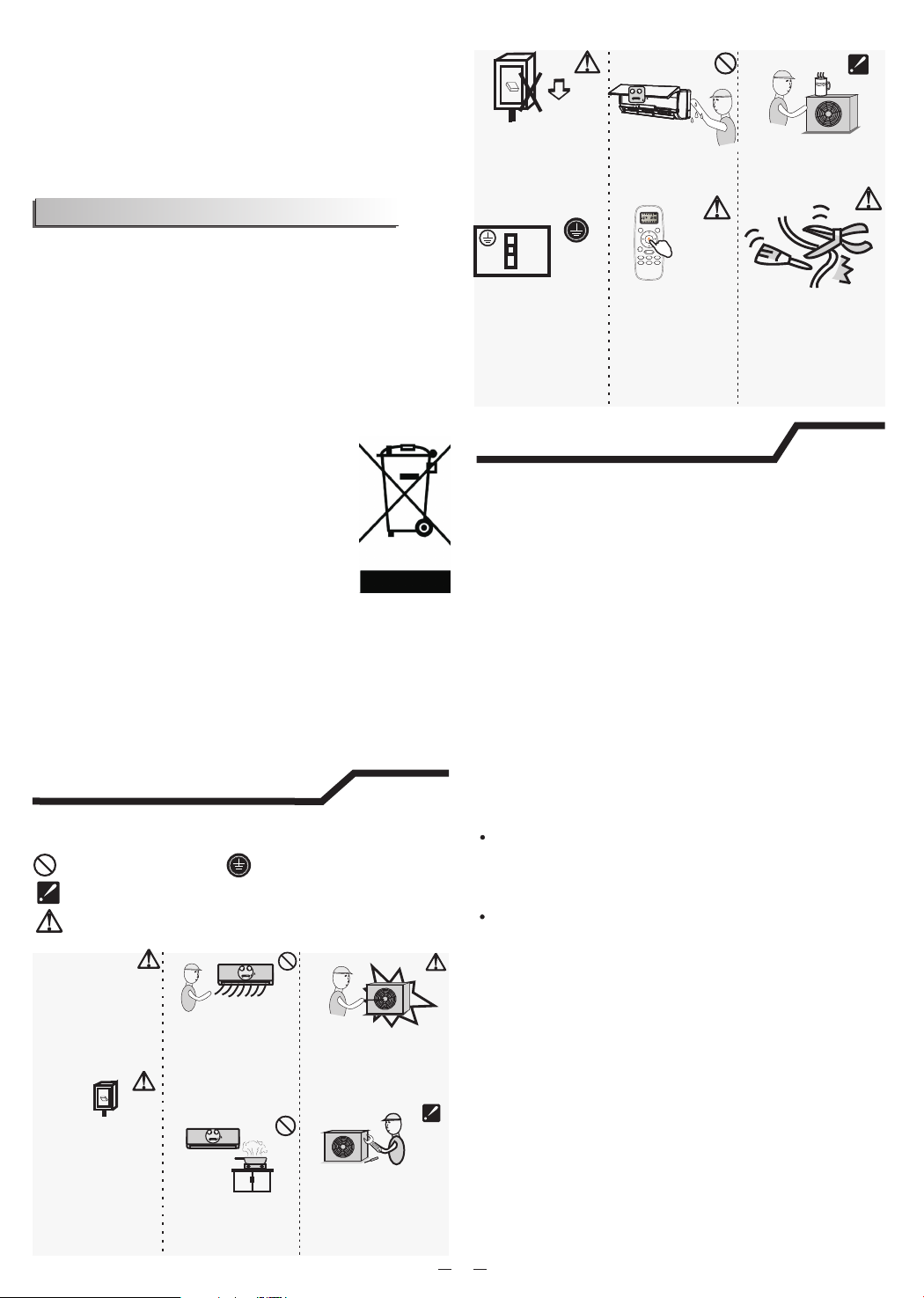
Warning: Incorrect handling could cause a
serious hazard, such as death, serious injury, etc.
Do not use the power
supply circuit breaker
or pull off the plug to
turn it off during
operation. This may
cause a fire due to
spark, etc.
OFF
ON
It is the user's
responsibility to
make the appliance
be grounded
according to local
codes or ordinances
by a licenced
technician.
Do not touch the
operation buttons
when your hands
are wet.
Turn off the
applianceby remote
control firstly before
cutting off power
supply if malfunction
occurs.
ON
OFF
MODE
SMART
QUIET DIMMER
ECONOMY
FEEL
FAN SPEED
CLOCK
TIMER ON
TIMER OFF
SLEEP
TEMP.
TEMP.
SUPER
Use correct power
supply inaccordance
with the rating plate
requirement.
Otherwise, serious
faults or hazard may
occur or a fire maybe
break out.
Keep the power
supply circuit
breaker or plug from
dirt. Connect the
power supply cord to
it firmly and correctly,
lest an electric shock
or a fire break out
due to insufficient
contact.
OFF
ON
It is harmful to your
health if the cool air
reaches you for a long
time. It is advisable to
let the air flow be
deflected to all the
room.
Prevent the air flow
from reachingthe gas
burners and stove.
Never insert a stick or
similar obstacle to the
unit. Since the fan
rotates at high speed,
this may cause an injury.
Do not repair the
appliance by yourself.
If this is done
incorrectly, it may cause
an electric shock, etc.
Do not put any objects
on the outdoor unit.
Do not knit, pull or
press the power supply
cord, lest the power
supply cord be broken.
An electric shock or fire
is probably caused by
a broken power supply
cord.
2
Safety precautions
1.Transport of equipment containing
flammable refrigerants
Compliance with the transport regulations
2.Marking of equipment using signs
Compliance with local regulations
3.Disposal of equipment using flammable
refrigerants
Compliance with national regulations
4.Storage of equipment/appliances
The storage of equipment should be in
accordance with the manufacturer's
instructions.
5.Storage of packed (unsold) equipment
Storage package protection should be
constructed such that mechanical damage to
the equipment inside the package will not
cause a leak of the refrigerant charge.
The maximum number of pieces of equipment
permitted to be stored together will be
determined by local regulations.
6.Information on servicing
6-1 Checks to the area
Prior to beginning work on systems containing
flammable refrigerants, safety checks are
necessary to ensure that the risk of ignition is
minimised. For repair to the refrigerating
system, the following precautions shall be
complied with prior to conducting work on the
system.
6-2 Work procedure
Work shall be undertaken under a controlled
procedure so as to minimise the risk of
flammable gas or vapour being present while
the work is being performed.
Precautions for using R32 refrigerant
The basic installation work procedures are the
same as the conventional refrigerant(R22 or
R410A). However, pay attention to the following
points:

6-3 General work area
All maintenance staff and others working in the
local area shall be instructed
on the nature of work being carried out. Work
in confined spaces shall be avoided.
The area around the workspace shall be
sectioned off. Ensure that the conditions
within the area have been made safe by
control of flammable material.
6-4 Checking for presence of refrigerant
The area shall be checked with an appropriate
refrigerant detector prior to and during work,
to ensure the technician is aware of
potentially flammable atmospheres.
Ensure that the leak detection equipment
being used is suitable for use with flammable
refrigerants, i.e. non-sparking, adequately
sealed or intrinsically safe.
6-5 Presence of fire extinguisher
If any hot work is to be conducted on the
refrigeration equipment or any associated
parts, appropriate fire extinguishing equipment
shall be available to hand.
Have a dry powder or CO2 fire extinguisher
adjacent to the charging area.
6-6 No ignition sources
No person carrying out work in relation to a
refrigeration system which
involves exposing any pipe work that contains
or has contained flammable refrigerant shall
use any sources of ignition in such a manner
that it may lead to the risk of fire or explosion
All possible ignition sources, including
cigarette smoking, should be kept sufficiently
far away from the site of installation, repairing,
removing and disposal, during which
flammable refrigerant can possibly be released
to the surrounding space.
Prior to work taking place, the area around the
equipment is to be surveyed to
make sure that there are no flammable hazards
or ignition risks. “No Smoking” signs shall be
displayed.
6-7 Ventilated area
Ensure that the area is in the open or that it is
adequately ventilated before breaking into the
system or conducting any hot work.
A degree of ventilation shall continue during
the period that the work is carried out.
The ventilation should safely disperse any
released refrigerant and preferably expel it
externally into the atmosphere
.
6-8 Checks to the refrigeration equipment
Where electrical components are being
changed, they shall be fit for the purpose and
to the correct specification.
At all times the manufacturer's maintenance
and service guidelines shall be followed. If in
doubt consult the manufacturer's technical
department for assistance
The following checks shall be applied to
installations using flammable refrigerants:
–The charge size is in accordance with the
room size within which the refrigerant
containing parts are installed;
–The ventilation machinery and outlets are
operating adequately and are not obstructed;
–If an indirect refrigerating circuit is being
used, the secondary circuit shall be checked
for the presence of refrigerant;
–Marking to the equipment continues to be
visible and legible. Markings and signs that
are illegible shall be corrected;
–Refrigeration pipe or components are
installed in a position where they are unlikely
to be exposed to any substance which may
corrode refrigerant containing components,
unless the components are constructed of
materials which are inherently resistant to
being corroded or are suitably protected
against being so corroded.
6-9 Checks to electrical devices
Repair and maintenance to electrical
components shall include initial safety checks
and component inspection procedures.
If a fault exists that could compromise safety,
then no electrical supply shall be connected to
the circuit until it is satisfactorily dealt with.
If the fault cannot be corrected immediately
but it is necessary to continue operation, an
adequate temporary solution shall be used.
This shall be reported to the owner of the
equipment so all parties are advised.
Initial safety checks shall include:
–That capacitors are discharged: this shall be
done in a safe manner to avoid possibility of
sparking;
–That there no live electrical components and
wiring are exposed while charging,
recovering or purging the system;
–That there is continuity of earth bonding
7. Repairs to sealed components
During repairs to sealed components, all
electrical supplies shall be disconnected from
the equipment being worked upon prior to any
removal of sealed covers, etc.
If it is absolutely necessary to have an
electrical supply to equipment during
servicing, then a permanently operating form
of leak detection shall be located at the most
critical point to warn of a potentially hazardous
situation.
Particular attention shall be paid to the
following to ensure that by working on
electrical components, the casing is not
altered in such a way that the level of
protection is affected.
3

This shall include damage to cables,
excessive number of connections, terminals
not made to original specification, damage to
seals, incorrect fitting of glands, etc.
Ensure that apparatus is mounted securely.
Ensure that seals or sealing materials have not
degraded such that they no longer serve the
purpose of preventing the ingress of flammable
atmospheres.
Replacement parts shall be in accordance with
the manufacturer's specifications.
NOTE:
The use of silicon sealant may inhibit the
effectiveness of some types of leak detection
equipment. Intrinsically safe components do
not have to be isolated prior to working on them.
8.Repair to intrinsically safe components
Do not apply any permanent inductive or
capacitance loads to the circuit without
ensuring that this will not exceed the
permissible voltage and current permitted for
the equipment in use.
Intrinsically safe components are the only
types that can be worked on while live in the
presence of a flammable atmosphere. The test
apparatus shall be at the correct rating.
Replace components only with parts specified
by the manufacturer. Other parts may result in
the ignition of refrigerant in the atmosphere
from a leak.
9.Cabling
Check that cabling will not be subject to wear,
corrosion, excessive pressure, vibration,
sharp edges or any other adverse
environmental effects.
The check shall also take into account the
effects of aging or continual vibration from
sources such as compressors or fans
10.Detection of flammable refrigerants
Under no circumstances shall potential
sources of ignition be used in the searching for
or detection of refrigerant leaks.
A halide torch (or any other detector using a
naked flame) shall not be used
11.Leak detection methods
The following leak detection methods are
deemed acceptable for systems containing
flammable refrigerants:
–Electronic leak detectors shall be used to
detect flammable refrigerants, but the
sensitivity may not be adequate, or may need
re-calibration. (Detection equipment shall be
calibrated in a refrigerant-free area.)
–Ensure that the detector is not a potential
source of ignition and is suitable for the
refrigerant used.
–Leak detection equipment shall be set at a
percentage of the LFL of the refrigerant and
shall be calibrated to the refrigerant employed
and the appropriate percentage of gas (25 %
maximum) is confirmed.
–Leak detection fluids are suitable for use with
most refrigerants but the use of detergents
containing chlorine shall be avoided as the
chlorine may react with the refrigerant and
corrode the copper pipe-work.
–If a leak is suspected, all naked flames shall
be removed/ extinguished.
–If a leakage of refrigerant is found which
requires brazing, all of the refrigerant shall be
recovered from the system, or isolated (by
means of shut off valves) in a part of the
system remote from the leak.
–Oxygen free nitrogen (OFN) shall then be
purged through the system both before and
during the brazing process.
12.Removal and evacuation
When breaking into the refrigerant circuit to
make repairs – or for any other purpose –
conventional procedures shall be used.
However, it is important that best practice is
followed since flammability is a consideration.
The following procedure shall be adhered to:
–Remove refrigerant;
–Purge the circuit with inert gas;
–Evacuate;
–Purge again with inert gas;
–Open the circuit by cutting or brazing.
The refrigerant charge shall be recovered into
the correct recovery cylinders.
The system shall be “flushed” with OFN to
render the unit safe.
This process may need to be repeated several
times.
Compressed air or oxygen shall not be used
for this task.
Flushing shall be achieved by breaking the
vacuum in the system with OFN and continuing
to fill until the working pressure is achieved,
then venting to atmosphere, and finally pulling
down to a vacuum.
This process shall be repeated until no
refrigerant is within the system. When the final
OFN charge is used, the system shall be
vented down to atmospheric pressure to
enable work to take place.
This operation is absolutely vital if brazing
operations on the pipe-work are to take place.
Ensure that the outlet for the vacuum pump is
not close to any ignition sources and there is
ventilation available.
13.Charging procedures
In addition to conventional charging
procedures, the following requirements shall
be followed:
–Ensure that contamination of different
refrigerants does not occur when using
charging equipment.
–Hoses or lines shall be as short as possible to
minimise the amount of refrigerant contained
in them.
4

–Cylinders shall be kept upright.
–Ensure that the refrigeration system is earthed
prior to charging the system with refrigerant.
–Label the system when charging is complete
(if not already).
–Extreme care shall be taken not to overfill the
refrigeration system.
Prior to recharging the system it shall be
pressure tested with OFN.
The system shall be leak tested on completion
of charging but prior to commissioning.
A follow up leak test shall be carried out prior
to leaving the site.
14.Decommissioning
Before carrying out this procedure, it is
essential that the technician is completely
familiar with the equipment and all its detail.
It is recommended good practice that all
refrigerants are recovered safely.
Prior to the task being carried out, an oil and
refrigerant sample shall be taken in case
analysis is required prior to re-use of
reclaimed refrigerant. It is essential that
electrical power is available before the task is
commenced.
a) Become familiar with the equipment and its
operation.
b) Isolate system electrically.
c) Before attempting the procedure ensure
that:
–Mechanical handling equipment is available,
if required, for handling refrigerant cylinders;
–All personal protective equipment is available
and being used correctly;
–The recovery process is supervised at all
times by a competent person;
–Recovery equipment and cylinders conform to
the appropriate standards.
d) Pump down refrigerant system, if possible.
e) If a vacuum is not possible, make a manifold
so that refrigerant can be
removed from various parts of the system.
f) Make sure that cylinder is situated on the
scales before recovery takes
place.
g) Start the recovery machine and operate in
accordance with manufacturer's instructions.
h) Do not overfill cylinders. (No more than
80 % volume liquid charge).
I ) Do not exceed the maximum working
pressure of the cylinder, even temporarily.
j ) When the cylinders have been filled
correctly and the process completed, make
sure that the cylinders and the equipment
are removed from site promptly and all
isolation valves on the equipment are
closed off.
k) Recovered refrigerant shall not be charged
into another refrigeration system unless it
has been cleaned and checked.
15.Labelling
Equipment shall be labelled stating that it has
been de-commissioned and emptied of
refrigerant.
The label shall be dated and signed.
Ensure that there are labels on the equipment
stating the equipment contain flammable
refrigerant.
16.Recovery
When removing refrigerant from a system,
either for servicing or decommissioning, it is
recommended good practice that all
refrigerants are removed safely.
When transferring refrigerant into cylinders,
ensure that only appropriate refrigerant
recovery cylinders are employed.
Ensure that the correct number of cylinders
for holding the total system charge is available
All cylinders to be used are designated for the
recovered refrigerant and labelled for that
refrigerant (i.e. special cylinders for the
recovery of refrigerant).
Cylinders shall be complete with pressure
relief valve and associated shut-off valves in
good working order.
Empty recovery cylinders are evacuated and,
if possible, cooled before recovery occurs.
The recovery equipment shall be in good
working order with a set of instructions
concerning the equipment that is at hand and
shall be suitable for the recovery of
flammable refrigerants.
In addition, a set of calibrated weighing scales
shall be available and in good working order.
Hoses shall be complete with leak-free
disconnect couplings and in good condition.
Before using the recovery machine, check
that it is in satisfactory working order, has
been properly maintained and that any
associated electrical components are sealed
to prevent ignition in the event of a refrigerant
release.
Consult manufacturer if in doubt.
The recovered refrigerant shall be returned to
the refrigerant supplier in the correct recovery
cylinder, and the relevant Waste Transfer
Note arranged.
Do not mix refrigerants in recovery units and
especially not in cylinders.
If compressors or compressor oils are to be
removed, ensure that they have been
evacuated to an acceptable level to make
certain that flammable refrigerant does not
remain within the lubricant.
The evacuation process shall be carried out
prior to returning the compressor to the
suppliers.
5

Only electric heating to the compressor body
shall be employed to accelerate this process.
When oil is drained from a system, it shall be
carried out safely.
When moving or relocating the air conditioner,
consult experienced service technicians for
disconnection and reinstallation of the unit
Do not place any other electrical products or
household belongings under indoor unit or
outdoor unit. Condensation dripping from the
unit might get them wet, and may cause
damage or malfunction of your property.
Do not use means to accelerate the defrosting
process or to clean, other than those
recommended by the manufacturer.
The appliance shall be stored in a room
without continuously operating ignition
sources(for example, open flames, an
operating gas appliance or an operating
electric heater).
Do not pierce or burn.
Be aware that refrigerants may not contain an
odor.
To keep ventilation openings clear of
obstruction.
The appliance shall be stored in a
well-ventilated area where the room size
corresponds to the room area as specified for
operation.
The appliance shall be stored in a room
without continuously operating open
flames (for example an operating gas
appliance) and ignition sources (for example
an operating electric heater).
Any person who is involved with working on or
breaking into a refrigerant circuit should hold
a current valid certificate from an industry-
accredited assessment authority, which
authorises their competence to handle
refrigerants safely in accordance with an
industry recognised assessment specification.
Servicing shall only be performed as
recommended by the equipment manufacturer.
Maintenance and repair requiring the
assistance of other skilled personnel shall be
carried out under the supervision of the
person competent in the use of flammable
refrigerants.
Do not use means to accelerate the defrosting
process or to clean, other than those
recommended by the manufacturer.
Appliance shall be installed, operated and
stored in a room with a floor arealarger than
2
10 m .
The installation of pipe-work shall be kept to a
2
a room with a floor area largerthan 10 m .
The pipe-work shall be complianced with
national gas regulations.
The maximum refrigerant charge amount is
2.5 kg.The specific refrigerant charge is
based on the nameplate of the outdoor unit
Mechanical connectors used indoors shall
comply with ISO 14903. When mechanical
connectors are reused indoors, sealing parts
shall be renewed. When flared joints are
reused indoors, the flare part shall be
re-fabricated.
The installation of pipe-work shall be kept to
a minimum.
Mechanical connections shall be accessible
for maintenance purposes.
Installation must be performed in accordance with
the national wiring standards by authorized personnel only.
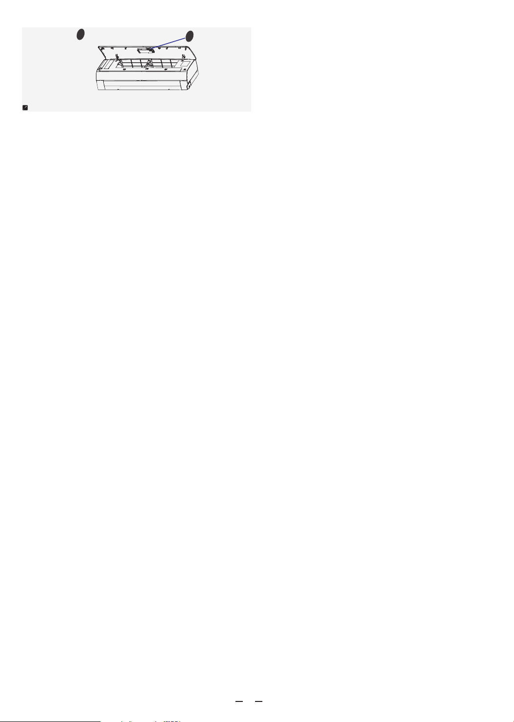
Above figure is only a simple presentation
of the unit, it may not match the external
appearance of the unit you purchased.
Explanation of symbols displayed on the indoor
unit or outdoor unit.
6
This symbol shows that this appliance
uses a flammable refrigerant.
If the refrigerant is leaked and exposed
to an external ignition source, there is a
risk of fire
This symbol shows that this appliance
usesa flammable refrigerant.
If the refrigerant is leaked and exposed
to an external ignition source, there is a
risk of fire
[symbol ISO
7010-W021
(2011-05)]
A2L symbol
[symbol ISO
7000-0790
(2004-01)]
[symbol ISO
7000-1659
(2004-01)]
[symbol ISO
1641-0790
(2004-01)]
This symbol shows that the operation
manual should be read carefully.
This symbol shows that a service
personnel should be handling this
equipment with reference to the
installation manual.
This symbol shows that information is
available such as the operating manual
or installation manual.
WARNING
WARNING
CAUTION
CAUTION
CAUTION
Caution, risk of fire
Waring;low burning
velocity material
Select the installation locations
Location for Installing Indoor Unit
1. Where there is no obstacle near
the air outlet andair can be easily
blown to every corner.
2. Where piping and wall hole can
be easily arranged.
3. Keep the required space from
the unit to the ceiling and wall
according to the installation
diagram on previous page.
4. Where the air filter can be easily
removed.
5. Keep the unit and remote controller 1m or more
apart from television, radio etc.
6. Keep as far as possible from fluorescent lamps.
7. Do not put anything near the air inlet to obstruct it
from air absorption.
8. Install on a wall that is strong enough to bear the
weight of the unit.
9. Install in a place that will not increase operation
noise and vibration.
10. Keep away from direct sunlight and heating
sources. Do not place flammable materials or
combustion apparatuses on top of the unit.
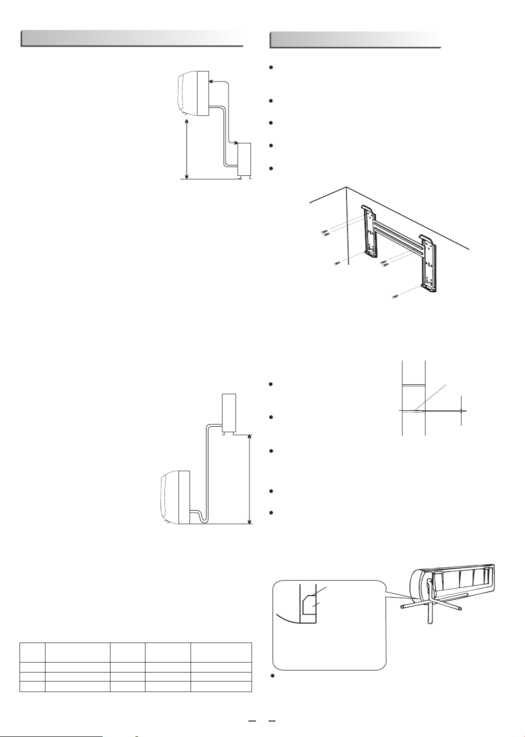
Pipe length
is 15 meters
Max.
Height should
be less than 5m
Indoor unit
Outdoor
unit
Location for Installing Outdoor Unit
1. Where it is convenient to install and well ventilated.
2. Avoid installing it where flammable gas
could leak.
3. Keep the required distance
apart from the wall.
The pipe length between indoor and
outdoor unit should be not more than
5 meters in factory default status, but it
can go up to maximum 15 meters with
additional refrigerant charge.
6. Keep the outdoor unit away
from greasy dirt, vulcanization
gas exit.
7. Avoid installing it by the
roadside where there is a risk
of muddy water.
8. A fixed base where it is not subject to increased
operation noise.
9. Where there is not any blockage of the air outlet.
10. Avoid installing under direct sunlight, in an aisle
or sideway, or near heat sources and ventilation fans.
Keep away from flammable materials, thick oil fog,
and wet or uneven places.
If the height or pipe length is out of the scope of the
table, please consult the dealer.
Outdoor unit
Indoor unit
Pipe length is
15 meters Max.
be less than 5m
Height should
Model
5K~18K 515
Max. allowed pipe
length without additional
refrigerant (m)
Limit of
length (m)
pipe
21K 25K~
28K~36K
515
515
520
Limit of Elevation
Difference H (m)
Required amount of
additional refrigerant
(g/m)
530
540
Indoor unit installation
1. Installing the Mounting Plate
Decide an installing location for the mounting plate
according to the indoor unit location and pipe
direction.
Keep the mounting plate horizontally with a
horizontal ruler or level.
Drill holes of 32mm in depth on the wall for fixing
the plate.
Insert the plastic plugs to the hole, fix the mounting
plate with tapping screws.
Inspect if the mounting plate is well fixed. Then
drill a hole for pipe.
Mounting plate
Tapping screw
Note: The shape of your mounting plate may be different
from the one above, but the installation method is similar.
Note: As the above figure shown, the six holes matched with
tapping screw on the mounting plate must be used to fix the
mounting plate, the others are prepared.
2. Drill a Hole for Pipe
Decide the position of hole
for pipe according to the
location of mounting plate.
Drill a hole on the wall
about 50mm. The hole
should tilt a littledownward toward outside.
Install a sleeve through the wall hole to keep the wall
tidy and clean.
Indoor
Outdoor
Wall hole sleeve
( hard polythene tube
prepared by user)
5mm
(tilt downward)
3. Indoor Unit Pipe Installation
Put the pipes (liquid and gas pipe) and cables
through the wall hole from outside or put them
through from inside after indoor pipe and cables
connection complete so as to connect to outdoor
unit.
Decide whether saw the unloading piece off in
accordance with the pipe direction.(as shown
After connecting pipe as required, install the drain
hose. Then connect the power cords. After
connecting, wrap the pipes, cords and drain hose
together with thermal insulation materials.
7
Note: When installing the pipe
at the directions 1,2 or 4, saw
the corresponding unloading
piece off the indoor unit base.
Pipe direction
1
2
Trough
knock-down panel
Cut off the Knock-down panel
along the trough using needle
nose pliers or other suitable
tool.
below)
3
4

Pipe Joints Thermal Insulation:
Wrap the pipes joints with thermal insulation
materials and then wrap with a vinyl tape.
Thermal insulation
wrapped with vinyl type
Pipes Thermal Insulation:
a. Place the drain hose under the pipes.
b. Insulation material uses polythene
foam over 6mm in thickness.
Note: Drain hose is prepared by user.
Drain pipe should point downward
for easy drain flow. Do not arrange
the drain pipe twisted, sticking out
or wave around, do not immerse
the end of it in water.
If an extension drain hose is connected to the drain
pipe, make sure to thermal insulated when passing
along the indoor unit.
When the pipes is directed to the right, pipes, power
Cord and drain pipe should be thermal insulated and
fixed onto the back of the unit with a pipe fixer.
Small
pipe
Large pipe
Thermal insulation tube
Power cord
Drain hose
(prepared by user)
A. Insert the pipe fixer to the slot. B. Press to hook the pipe fixer
onto the base.
Base Base
Base
Pipe fixer Pipe fixer
Hook here
Insert here
drain
hose
drain
hose
large
pipe
large
pipe
small
pipe
small
pipe
(just a schematic)
Piping Connection:
If you don't hear the exhaust noise,
please contact with the merchant.
a.Before unscrewing the big and the
small sealing caps, press the small
sealing cap with the finger until the
exhaust noise stops, and then
loosen the finger.
b.Connect indoor unit pipes with
two wrenches. Pay special attention
to the allowed torque as shown
below to prevent the pipes,
connectorsand flare nuts from being
deformed and damaged.
c. Pre-tighten them with fingers at
first, then use the wrenches.
Pipe size
Model
Liquid Side ( 1/4 inch) φ6mm or
5k~12K,13k~18K,21 K~24
12K , 13K~18K
#
18K , 21K~36K
#
#
18K , 21K~36K
5K~13K
15~20N·m
17mm 0.5mm
0.6mm
0.6mm
0.6mm
0.6mm
22mm
24mm
22mm
27mm
30~35N·m
30~35N·m
50~55N·m
60~65N·m
Liquid Side ( 3/8 inch)φ9.53mm or
Gas Side ( inch)φ12mm or 1/2
Gas Side ( 3/8 inch)φ9.53mm or
Gas Side ( 5/8 inch)φ16mm or
Torque Nut width Min.thickness
1.0mm
36K# 32mm
Gas Side ( 3/4 inch)φ19mm or 70~75N·m
Note: Piping connection should be conducted on outdoor
side !
For Inverter appliance
For ON-OFF appliance
# # # #
Note: The unit of 12K ,18K ,24K ,36K is bigger than the unit of
12K,18K,24K,36K.
Pipe size
Model
Liquid Side ( 1/4 inch) φ6mm or
5 12K,13 18K,21 24K~ ~ ~
12 ,14,15,18K
#
K
#
18K ,22,24K ,28,30,36K
#
18K ,22,24,28,30,36K
#
36K#
5~10K,12K
15~20N·m
17mm 0.5mm
0.6mm
0.6mm
0.6mm
0.6mm
22mm
24mm
22mm
27mm
30~35N·m
30~35N·m
50~55N·m
60~65N·m
Liquid Side ( 3/8 inch)φ9.53mm or
Gas Side ( inch)φ12mm or 1/2
Gas Side ( 3/8 inch)φ9.53mm or
Gas Side ( 5/8 inch)φ16mm or
Torque Nut width Min.thickness
1.0mm
32mm
70~75N·m
Gas Side ( 3/4 inch)φ19mm or
4. Connecting of the Cable
Outdoor Unit
Indoor Unit
1) Remove the access door from the unit by
loosening the screw. Connect the wires to the
terminals on the control board individually as
follows.
Connect the power cord to the indoor unit by
connecting the wires to the terminals on the control
board individuallyin accordance with the outdoor
unit connection.
2) Secure the power cord onto the control
with cable clamp.
board
.
3) Reinstall the access door to the original position
with the screw.
4) Use a recognized circuit breaker for 24K model
between the power source and the unit. A
disconnecting device to adequately disconnect all
supply lines must be fitted.
Note: For some models, it is necessary to remove the
cabinet to connect to the indoor unit terminal.
Access door
Terminal(inside)
Outdoor unit
The figures in this manual are based on the external
view of a standard model. Consequently, the shape
may differ from that of the air conditioner you have
selected.
Chassis
Cabinet
Front panel
Terminal (inside)
Indoor unit
Caution:
1. Never fail to have an individual power circuit specifically
for the air conditioner. As for the method of wiring, refer to
the circuit diagram posted on the inside of the access door.
2. Comfirm that the cable thickness is as specified in the
power source specification.
3. Check the wires and make sure that they are all tightly
fastened after cable connection.
4. Be sure to install an earth leakage circuit breaker in wet or
moist areas.
8
# # #
Note: The unit of 12K ,18K and 36K is bigger than the unit of 12K,
18K and 36K.
Attention:
The plug must be accessible even after the installation of the
appliance in case there is a need to disconnect it. If not
possible, connect appliance to a double-pole switching device
with contact separation of at least 3 mm placed in an
accessible position even after installation.
Cable Specifications for Inverter appliance
NOTE:
NOTE:
1.K* means the this model comes from indoor unit.
2.K** indicates indoor power supply unit model with power line and
plug.
3.For 14K*~18K* models under Tropical(T3) Climate condition, the
normal cross-sectionl area of Power cord and Power connecting
2
cord is 2.5mm ×4
power supply of
.
Capacity
(Btu/h)
5K~13K
H07RN-F
IS:9968
H05VV-F
IS:694
IS:694
IS:694
5K*~ K*13
Power connecting cord
Power cord
Type Type
Normal cross
- sectional area
Normal cross
- sectional area
0.75~1.5 2
mm X4
0.75~1.5 2
mm X4
0.75~1.5 X3
2
mm
2
0.75~1.5mm X3
H07RN-F
H07RN-F
H05VV-F
H05VV-F
2
2.5mm X3
2
2.5mm X3
2
1.5mm X3
2
2.5mm X4
2
2.5mm X4
2
1.5mm X4
2
1.0mm X4
H07RN-F
2
2.5mm X3
H07RN-F
2
2.5mm X3
H07RN-F
2
2.5mm X5
H07RN-F
H07RN-F
IS:9968
IS:9968
2
1.5/2.5mm X3
2
1.5/2.5mm X3
H05VV-F 2
1.5/2.5mm X4
2
1.5/2.5mm X4
21K*~30K*
21K**~24K**
21K~36K
H07RN-F H05RN-F 2
0.75mm X4
0.75~1.5 X3
2
mm
14K*~ K*18
H07RN-F 2
1.5mm X3 H07RN-F 2
1.5mm X5
H07RN-F H07RN-F 0.75~1.5 2
mm X5
0.75~1.5 X3
2
mm
14K~18K
H07RN-F 2
1.5mm X3 H05RN-F 2
0.75mm X4
2
0.75mm X4
H05RN-F
2
2.5mm X3
H07RN-F
Cable Specifications for ON-OFF appliance
2
2
The cord may be different from the list above. It may be used as
the next list. And it can be larger.0-6A, use 0.75mm or 18AWG.
0-10A, use 1mm or 16AWG. 0-16A, use 1.5mm or 14AWG 0-20A,
use 2.5mm or 14AWG. 0-25A, use 2.5mm or 12AWG. 0-32A,
use 4mm
2
2 2
22
2
Capacity
(Btu/h)
To indoor
H07RN-F
Power connecting cord
Power cord
Type Type Type
Normal cross
- sectional area
Main
power
supply
Normal cross
- sectional area
Normal cross
- sectional area
Power connecting cord1
2
2.5mm X3
To indoor
To outdoor
2
1.5~2.5mm X3
5K~13K
H05VV-F
2
0.75~1.5mm X3
H05VV-F
H05RN-F
H05RN-F
H05RN-F
2
1.5~2.5mm X3
2
0.75mm X2
(Heat-pump)
2
0.75mm X2
(Heat-pump)
2
0.75mm X3
(Heat-pump)
H07RN-F
H05RN-F
H07RN-F
2
0.75~1.0mm X3
2
1.5mm X3
2
1.0mm X3
2
1.0mm X4Cooling only
To indoor
18K~30K
2
1.5~2.5mm X3
H05VV-F 2
1.5~2.5mm X4
H07RN-F
H07RN-F 2.5~ X3
2
4.0mm
To outdoor
24K~36K
H05RN-F
H07RN-F
14K~24K
H05RN-F
2
0.75mm X2
(Heat-pump&Optional)
18K~30K
H07RN-F 1.5 X5
2
mm
To outdoor
H05RN-F 2
0.75mm X4
24K~36K
H05RN-F
2
0.75mm X2
(Heat-pump)
H05RN-F
H07RN-F 2
1.0mm X4
2
0.75mm X4
H05RN-F
2
0.75mm X2
(Heat-pump&Optional)
Wiring diagram
Warning:
Before obtaining access to terminals, all supply
circuits must be disconnected.
Make sure that the color of the wires in the outdoor
unit and terminal No. are the same as those of the
indoor unit, the details please refer to the wiring
diagram which is near the terminal inside the unit.
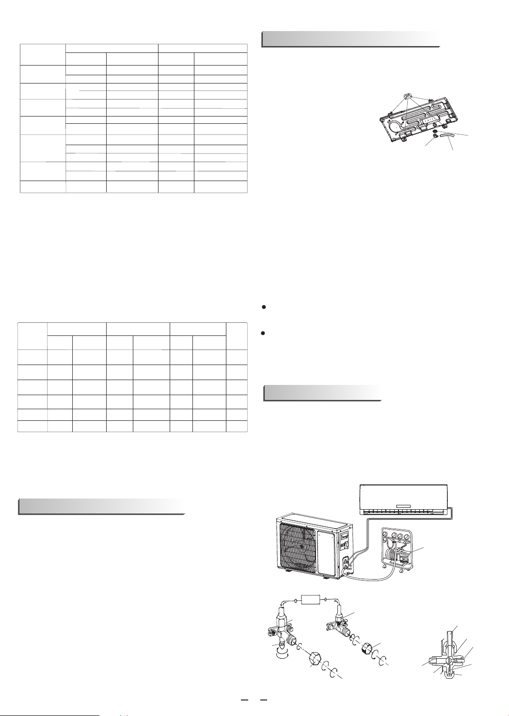
Outdoor unit installation
1. Install Drain Port and Drain Hose (for heat-pump
model only)
Drain hose
(prepared by user)
Washer
Drain port
Rubber pad (optional)
Place under the leg pedestal
The condensate drains
from the outdoor unit when
the unit operates in heating
mode. In order not to
disturb your neighbor and
protect the environment, install
a drain port and a drain hose to direct
the condensate water. Just install the drain port and
rubber washer to the chassis of the outdoor unit,
then connect a drain hose to the port as the right
figure demonstrates.
2. Install and Fix Outdoor Unit
Fix with bolts and nuts tightly on a flat and strong
floor. If installed on the wall or roof, make sure to fix
the supporter well to prevent it from shaking due to
serious vibration or strong wind.
3. Outdoor Unit Piping Connection
Remove the valve caps from the 2-way and 3-way
valve.
Connect the pipes to the 2-way and 3-way valves
separately according to the required torque.
4. Outdoor Unit Cable Connection (see previous
page)
Air purging
The air which contains moisture remaining in the
refrigeration cycle may cause a malfunction on the
compressor. After connecting the indoor and outdoor
units, release air and moisture from the refrigerant
cycle using a vacuum pump, as shown below.
Note: To protect the environment, be sure not to discharge
the refrigerant to the air directly.
Refrigerant flow direction 2-way valve
(6) Open 1/4 turn
valve cap
(1) Turn
(8) Tighten
(2) Turn
3-way valve
(8) Tighten
(1) Turn
(7) Turn to fully open the
valve
(7) Turn to fully open the valve
(8) Tighten
3-way valve diagram
connect to indoor unit
open position
spindle
service port cap
Service
port
Connect to outdoor unit
Valve core
needle
indoor unit
Valve cap
Vacuum pump
9
shock!
Electric
Dangerous!
(1) Unscrew and remove caps from 2 and 3-way
valves.
(2) Unscrew and remove cap from service valve.
(3) Connect vacuum pump flexible hose to the
service valve.
(4) Start vacuum pump for 10-15 minutes until
reaching a vacuum of 100Pa absolutes.
(5) With vacuum pump still running close the low
pressure knob on vacuum pump manifold. Then stop
the vacuum pump.
(6) Open 2-way valve ,1/4 turn, then close it after 10
seconds. Check tightness of all joints using liquid
soap or an electronic leak detector
(7) Turn 2 and 3-way valves stem to fully open the
valves. Disconnect the flexible vacuum pump hose.
(8) Replace and tighten all valve caps.
.
How to Purge Air Tubes:
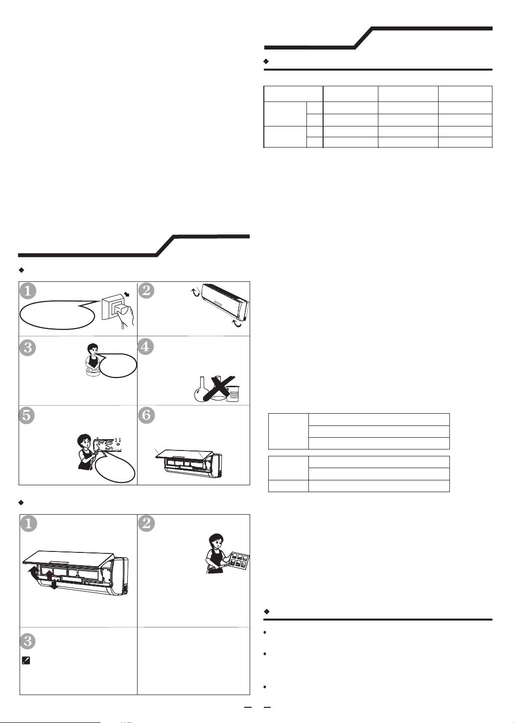
Maintenance
Front panel maintenance
Air filter maintenance
Close the front panel again
Wipe with a
soft and dry cloth.
Use soft moisture cloth to
clean if the front panel is
very dirty;
Never sprinkle water onto
the indoor unit
Clean the air filter every two weeks
if the air conditioner operates in an
extremely dusty environment.
Stop the appliance, c
the power supply and remove
the air filter.
ut off
1
2
1.Open the front panel.
2.Press the handle of the filter gently from
the front.
3.Grasp the handle and slide out the filter.
Turn off the appliance
first before disconnecting
from power supply.
Cut off the power supply
a
a
Grasp position "a"
and pull outward to
remove the front panel.
soft cloth to
clean it.
Use a dry and
Never use volatile
substance such as gasoline
or polishing powder to clean
the appliance.
Reinstall and shut the
front panel.
Reinstall and shut the front panel by
pressing position "b" downward.
bb
3
Clean and reinstall the
air filter.
If the dirt is conspicuous,
wash it with a solution of
detergent in lukewarm
water.After cleaning,
dry well in shade.
It is necessary to clean the air filter
after using it for about 100 hours.
Protection
Operating temperature for Inverter appliance
Operating condition
Temperature Cooling operation Heating operation
Indoor
temperature
max 32℃27℃
min 21℃7℃
Outdoor
temperature
max *note 24℃
min *note
*note
-15℃
Drying operation
32℃
18℃
43℃
21℃
NOTE:
*Optimum performance will be achieved within these
operating temperature. If air conditioner is used outside of
the above conditions, the protective device may trip and
stop the appliance.
*Normally,the outdoor max temperature is 43 ,but some
models will be achieved 46℃,48℃,or 50℃For Tropical (T3)
Climate condition models, the outdoor max temperature is
55 ℃.
*For some models, can keep cooling at -15 ℃ outdoor
ambient via unique design. Normally, optimum cooling
performance will be achieved above 21 ℃. Please consult
the merchant to get more information.
*For some models, can keep heating at -15 ℃ outdoor
ambient , some models heat at -20 ℃outdoor ambient, even
heat at lower outdoor ambient
The temperature of some products is allowed beyond the
range. In specific situation, please consult the merchant.
When relative humidity is above 80%, if the air conditioner
runs in COOLING or DRY mode with door or window
opened for a long time, dew may drip down from the outlet.
℃
.
The protective device maybe trip and stop the
appliance in the cases listed below
*
The temperature of some products is allowed beyond
the range. In specific situation, please consult the
merchant.
If the air conditioner runs in COOLING or DRY mode
withdoor or window opened for a long time when
relative humidity is above 80%,dew may drip down
from the outlet.
Normally,the outdoor max temperature is 43 ,but
some models will be achieved 46℃,48℃or 50℃.For
Tropical (T3) Climate condition models, the outdoor
max temperature is 55 ℃.
℃
,
NOTE:
Operating temperature for ON-OFF appliance
HEATING
o
Outdoor air temperature is over 24 C
COOLING
DRY
o
Outdoor air temperature is below -7 C
o
Room temperature is over 27 C
o
Room temperature is below 21 C
o
Room temperature is below 18 C
Noise pollution
Install the air conditioner at a place that can bear
its weight in order to operate more quietly.
Install the outdoor unit at a place where the air
discharged and the operation noise would not
annoy your neighbors.
Do not place any obstacles in front of the air outlet
of the outdoor unit lest it increases the noise level.
10

Features of protector
1. The protective device will work at following cases.
Restarting the unit at once after operation stops or
changing mode during operation, you need to wait
for 3 minutes.
Connect to power supply and turn on the unit at
once, it may start 20 seconds later.
2. If all operation has stopped, press ON/OFF
button again to restart, Timer should be set again
if it has been canceled.
Features of HEATING mode
Preheat
At the beginning of the HEATING operation, the
airflow from the indoor unit is discharged 2-5 minutes
later.
In HEATING operation the appliance will defrost
(de-ice) automatically to raise efficiency.
This procedure usually lasts 2-10 minutes. During
defrosting, fans stop operation.
After defrosting completes, it returns to HEATING
mode automatically.
Note: Heating is NOT available for cooling only
air conditioner models.
Defrost
Troubleshooting
The following cases may not always be a
malfunction, please check it before asking for
service.
Trouble Analysis
Trouble Analysis
Does not run 1. If the protector trip or fuse is blown.
2. Please wait for 3 minutes and start
again, protector device may be
preventing unit to work.
3. If batteries in the remote controller
exhausted.
4. If the plug is not properly plugged.
No cooling or heating air 1. Is the air filter dirty
2. Are the intakes and outlets of the air
conditioner blocked?
3. Is the temperature set properly?
?
Ineffective control If strong interference(from excessive
static electricity discharge, power
supply voltage abnormality)presents,
operation will be abnormal. At this time,
disconnect from the power supply and
connect back 2-3 seconds later.
Does not operate
immediately
don't run
Changing mode during operation,
3 minutes will delay.
Peculiar odor This odor may come from another
source such as furniture, cigarette etc,
which issucked in the unit and blows
out with the air.
A sound of flowing water Caused by the flow of refrigerant in the
air conditioner, not a trouble.
Defrosting sound in heating mode.
Cracking sound is heard The sound may be generated by the
expansion or contraction of the front
panel due to change of temperature.
Spray mist from the outlet Mist appears when the room air
becomes very cold because of cool air
discharged from indoor unit during
COOLING or DRY operation mode.
The compressor indicator
(red) lights on constantly,
and indoor fan stops.
The unit is shifting from heating mode
to defrost.The indicator will lights off
within ten minutes andreturns to
heating mode.
The symbols may be different from these models, but the functions are similar.
Example:
81
2
34
Display introduction
NO
Display
Introduction
7
9
11
12
13
14
1
5
8
6
3
4
10
2
Temperature indicator
Display set temperature.
It shows FC after 200 hours of usage as
reminder to clean the filter.After filter cleaning
press the filter reset button located on the
indoor unit behind the front panel in order to
reset the display.(optional)
Running indicator
It lights up when the AC is running.
It flashes during defrosting.
Timer indicator
It lights up during set time.
Sleep indicator
It lights up in sleep mode
Compressor indicator
It lights up when the compressor is on
Mode indicator
Heating displays orange,others display white
Fan speed indicator
Smart WIFI indicator
It lights up during WIFI is on
NANOE indicator
It lights up in NANOE mode.
FAN ONLY mode indicator
It lights up in FAN ONLY mode
Airflow Follow You/Airflow Avoid You
indicator
Humidity indicator
It lights up in humidity mode.
Artificial Intelligence Smart Running
Indicator
It lights up in AI mode
Signal Receptor
AI
1 2 3 4 5 8
11
Emergency button
A
Pressing this button can let the AC run or stop.
A
The symbol may be different from your model, but the button is similar.
12

1
Table des matières
2
6
6
7
11
7
10
10
11
1
Mode d’emploi de la télécommande. Voir la rubrique « Mode d’emploi
de la télécommande »
8
9
9
9
Consignes de sécurité
Préparation pré-installation
Précautions de sécurité
Consignes d’installation
Schéma d’installation
Choisissezl’emplacement de votre appareil
Installation de l’unité intérieure
Raccordement du câble
Schéma de câblage
Installation de l’unité extérieure
Purge de l'air
Entretien
Protection
Dépannage
Présentation de l’affichage
Consignes de sécurité
Préparation pré-installation
1. Afin de garantir un fonctionnement normal de votre
appareil,veuillez lire attentivement ce manuel avant toute
installation et veuillez respecter les consignes qui y sont
livrées.
2.Ne laissez pas l’air pénétrer dans le système réfrigérant
ou d’évacuation lorsque vous déplacez le climatiseur.
3. Vérifiez bien la connexion au sol de votre appareil.
4. Vérifiez les câbles de raccordement ainsi que les
conduits et assurez-vous qu’ils sont tous bien fixes avant
de mettre le climatiseur en marche.
5. Le système est doté d’un bouton d’arrêt d’urgence.
6. Après l’installation, l’utilisateur doit faire fonctionner
l’appareil conformément aux consignes livrées dans le
manuel d’utilisation, stocker, entretenir et déplacer le
climatiseur comme cela est indiqué.
7. Fusible de l’unité intérieure T3.15A 250VAC or T5A
250VAC. Veuillez-vous reporter à l’information sur la carte
de circuit pour les paramètres corrects, qui doivent être
cohérents avec l’information sur la carte.
8. Pour les modèles 5K~13K, fusible de la partie extérieure
de l’appareil: T15A 250VAC or T20A 250VAC. Veuillez
vous référer à la sérigraphie sur la carte de circuit imprimé
pour les paramètres réels, qui doivent être cohérents avec
les paramètres sur la sérigraphie.
9. Pour les modèles 14K~18K, fusible de la partie
extérieure de l’appareil: T 20A 250VAC.
10. Pour les modèles 21K~36K, fusible de la partie
extérieure de l’appareil :T 30A 250VAC.
11. Les consignes d’installation livrées avec cet appareil
permettent de garantir un câblage correct, et pour éviter
les risques de fuites électriques (tension à respecter: 10
mA). Vérifiez bien qu’un dispositif de courant résiduel
(DCR) est installé (sur votre réseau et ne dépasse pas 30
mA).
12. Attention: risque d’électrocution pouvant entraîner des
blessures graves, voire la mort: Débranchez les sources
d’alimentation extérieures avant toute opération e
dépannage.
13. La longueur maximale du raccordement entre l’unité
intérieure et l’unité extérieure doit être inférieure à 5
mètres. Une longueur supérieure pourrait endommager le
fonctionnement du système.
14. Cet appareil n’est pas conçu pour être utilisé par des
personnes (y compris les enfants) ayant des capacités
physiques, sensorielles ou mentales réduites, ou ne
disposant pas d’une expérience et des connaissances
adéquates, à moins d’être supervisé ou instruit par une
personne responsable de leur sécurité. Les enfants doivent
être surveillés par un adulte qui doit s’assurer qu’ils ne
jouent pas avec l’appareil.
15. Cet appareil peut être utilisé par des enfants âgés de 8
ans et plus, ainsi que par des personnes dont les capacités
mentales, sensorielles et physiques sont réduites, si elles
ont appris à l’utiliser ou si elles sont placées sous la
surveillanced’une personne responsable. Les enfants ne
doivent pas jouer avec l’appareil. Le nettoyage et
l'entretien par l'utilisateur ne doivent pas être effectués par
des enfants sans surveillance.
16. Les piles de la télécommande doivent êtrerecyclées ou
mises au rebut selon les normes en vigueur. Mise au rebut
des piles usagées --- Merci de vous débarrasser de ces
piles dans la déchetterie la plus proche ou de faire appel
aux autorités compétentes.
17. Si l'appareil utilise un câblage fixe, il doit être équipé
de systèmes de déconnex du réseau d'alimentation, au
moyen d’un système de séparation de contact sur tous les
pôles, afin de permettre une coupure en cas de
problèmes de surtension de catégorie III.
18. Ces systèmes doivent être installés conformément aux
règlementations en vigueur.Si le cordon d'alimentation est
endommagé, il doit être remplacé par le fabricant, son
agent de service ou un technicien qualifié afin d'éviter tout
danger potentiel.
19. L'appareil doit être installé conformément aux
règlementations en matière de câblage.
20. L'entretien ne doit être effectué que selon les
recommandations du fabricant de l'équipement. La
maintenance et les réparations nécessitant l'assistance
d'un autre personnel qualifié doivent être effectuées sous
la supervision de la personne compétente pour l'utilisation
des réfrigérants inflammables.
21. L'appareil ne doit pas être installé dans une buanderie.
22. En ce qui concerne l’installation, veuillez-vous référer
au chapitre « Instructions d’installation ».
23. En ce qui concerne l’entretien, veuillez-vous référer au
chapitre « Entretien ».
24. Pour des modèles utilisant du réfrigérant R32,a
connexion l des tuyaux devrait être effectuée du côté
extérieur.
Remarque
1. Lorsque vous approvisionnez le système en liquide
frigorigène, vérifiez bien que ce dernier est complètement
liquide, surtout s'il s'agit d'un liquide catégorie R32.
Autrement, la composition chimique du liquide (R32) peut
varier et cela peut affecter la performance du climatiseur.
2. Selon le type de liquide frigorigène utilisé (R32, la valeur
GWP est égale à 675), la pression du tube est très élevé;
soyez donc attentif lorsque vous installez et réparez
l'appareil.
3. Si le cordon d'alimentation est endommagé, il doit être
remplacé par le fabricant, l'un de ses agents ou toute autre
personne qualifiée, afin d'écarter tout risque.
4. L'installation de cet appareil doit être prise en charge par
une personne qualifiée et expérimentée, conformément aux
consignes livrées dans cette notice.
5. La température à l'intérieur du circuit frigorigène sera
élevée; merci de maintenir le câble de raccordement à
l'écart du tube en cuivre.
Pré-réglages
Avant d'utiliser le climatiseur, vérifiez bien les pré-réglages
suivants.
1.Pré-réglage à distance
Dès que de nouvelles piles sont installées dans la
télécommande, cette dernière passe automatiquement en
mode « préchauffage de la pompe » par défaut. Dans le
cas où le climatiseur que vous avez acheté ne soit pas un
modèle réversible, une télécommande spéciale pour la
pompe à chaleur peut être utilisée.
11

2. Rétroéclairage de la télécommande (optionnel)
Maintenez n'importe quelle touche de la télécommande
enfoncée pour activer le rétroéclairage. Ce dernier se
désactive automatiquement après 10 secondes.
Remarque: Le rétroéclairage est une fonction
disponible en option.
3. Pré-réglage du redémarrage automatique
Le climatiseur est doté d'une fonction de redémarrage
automatique.
Préservation de l'environnement
Cet appareil est constitué de matériaux recyclables et
réutilisables. Son élimination doit se faire conformément aux
normes en vigueur. Avant de vous en débarrasser, pensez
à bien sectionner le cordon d'alimentation ainsi que les
conduites, de façon à ce qu'il ne puisse pas être réutilisé.
Pour plus d'informations à propos de recyclage et de
l'élimination de cet appareil, contactez la boutique auprès de
laquelle vous avez acheté cet appareil, ou les Autorités / le
Centre de Tri les plus proches.
ELIMINATION DE L'APPAREIL
Cet appareil est protégé par la Directive
Européenne 2012/19/CE relative à
l'élimination des déchets
électroniques (WEEE).
Cette directive indique que cet appareil ne
peut pas être éliminé avec les autres déchets
domestiques. Afin d'éviter tout risque pour
l'environnement et la santé humaine, recyclez
cet appareil de façon responsable et
écologique, afin de favoriser la réutilisation
des ressources matérielle. Pour éliminer votre appareil,
transférez-le vers un centre de tri ou contactez la boutique
auprès de laquelle vous l'avez a cheté. Ces derniers
pourront prendre en charge son élimination.
Précautions de sécurité
Les symboles contenus dans le manuel
d’utilisation sont expliqués à la suite.
A éviter absolument.
Situation à risques.
Connexion au sol obligatoire.
Attention: une mauvaise manipulation peut entraîner
une blessure grave, voire la mort.
N’utilisez pas le disjoncteur
et ne débranchez pas la
prise pendant que le
climatiseur est en marche.
Cela pourrait entraîner un
risque d’incendie.
OFF
ON
Il est de la responsabilité
de l’utilisateur de veiller à
ce que l’appareil soit relié
au sol conformément aux
règlementations électriques
en vigueur.
Ne touchez pas les
boutons d’utilisation
avec les mains
mouillées.
Eteignez l’appareil au
moyen de la
télécommande avant
de couper le courant,
en cas de
dysfonctionnement.
ON
OFF
MODE
SMART
QUIET DIMMER
ECONOMY
FEEL
FAN SPEED
CLOCK
TIMER ON
TIMER OFF
SLEEP
TEMP.
TEMP.
SUPER
Utilisez une source
d’alimentation adaptée,
conformément aux
caractéristiques indiquées
sur la plaque nominative de
l’appareil; Autrement, un
risque d’électrocution,
d’incendie ou de panne
définitive peut surgir.
Vérifiez bien que le
disjoncteur ou la prise ne
sont pas poussiéreux. Reliez
le cordon d’alimentation
fermement à sa prise, car un
faux contact pourrait
provoquer un incendie ou
une électrocution.
OFF
ON
Il est dangereux pour la
santé de garder le
climatiseur en marche
pendant un long moment si
vous êtes présent.Il est
conseillé de laisser le flux
d’air se diffuser dans toute
la pièce.
Empêchez le flux d’air
d’atteindre les plaques de
cuisson à gaz.
N’insérez jamais d’objets dans
l’appareil.Le ventilateur tournant
à grande vitesse, cela peut
causer des blessures.
Ne réparez pas l’appareil vous-
même.Si cette action est
effectuée incorrectement, cela
peut entraîner une électrocution,
etc.
N’insérez aucun objet dans la
partie extérieure de l’appareil.
Ne modifiez pas, n’étirez pas et
n’exercez aucune pression sur
le cordon d’alimentation, au
risque de le faire céder. Une
électrocution ou un incendie
peut être produit par un cordon
fissuré.
2
Précautions de sécurité
1. Transport d'équipements contenant des liquides
frigorigènes inflammables
Conformité avec les Règlementations en termes de
transport
2. Marquage de l'équipement au moyen de la signalétique
3. Élimination des équipements contenant du liquide
frigorigène inflammable
4. Stockage de l'équipement/dispositif
Le stockage de l'équipement doit se faire conformément
aux consignes livrées par le fabricant.
5.Stockage d'équipements emballés (non vendus)
Le stockage d'équipements encore emballés doit se
faire de façon à ce qu'aucune fuite de liquide
frigorigène ne soit rendue possible à l'intérieur de
l'emballage.
Le nombre maximum d'appareils pouvant être stockés
ensemble est fixé par les Autorités locales.
6. Informations relatives au dépannage du système
6-1 Vérifications de la zone
6-2 Procédure de travail
Les travaux doivent suivre la procédure règlementée
en vigueur, de façon à réduire les risques
d'évaporation des gaz/vapeurs inflammables présents
pendant les opérations.
Précautions liées à l'utilisation de liquide frigorigène R32
Les procédures de base d’installation sont les mêmes que
celles du réfrigérant conventionnel (R22 ou R410A).
Cependant, faites attention aux points suivants:
Conformité avec les Règlementations locales
Conformité avec les Règlementations nationales.
Avant de commencer à travailler sur un appareil
contenant un liquide frigorigène inflammable, quelques
contrôles de sécurité sont nécessaires, afin de s'assurer
que le risque d'inflammation est diminué. Pour toute
réparation du système frigorigène, les précautions
suivantes doivent être prises.

6-3 Zone de travail
L'ensemble des équipes de travail doit être informé du
type d'opérations menés à bien sur le site. Le travail dans
des zones confinées doit être évité.
Les opérations en cours autour de l'espace de travail
doivent être mises en pause. Vérifiez que l'ensemble des
conditions nécessaires à la sécurité du lieu de travail ont
été bien respectées.
6-4 Contrôle de la présence ou de l'absence de
liquide frigorigène
La zone de travail doit être équipée d'un détecteur de
fumées adapté avant le début des travaux, afin de
garantir la sécurisation de l'espace de travail.
Vérifiez que le système de détection utilisé est adapté
à une utilisation dans une atmosphère contenant des
substances inflammables (ex: système hermétique,
scellé ou intrinsèquement sûr).
6-5 Présence d'un extincteur
Dans le cas où des travaux impliquant des opérations
de chauffe seraient impliqués, la zone de travail doit être
munie d'un extincteur adapté
Un extincteur à poudre sèche ou CO2 doit être installé
dans la zone de travail.
6-6 Aucune source d'inflammation
Aucune personne chargée d'effectuer des travaux
sur un système de réfrigération impliquant un risque
d'explosion (ou contenant du liquide frigorigène) n'est
autorisée à utiliser des sources d'inflammation; car
cela pourrait entraîner un risque d'incendie ou
d'explosion.
Toute source d'inflammation possible, y compris les
allume-cigares, doit être tenue à l'écart du site
d'installation, de réparation, de retrait d'élimination,
dès qu'une fuite de liquide frigorigène est possible.
Avant de commencer les travaux, la zone de travail
doit être contrôlée, afin de s'assurer qu'aucune
source d'inflammation n'est présente. Des panneaux
« Interdiction de fumer » doivent être en place.
6-7 Zone ventilée
Vérifiez que la zone est correctement ventilée avant
de procéder à des opérations de chauffe.
Un niveau de ventilation suffisant doit être assuré
pendant les opérations.
La ventilation doit permettre la dissipation du liquide
de réfrigération et doit, de préférence, permettre son
évacuation vers l'extérieur.
Lorsque vous remplacez des composants électriques,
ces derniers doivent être installés conformément aux
caractéristiques indiquées.
Les consignes de maintenance et de réparation
doivent toujours être observées. Encas de doute,
contacter l'Assistance Technique du fabricant.
Les vérifications suivantes doivent être effectuées sur
les modèles contenant du liquide frigorigène:
6-8 Contrôle de l'équipement de réfrigération
–La taille de la charge est conforme à la taille de la
pièce dans laquelle les pièces contenant le
réfrigérant sont installées;
Les appareils de ventilation et les sorties
fonctionnent correctement et ne sont pas
obstrués;
Dans le cas où un circuit frigorigène indirect serait
utilisé, le circuit secondaire devra être vérifié afin
de s'assurer de la présence de liquide frigorigène;
Le marquage sur l'équipement reste visible et
lisible. Les marques et signes illisibles doivent
être corrigés;
Les conduites ou les tuyaux de réfrigération sont
installés de façon à n'être exposés à aucune
substance susceptible de corroder les
composants contenant le liquide frigorigène, sauf
dans le cas où ces composants seraient
constitués de matériaux protégés/résistants à de
telles substances.
–
–
–
–
6-9 Vérifications des appareils électriques
Les opérations de maintenance et de réparation
apportées aux composants électriques doivent
inclure des contrôles de sécurité de base ainsi que
des procédures d'inspection spécifiques aux
composants.
Si une erreur est constatée, susceptible de mettre en
danger l'utilisateur, alors le circuit ne doit pas être
alimenté en électricité jusqu'à résolution de la panne.
Dans le cas où le problème ne pourrait pas être résolu
dans l'immédiat, mais que l'appareil doivent continuer
de fonctionner, une solution temporaire devra être
mise en place.
Ce problème devra être signalé au propriétaire de
l'équipement, de façon à ce que les différentes parties
en soient informées.
Les contrôles de sécurité de base incluent les
vérifications suivantes:
–Que les condensateurs soient déchargés: Cette
opération doit avoir lieu de manière sécurisée, afin
d'éviter les risques d'étincelles;
–Existe-t-il des composants électriques et/ou des
câbles exposés pendant les opérations
d'approvisionnement en liquide, de réparation ou de
vidange;
–Qu'il y a continuité de la liaison à la terre.
7. Réparation des composants scellés
Pendant les opérations de réparation et avant le
retrait des caches des composants hermétiques,
l'ensemble des dispositifs électriques doit être
déconnecté de l'appareil en cours de réparation.
Il est absolument nécessaire de disposer d'une
alimentation électrique pendant les opérations de
dépannage, ainsi que d'un système de détection des
fuites, dès qu'un risque de situation dangereuse
existe.
Une attention particulière doit être accordée aux
éléments suivants pour garantir qu'en travaillant sur
les composants électriques, le boîtier ne soit pas
modifié de manière à affecter le niveau de protection.
3

Cela comprend la vérification des câbles, des
raccords, des bornes, embouts d'étanchéité, etc. Il
convient de vérifier qu'ils ne sont pas endommagés.
Vérifiez que l'appareil est assemblé de manière
sécurisée.
Vérifiez que les joints et autres composants
hermétiques n'ont pas été endommagés, de façon à
ce qu'ils soient toujours en mesure de protéger
l'appareil d'une éventuelle inflammation.
Les pièces de rechange doivent être utilisées selon
les exigences du fabricant.
REMARQUE:
L'utilisation de joint silicone peut annuler l'efficacité de
certains systèmes de détection des fuites.
Il n'est pas nécessaire d'isoler les composants de
sécurité avant d'intervenir dessus.
8. Réparation des composants intrinsèquement sûrs
N'appliquez pas trop de charge sur le circuit et
respectez toujours le degré de tension maximum
recommandé par le fabricant.
Les composants intrinsèquement sûrs sont les seuls
capables de fonctionner dans une atmosphère
inflammable. L'appareil de test doit être contrôlé,
ainsi que ses paramètres électriques.
Ne remplacez les composants qu'au moyen de
pièces détachées recommandées par le fabricant.
Les autres éléments pourraient prendre feu dans
une atmosphère similaire.
9. Câblage
Vérifiez que les câbles ne sont pas: endommagés,
corrodés / ne sont pas soumis à des vibrations,
pressions excessives / ne sont pas exposés à des
objets pointus ouautres dangers.
Ces vérifications doivent également prendre en
considération les effets de l'usure naturelle sur
certains éléments tels que les compresseurs ou les
ventilateurs.
10. Détection de réfrigérants inflammables
En aucun cas une source d'inflammation ne devra
être utilisée pour détecter les fuites de liquide
frigorigène.
Vous ne devez en aucun cas utiliser de flambeau
(ou autre détecteur muni d'une flamme nue).
11. Méthodes à suivre pour détecter les fuites
Les méthodes suivantes de détection des fuites
sont considérées comme acceptables pour les
systèmes contenant des liquides frigorigènes
inflammables:
–Les détecteurs de fuite électroniques doivent être
utilisés pour détecter es liquides frigorigènes
inflammables, mais la sensibilité peut ne peut
être adaptée, ou peut avoir besoin d'être calibrée
de nouveau. (L'équipement de détection doit être
calibré dans une zone ne contenant pas de
liquide frigorigène).
–Vérifiez que le détecteur n'est pas une source
potentielle d'inflammation et convient au liquide
frigorigène utilisé.
–L'équipement de détection des fuites doit être réglé
sur un pourcentage de la LFL du réfrigérant et doit
être étalonné sur le réfrigérant utilisé et le
pourcentage approprié de gaz (25% maximum) est
confirmé.
–Les liquides de détection de fuites sont adaptés à la
plupart des types de liquides frigorigènes mais
l'utilisation de détergents contenant du chlore doit être
évitée dans la mesure où le chlore peut réagir avec le
liquide frigorigène et corroder les conduites en cuivre.
–Si vous suspectez une fuite, toutes les flammes nues
doivent être éliminées.
–Si une fuite de liquide frigorigène nécessitait une
opération de brasure, l'ensemble du liquide devra être
isolé (au moyen de vannes d'extinction).
–L'oxygène sans nitrogène (OFN) doit être évacué du
système avant et pendant le processus de brasure.
12. Retrait et évacuation
Lorsque vous intervenez sur le circuit frigorigène afin
de le réparer- ou pour toute autre raison suivez les
procédures traditionnelles recommandées.
Toutefois, il est important que les Bonnes Pratiques
soient respectées, dans la mesure où le risque
d'inflammation doit être prise en considération.
La procédure suivante doit être observée:
–Retirez le liquide frigorigène;
–Vidangez le circuit au moyen de gaz inerte;
–Évacuez le système;
–Vidangez de nouveau au moyen de gaz inerte;
–Ouvrez le circuit en le découpant ou par brasure.
Le liquide frigorigène déversé dans le circuit doit
pouvoir rejoindre les cylindres.
Pendant le « rinçage » du système, ce dernier doit
être hors tension (OFF) afin de sécuriser les
opérations.
Ils e peut que ce processus doive être répété à
plusieurs reprises.
Cette opération ne peut pas se faire au moyen d'air
comprimé ni d'oxygène.
Le rinçage doit être réalisé en brisant le vide dans le
système avec OFN et en continuant à remplir jusqu'à
ce que la pression de travail soit atteinte, puis en
évacuant vers l'atmosphère et en tirant finalement
vers le vide.
Ce processus doit être répété jusqu'à ce qu'il n'y ait
plus de réfrigérant dans le système. Lorsque la
charge OFN finale est utilisée, le système doit être
purgé jusqu'à la pression atmosphérique pour
permettre le travail.
Ce processus est absolument déterminant si des
opérations de brasure doivent avoir lieu.
Assurez-vous que la sortie de la pompe à vide n'est
proche d'aucune source d'inflammation et qu'une
ventilation est disponible.
13. Procédures d'approvisionnement
En plus des procédures d'approvisionnement
traditionnelles, les exigences suivantes doivent être
respectées:
–Assurez-vous que les différents liquides
frigorigènes ne sont pas contaminés pendant
l'opération.
–Les embouts et conduites doivent être aussi
courts que possibles afin de réduire le volume de
liquide contenu à l'intérieur.
4
Table of contents
Languages:
Other MegaLife Air Conditioner manuals


Popular Air Conditioner manuals by other brands

Argo
Argo SWAN EVO operating instructions

Honeywell
Honeywell CL30XC owner's manual

Mitsubishi Electric
Mitsubishi Electric MSC-GE20VB operating instructions

Airwell
Airwell Dakota DCI Series Service manual

Mitsubishi Electric
Mitsubishi Electric MSZ-DM25VA operating instructions

Bimar
Bimar CP120 Instruction booklet


