Kele SL-2000 Series User manual

TM
KELE • www.kele.com • FAX 800-284-5353 USA 888-397-5353 • International 901-382-6084
DUCT SMOKE DETECTOR
SL-2000 SERIES
DESCRIPTION
The SL-2000 Series Duct Smoke Detectors provide
early detection of smoke and combustion products pre-
sent in air moving through HVAC ducts. Air sampling is
accomplished by intake sampling tubes, which are
ordered separately. A standard length exhaust tube is
provided with each detector. These devices are designed
to prevent the recirculation of smoke in areas by the air
handling systems, fans, and blowers. Complete systems
may be shut down in the event of smoke detection.
OPERATION
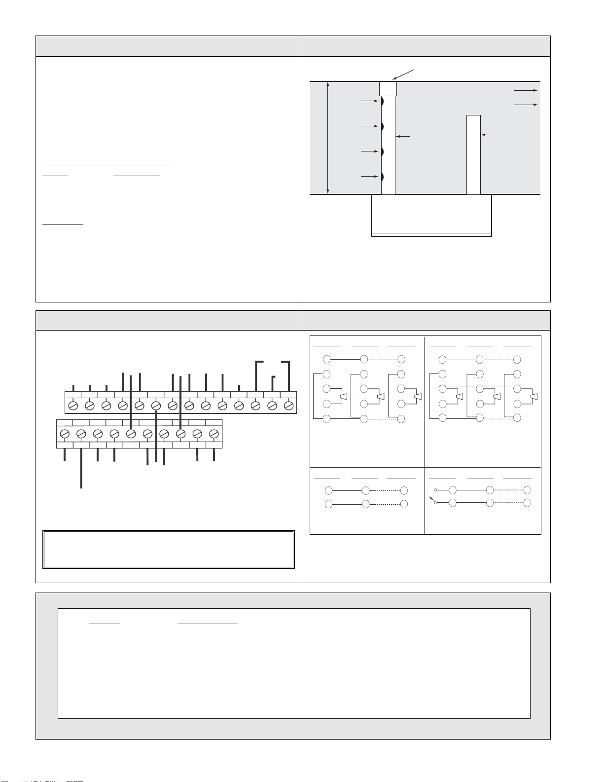
The SL-2000 Series is designed to operate in duct
widths from 12.0" to 10.0' (30.5 cm to 3.05m) with an air
velocity from 100-4000 fpm (0.5-20.3 mps). The
SL-2000 Series will operate on any one of four input
voltages: 24 VAC, 24 VDC, 115 VAC, or 230 VAC. It
uses either a photoelectric or ionization smoke detector
head. Each detector contains two Form C and one Form
A alarm contact, which transfer in the event of smoke.
There is also one trouble contact, which supervises the
presence of input power and removal of the detector
head. A manual test/reset switch and visual indicators of
pilot and alarm are provided on the front of the detector.
Up to 30 SL-2000 Series units may be wired to use a
common test/reset function and to alarm simultaneously
when a single unit alarms.
Power requirements
50/60 Hz (without
accessories) 24 VAC @ 55 mA standby,
190 mA alarm
24 VDC @ 15 mA standby,
70 mA alarm
115 VAC @ 16 mA standby,
32 mA alarm
230 VAC @ 10 mA standby,
20 mA alarm
Relay contact rating
Alarm (2) SPDT, 10A, 115 VAC, resistive
Alarm (1) SPST-NO, 2A, 115 VAC,
resistive
Trouble (1) SPDT, 10A, 115 VAC, resistive
Radioactive element For SL-2000-N only
Americium 241, 0.9 µCi
Air velocity 100-4000 fpm (0.5-20.3 mps)
Approvals
UL 268A; UROX.S2829
CSFM 3240-1004:105
MEA 73-92-E, Vol. 27
Ambient temp
SL-2000-N 32° to 155°F (0° to 68°C)
SL-2000-P 32° to 100°F (0° to 38°C)
Humidity 10% to 85% RH noncondensing
Material Gray plastic back box,
clear plastic cover
Weight 2.5 lb (1.13 kg)
Mounting 7" (17.8 cm) exhaust tube, sampling
tube end cap, mounting template
and hardware supplied
Dimensions 13.5"L x 4.5"H x 2.25"D
(34.3 x 11.4 x 5.7 cm)
FEATURES
• Low flow technology, 100-4000 fpm
• Universal voltage: 24 VAC, 24 VDC, 115 VAC, or
230 VAC
• Two Form C and one Form A alarm contacts and
one trouble contact
• Interchangeable "plug-in" photoelectric or ioniza-
tion heads
• Compatible with building automation and fire
alarm systems
• Dust filtering included in detector head
• Interconnect up to 30 detectors for common
functions
• Compatible with MS Series Remote Accessories
• Cover removal trouble indication
• Magnet test capability
• Front or rear loading sampling tubes
• Optional weatherproof enclosure
SPECIFICATIONS
SL-2000
April 2004

KELE • www.kele.com • FAX 800-284-5353 USA 888-397-5353 • International 901-382-6084
Red Stopper
Air Flow
Intake
Tube
(order
separately)
Exhaust
Tube
(provided)
Top of Detector
Entire Width
of Duct
(+) PILOT OUT
10A
ALARM
CONTACT
123456789
10 G220 115 H
11 12 13 14 15 16 17 18 19 20
GROUND
(-) COMM
10A
*TROUBLE
CONTACTS
NO
POWER
INPUT
24
VAC/VDC
10A
ALARM
CONTACT
NC
NC NO (-) (+)
C
C
POWER
INPUT
220/240
VAC
120
VAC
NC NO
C
C
NO
CONNECTION
INTERCONNECT
ALARM LINK
(-) (+)
AUX
POWER
OUT
2A
ALARM
CONTACT
NO
RESET INPUT
*Trouble contacts are shown in non-energized condition. Under normal operation
contacts will be reversed.
-BLK
1
20
1
20
1
20
12
20
12
20
12
20
14
19
1313
14
19
20
13
14
19
20
All alarm relays operate with single alarm
Individual horn/strobe operate on alarmed
detector only
30 detectors max
All alarm relays operate with single alarm
30 detectors max
Common test/reset
30 detectors max
All alarm relays operate with single alarm
All horns/strobes operate with single alarm
10 detectors max
Normally
open reset
switch
Detector #1
12 12 12 12 12 12
+ RED
-BLK
+ RED
-BLK
+ RED
-BLK
13
14
19
20
13
14
19
20
13
14
19
20
+ RED
-BLK
+ RED
-BLK
+ RED
Detector #2 Detector #30 Detector #1 Detector #2 Detector #10
Detector #1 Detector #2 Detector #30 Detector #1 Detector #2 Detector #30
20
H H H H H H
MOUNTING
MODEL DESCRIPTION
SL-2000-N Ionization Duct Smoke Detector for 24 VAC, 24 VDC, 115 VAC, 230 VAC
SL-2000-P Photoelectric Duct Smoke Detector for 24 VAC, 24 VDC, 115 VAC, 230 VAC
STN-2.5 Sampling Tube for 1.0' to 2.5' (0.3 to 0.7m) Duct Widths
STN-5.0 Sampling Tube for 2.5' to 5.0' (0.7 to 1.5m) Duct Widths
STN-10.0 Sampling Tube for 5.0' to 10.0' (1.5 to 3m) Duct Widths
WP-2000 NEMA Type 3R Enclosure 11.06" x 18.13" x 4.38" (28.1 x 46.0 x 11.2 cm)
55000-250APO Replacement Ionization Smoke Detector Head Only
55000-350APO Replacement Photoelectric Smoke Detector Head Only
ORDERING INFORMATION
WIRING INTERCONNECTING WIRING
Mount the detector in an air duct using the provided template and
sheet metal screws. Detector should be mounted at least six
duct widths from the fan or other sources of turbulence with air-
flow from 100-4000 fpm (0.5-20.3 mps). The intake sampling
tube has holes drilled the entire length of the tube and should
extend the entire width of the duct, with the end opposite the
detector capped. The holes must be facing into the air flow (see
Figure 1 to the right). The exhaust tube is a piece of steel piping
approximately 7"Long (17.8 cm).
Intake Sampling Tube Lengths
Model Duct Width
STN-2.5 1.0' to 2.5' (0.3 to 0.7m)
STN-5.0 2.5' to 5.0' (0.7 to 1.5m)
STN-10.0 5.0' to 10.0' (1.5 to 3m)
Important
For the correct installation, testing and maintenance of a duct
smoke detector, follow the instructions provided with the detec-
tor and refer to your locally enforced fire, mechanical, and/or
building codes. Please also review NFPA 72 (National Fire
Alarm Code) and NFPA 90A (Standard for Installation of Air
Condition and Ventilation Systems). Your local Authority Having
Jurisdiction (AHJ) should also be consulted.
Note: Sampling tubes over 3' (0.9m) must be supported on the
opposite side of the duct from the detector.
FIGURE 1. TYPICAL DUCT INSTALLATION
CAUTION: For terminals (7, 8, 18), (6, 16, 17), (13, 14) do not
use looped wire under terminals. Break wire run to provide
supervision of connections. NOTE: When using detector interconnection functions, wire all
detectors to a common power source. Use of multiple power sources
for interconnected detectors may cause damage to the detectors
and/or may prevent the detectors from functioning properly.
Popular Smoke Alarm manuals by other brands

System Sensor
System Sensor 2151 Installation and maintenance instructions

Universal Security Instruments
Universal Security Instruments MC304S manual

Allterco Robotics
Allterco Robotics SHELLY PLUS SMOKE Networking guide

VESDA
VESDA LaserSCANNER VLS-200 installation manual

Kidde
Kidde 5Y29 user guide

System Sensor
System Sensor FAAST user guide