**Effective Intensity Requirements for Sleeping Area
isible Notification Appliance
Distance from Ceiling to Top of Lens Intensity
greater than or equal to 24" (610mm) 110 Cd
less than 24" (610mm) 177 Cd
GXS REMOTE STROBE
UL 1971 COMPLIANT
Installation Instructions-Owner's Information
I. INTRODUCTION
The entex model XS Remote Strobe is a high quality remote visible signaling appliance. The
high-intensity strobe utilizes a Xenon flash tube which generates a high-intensity light, visible
from all sides of the lens. The XS Remote Strobe is intended to provide a visible notification
signal for the purpose of life safety and property protection. This appliance is ideal for hotels,
apartments, hospitals, rest homes or wherever dependable visible alarms are required. This
appliance is listed in compliance with UL 1971, Signaling Appliances For The Hearing Impaired.
II. LOCATION
This appliance is intended for use in Fire Alarm Systems and is to be installed in accordance with
this installation manual, the recommendation of the local authorities having jurisdiction, and other
NFPA Standards that provide standards on notification appliances for protective signaling
systems. The entex XS Remote Strobe is intended for indoor installation only and is not
listed for outdoor or drip proof applications.
Wall-mounted appliances shall have their bottoms at heights above the finished floor of not less
than 80 in. (2m) and no greater than 96 in. (2.4m)**. Spacing shall be in accordance with Table
A. If a room configuration is not square, the room size that will entirely encompass the room or
subdivide the room into multiple squares shall be used.
WARNING! Visual signal must be in the direct viewing area of the occupant in order to be seen.
WARNING! Visual signal can not be seen when objects such as doors, furniture or walls block
visual signal.
NOTICE: Visual signals for the hearing impaired are only one method of alerting the hearing
impaired. Visual signals may not be the preferred method for notifying all hearing
impaired individuals.
For a period of 36 months from the date of purchase, or a maximum of
42 months from the date of manufacture, entex warrants to you, the
original purchaser, that your appliance will be free from defects in
workmanship, materials, and construction under normal use and
service. If a defect in workmanship, materials, or construction should
cause your appliance to become inoperable within the warranty period,
entex will repair your appliance or furnish you with a new or rebuilt
replacement appliance without charge to you except for postage required
to return the appliance to us. entex will not reimburse you for repairs or
replacement parts provided by other parties. Your repaired or replace-
ment appliance will be returned to you free of charge and it will be cov-
ered under this warranty for the balance of the warranty period.
This warranty is void if our inspection of your appliance shows that the
damage or failure was caused by abuse, misuse, abnormal usage, faulty
installation, improper maintenance, or repairs other than those performed
by us.
ANY WARRANTIES IMPLIED UNDER ANY STATE LAW,
INCLUDIN IMPLIED WARRANTIES OF MERCHANTABILITY OR
FITNESS FOR A PARTICULAR PURPOSE, APPLY ONLY FOR THE
WARRANTY PERIOD SPECIFIED ABOVE. PLEASE NOTE THAT
SOME STATES DO NOT ALLOW LIMITATIONS ON HOW LON AN
IMPLIED WARRANTY LASTS, SO THE ABOVE EXCLUSION MAY NOT
APPLY TO YOU.
ENTEX WILL NOT BE LIABLE FOR ANY LOSS, DAMA E,
INCIDENTAL OR CONSEQUENTIAL DAMA ES OF ANY KIND
ARISIN IN CONNECTION WITH THE SALE, USE OR REPAIR OF
THIS APPLIANCE. THE MAXIMUM LIABILITY OF ENTEX SHALL
NOT IN ANY CASE EXCEED THE PURCHASE PRICE PAID BY YOU
FOR THE APPLIANCE. PLEASE NOTE THAT SOME STATES DO NOT
ALLOW THE EXCLUSION OR LIMITATION OF INCIDENTAL OR CON-
SEQUENTIAL DAMA ES, SO THE ABOVE EXCLUSION MAY NOT
APPLY TO YOU.
If a defect in workmanship, materials, or construction should cause
your appliance to become inoperable within the warranty period, you
must return the appliance to entex postage prepaid. You must also
prove to the satisfaction of entex the date of purchase of your
appliance. Warranty service may only be performed by entex
personnel at entex's facilities in Zeeland, Michigan. You must also pack
the appliance to minimize the risk of it being damaged in transit. You
must also enclose a return address. Appliances returned for
warranty service should be sent to: entex Corporation, 10985 Chicago
Drive, Zeeland, MI 49464. If we receive an appliance in a damaged
condition as the result of shipping, we will notify you and you must file a
claim with the shipper.
THIS WARRANTY IVES YOU SPECIFIC LE AL RI HTS AND YOU
MAY ALSO HAVE OTHER RI HTS WHICH VARY FROM STATE TO
STATE.
ENTEX CORPORATION
10985 CHICA O DRIVE, ZEELAND, MI 49464
PHONE: 800-436-8391
www.gentex.com
550-101-T
6-1-93
LIMITED WARRANTY
Note: AC Voltage Range Limits: 96-132v. This product was only tested to the stated voltage
range; do not apply 80% and 110% of this range for system operation.
NA = Not Allowable
Important Notice:
These materials have been prepared by entex Corporation (" entex") for informational purposes only, are necessarily summary, and are not purported to
serve as legal advice and should not be used as such. entex makes no representations and warranties, express or implied, that these materials are
complete and accurate, up-to-date, or in compliance with all relevant local, state and federal laws, regulations and rules. The materials do not address all
legal considerations as there is inevitable uncertainty regarding interpretation of laws, regulations and rules and the application of such laws, regulations
and rules to particular fact patterns. Each person's activities can differently affect the obligations that exist under applicable laws, regulations or rules.
Therefore, these materials should be used only for informational purposes and should not be used as a substitute for seeking professional legal advice.
entex will not be responsible for any action or failure to act in reliance upon the information contained in this material.
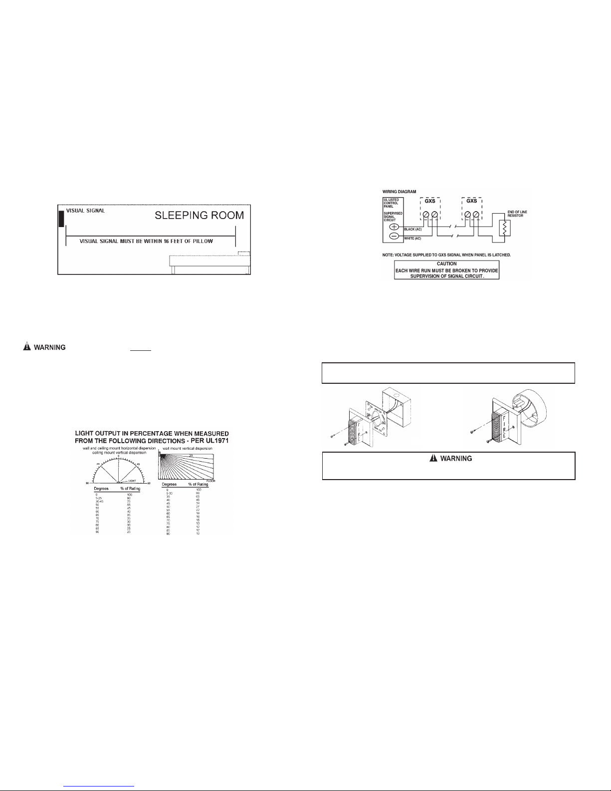
WARNING! isual signal must be installed within 16 feet of the pillow when
used in a sleeping area.
REMOTE ISIBLE SIGNALING APPLIANCE
Table A
I. CLEANING AND MAINTENANCE
Each notification signaling appliance should be maintained in reliable operating condition.
Periodic inspections and tests should be made to assure proper operation of the appliances.
Visible appliances may require periodic cleaning to remove dust or debris that may have
accumulated on the appliance. The frequency of cleaning will depend on the local ambient
conditions.
II. TO RETURN A GXS REMOTE STROBE UNIT
Should you experience problems with your XS Remote Strobe unit, proceed as follows.
1. Turn off electrical power to the auxiliary alarm circuit.
2. Unscrew the unit from the electrical box.
3. Disconnect the unit from the field wiring. Reconnect the two hot supply voltage circuits (black
wires) and the two neutral supply voltage circuits (white wires) for AC Models of the auxiliary
alarm circuit to maintain power to the other auxiliary alarm appliances in the system.
4. Carefully pack the defective unit (the manufacturer cannot be responsible for consequential
damage due to shipping or mishandling). Include your return address and complete details
as to the nature of the difficulties being experienced and date of installation.
5. Return to: entex Corporation, 10985 Chicago Drive, Zeeland, MI 49464. Prior to returning,
call
the
entex
field
service
department
at
1-800-436-8391
or
e-mail
[email protected]for a RMA number.
III. ELECTRICAL SPECIFICATIONS
WALL STROBE CURRENT RATIN S
Candela Regulated 120VAC
Max. Operating Current(mA)
177 209
550-0101
Page 1
Room Spacing for Wall-Mounted Visible Appliances per NFPA 72, 2007 Edition
Maximum Room Size Minimum Required Light Output ( Effective Intensity, Cd)
Meters Feet One Light per
Room
Two Lights per Room
(Located on Opposite Walls)
Four Lights per Room (One
Light per Wall)
6.10 x 6.10 20 x 20 15 NA NA
8.53 x 8.53 28 x 28 30 Unknown NA
9.14 x 9.14 30 x 30 34 15 NA
12.2 x 12.2 40 x 40 60 30 15
13.7 x 13.7 45 x 45 75 Unknown 19
15.2 x 15.2 50 x 50 94 60 30
16.5 x 16.5 54 x 54 110 Unknown 30
16.8 x 16.8 55 x 55 115 Unknown 28
18.3 x 18.3 60 x 60 135 95 30
19.2 x 19.2 63 x 63 150 Unknown 37
20.7 x 20.7 68 x 68 177 Unknown 43
21.3 x 21.3 70 x 70 184 95 60
24.4 x 24.4 80 x 80 240 135 60
27.4 x 27.4 90 x 90 304 185 95
30.5 x 30.5 100 x 100 375 240 95
33.5 x 33.5 110 x 110 455 240 135
36.6 x 36.6 120 x 120 540 305 135
39.6 x 39.6 130 x 130 635 375 185
Page 4
THIS APPLIANCE WILL NOT OPERATE WITHOUT ELECTRICAL POWER. AS FIRES
FREQUENTLY CAUSE POWER INTERRUPTIONS, ENTEX SU ESTS YOU DISCUSS
FURTHER SAFE UARDS WITH YOUR LOCAL FIRE PROTECTION SPECIALIST.