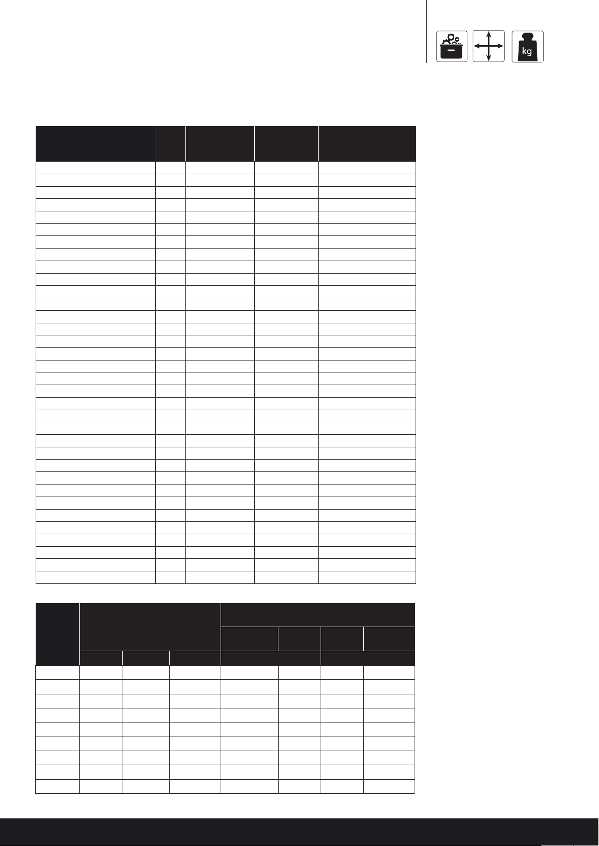
Kelvion TEC1 Maintenance and service guide

Kelvion Commercial Coolers
INSTALLATION & MAINTENANCE
Health, Safety & Warranty Procedure
Parts & Spares
Dimensions
Weight
Installation
Fanset
Wiring & Control options
CONTENT
KG

HEALTH AND SAFETY INSTRUCTION AND SIGNS
This concerns the following hazards, which may be encountered when installing and maintaining this equipment:
CAUTION
All work on the units must be carried out by a qualified engineer in accordance to all applicable codes, ordinances, laws
and local by-laws. Installation and maintenance manual must be kept with unit at all times. Ensure that instruction manual
is understood before installation Ensure working environment is suitable.
Use suitable PPE (Personal Protection Equipment) as per site regulations and as appropriate for the task. It is the responsibility of the person
performing the task and their employer to ensure that all suitable PPE is provided and worn at all times. Detailed below is some of the suggest-
ed PPE during installation and commissioning of the unit.
Head protection Foot protection Hand protection High visibility clothing Eye protection
BEFORE INSTALLATION
ELECTRICAL VOLTAGE
ENSURE THAT
1. The power supply is isolated before any installation or maintenance work is carried out.
2. The voltage, working fluid and the maximum working pressure stated on the product nameplate is suitable for the
working environment.
PROTECTIVE CLOTHING
Sharp edges on the casework of the units and coil fins are a possible cause of cuts to fingers and hands.
Appropriate protective clothing /gloves should always be worn.
ENSURE THAT:
• The proposed method of mounting is adequate to support the total operational weight (including frost & ice) of the unit. ‘Dry Weights’ are
given on the nameplate and the product sheet.
• Nameplate Data: When further pressure tests are carried out, the pressure applied shall not exceed 1.3 times the maximum operating
pressure given on the nameplate.
• When ancillary pressure equipment is supplied with a unit, but not a pipe to it, the parts must be treated as separate components and
data taken from individual nameplates.
• Rotating blades – dangling items of clothing, jewellery or any items that could be pulled into the fan set are a hazard. Keep safe working
distance from the fan plate.
• The fan guard should not be removed nor should the fan set be removed from the unit.
DURING INSTALLATION AND MAINTENANCE ENSURE THAT:
• The unit is installed and maintained by qualified personnel only.
• The temperature of coils with vinyl-coated fins does not exceed 150°C (e.g. during brazing), as toxic fumes would be produced.
BE AWARE OF BURN HAZARD:
BURN HAZARDS
1. Burn hazards from pipes and pipeline components when the heat exchanger temperature exceeds 60°C.
2. Burn caused by refrigerant coming into contact with the skin or eyes.

3
WARRANTY PROCEDURE
This warranty applies to evaporator models TEC, KEC and KME unless otherwise stated in product literature or specific contracts, provides for a
manufacturers guarantee of twenty four months from date of dispatch against faults in workmanship or material. For further details please refer
to Kelvion Terms and Conditions of Sales.
When submitting a warranty claim the following information is required:
• Customer’s original reference number job / order number.
• Kelvion ’s job number / advice note number.
• Type of unit and serial number.
• Date of installation.
• Details of defect.
• Date of delivery & installation
WHEN PROVIDING DETAILS OF THE DEFECT, PLEASE GIVE AS MUCH INFORMATION AS POSSIBLE
Was the unit satisfactory on delivery?
Frequency of fault (continuous / intermittent)
Is the unit leaking ? (+ location of leak)
ITEMS MANUFACTURED BY KELVION:
No work should be undertaken to resolve the problem either by the customer or a 3rd party until written approved by Kelvion - failure to do so will
invalidate the warranty.
THE ITEM MAY BE REPLACED OR RECTIFIED IF THE GUARANTEE CLAIM IS VALID.
For items that have been installed, Kelvion have the right to decide if rectification on site is suitable and who should undertake the work or whether
to return / replace the unit(s). For items where Kelvion decides to replace, the original faulty item must be returned. All items which are returned will
be inspected. If the guarantee claim is not valid the customer will be advised and further instructions requested, either to return the item or to issue
an official order to replace or rectify the item. If you require a replacement product the buyer will be asked to supply a purchase order, products or
items must be returned to the customers cost. When the unit has been returned and evaluated, the buyer will be notified by Kelvion if the claim is
valid.
ITEMS NOT MANUFACTURED BY KELVION:
• After order has been placed the item will be replaced and the customer will be invoiced
• The item will be returned to the supplier for evaluation.
• If the claim is valid the credit received from the supplier will be passed on to the customer.
INVALIDATION OF WARRANTY
Kelvion accepts no liability according to Kelvion’s terms and conditions of sale, or for loss or damage arising as a result of:
1. Failure to install set up or put to work any part of the equipment in the manner specied in the Installation and Maintenance Instruc tions.
2. Failure to maintain the equipment in the manner specied in the Installation and Maintenance Instructions.
3. Replacement parts, additional parts or accessories manufactured by persons other than Kelvion having been incorporated into, or attached to the equipment.
4. The equipment having been adapted for use, operated or used in such a way as does conform to Kelvion’s recommendation.
5. Equipment or items not returned within 15 days of initial claim.
DELIVERY & INSPECTION
All equipment should be inspected, on delivery, for any signs of visible/concealed damage or missing items. Any damage or missing items should be noted on the
carrier’s documentation when signing for the goods.
It is the responsibility of the buyer to claim against the carrier for damage, concealed damage or missing items occurring during transportation.

TEC SPARES PARTS & DIMENSIONS
15
////
(378mm) Casework
TEC1 - TEC5, TEC7
8
////
(210mm)
3/4
////
D/CONN
TEC1 - TEC5, TEC7
15
////
(378mm) Casework
10
////
(260.5mm)
3/4
////
D/CONN
A- Casework
B
C

5
TEC SPARES QTY.
PER
PART
NUMBER
SAP
NUMBER USED ON
Fanset 230mm EC Single Phase SPR-TECFAN-Z 100513585 TEC
Fan Plate / Drain Pan 1 TEC-112-202-1 100513726 TEC1,2
Fan Plate / Drain Pan 1 TEC-113-202-1 100513731 TEC3
Fan Plate / Drain Pan 1 TEC-113-203-1 100513733 TEC3-5
Fan Plate / Drain Pan 1 TEC-114-202-1 100513742 TEC4
Fan Plate / Drain Pan 1 TEC-115-202-1 100513746 TEC5
Fan Plate / Drain Pan 1 TEC-116-202-1 100513753 TEC6
Fan Plate / Drain Pan 1 TEC-117-202-1 100513757 TEC7
Fan Plate / Drain Pan 1 TEC-118-202-1 100513761 TEC8
Defrost Element 275W 1 215-230-201 100461647 T1-LTKIT
Defrost Element 550W 1 215-250-601 100461654 T2-LTKIT
Defrost Element 700W 1 215-250-701 100461655 T3-LTKIT
Defrost Element 900W 1 215-250-901 100461657 T3.5/4-LTKIT
Defrost Element 1000W 1 215-251-001 100461659 T5/6-LTKIT
Defrost Element 1400W 1 215-251-401 100461661 T7/8-LTKIT
Defrost Element 250W 2 215-260-301 100461662 WT1/2-LTKIT
Defrost Element 325W 2 215-260-302 100461663 WT3-LTKIT
Defrost Element 425W 2 215-260-401 100461664 WT3.5/4-LTKIT
Defrost Element 575W 2 215-260-601 100461668 WT5-LTKIT
Defrost Element 675W 2 215-260-701 100461671 WT6-LTKIT
Defrost Element 470W 4 215-415-001 100461716 WT7/8-LTKIT
Heater Clip 2 227-762-021 100463280 T1-LTKIT
Heater Clip 2 227-762-016 T2-LTKIT-T7/8-LTKIT
Heater Clip 2 227-762-019 100463277 All WT-LTKIT
Drain Tray Heater Guard 112-127 100457825 WT1/2
Drain Tray Heater Guard 113-127 100457879 WT3
Drain Tray Heater Guard 114-127 100457900 WT3.5/4
Drain Tray Heater Guard 115-127 100457938 WT5/6
Drain Tray Heater Guard 117-127 100457993 WT7/8
Drain Connection 1" BSP 261-763-001 Pre-1999
Drain Connection 1" BSP 261-463-008 Pre-1999
Gasket 1" 248-811-002 100465076 Pre-1999
Drain Connection 3/4" BSP 261-763-006 100465377
Gasket 3/4" 261-763-007
UNIT DIMENSIONS (mm)
WEIGHTS (APPROX)
Kg
REF
CHARGE WEIGHT REF
CHARGE WEIGHT
A B C 7 FPI (3.6mm) 5 FPI (5.1mm)
TEC1 525 262 453 0.1 70.1 7
TEC2 525 262 453 0.3 80.3 8
TEC3 690 345 618 0.5 12 0.5 12
TEC3.5 865 432 793 0.4 10 0.4 10
TEC4 865 850 793 0.5 14 0.5 14
TEC5 1120 560 524 0.6 16 0.6 16
TEC6 1120 560 524 0.8 19 0.8 19
TEC7 1528 764 728 0.8 24 0.8 24
TEC8 1528 764 1805 1.1 27 1.1 27

KEC SPARES PARTS & DIMENSIONS
444 Casework 275 MIN
460 D/PAN
413
461 O/A HEIGHT
393
AO/A LENGTH
B- CASEWORK
C- D/PAN
1
////
D/CONN 1.8
////
524 O/A WIDTH
489 MTG CTRS
D- MTG CTRS
46
30
25
MONOBOLT FAN
PLATE TO
TOP PLATE (3 OFF
MONOBOLTS)
RIVET FAN ORIFICE
TO FANPLATE
(AL RIVETS - 4 PER
ORIFICE)
FIT FANSET
(M4 FIXINGS -
4 PER FAN)
MONOBOLT FAN PLATE TO
BOTTOM PLATE
(5 OFF MONOBOLTS)
ALUMINIUM RIVETS TO BE
USED TO FIX BOTTOM PLATE
DRAIN PAN FITTED LOOSE FOR
TRANSPORT.
PLACE 4 x M6 FIXINGS IN A BAG
WITH DRAIN CONN & WASHER.
FIT BAG AT HEADER END SO IT
IS VISIBLE THROUGH CLOSING
PLATE HOLES.
REAR HANGING BRACKETS TO BE
INITIALLY FITTED WITH TOP
MONOBOLT ONLY.
2ND FIXING TO BE FITTED WITH REAR
CLOSING PLATE AND WILL FIX BOTH
HANGING BRACKET AND CLOSING
PLATE
50

7
SPARES PART
NUMBER
SAP
NUMBER USED ON
FAN SET 300mm 238-9030-0121 100464933 KEC10/15/20/35
FAN SET 3230V/115V-1ph 238-9030-0321 100464934 KEC25/30/40/
45/55/70
FAN SET 300mm 231-9030-0121 100464214 KEC10/15/20/35
FAN SET 300mm 231-9030-0321 100464215 KEC25/30/40/45/55/70
DRAIN CONN 1inBSP 261-763-001 All Models
SEALING WASHER FOR 1"BSP D/CONN 248-811-002 100465076 All Models
DEFROST ELEMENTS
HTR DEF 170W 115V STRT 440mm hot L 215-410-340 100461705 KEC10/15
HTR DEF 230W 115V STRT 590mm hot L 215-410-460 100461708 KEC20/25/30
HTR DEF 400W 115V STRT 1.08m hot L 215-410-790 100461711 KEC35/40/45
HTR DEF 600W 115V STRT 1.54m hot L 215-411-200 100461715 KEC55/70
COIL HTR RETAINING CLAMP UKEC RANGE 227-762-027 100463286 All Models
END COVER 19-009 100458624 All Models
DRAIN PAN - CASE 400 19-034 100458790 KEC10/15
DRAIN PAN - CASE 550 19-036 100458825 KEC20/25/30
DRAIN PAN - CASE 1000 19-039 100458830 KEC35/40/45
DRAIN PAN - CASE 1500 19-040 100458835 KEC55/70
TABLE A:
UNIT FAN SET SAP
NUMBER J/BOX SAP
NUMBER
KEC10 231-9030-0121 100464214 218-901-013 100462723
KEC15 231-9030-0121 100464214 218-901-013 100462723
KEC20 231-9030-0121 100464214 218-901-013 100462723
KEC25 231-9030-0321 100464214 218-901-013 100462723
KEC30 231-9030-0321 100464214 218-901-013 100462723
KEC35 238-9030-0121 100464933 218-901-015 100462729
KEC40 238-9030-0321 100464933 218-901-014 100462724
KEC45 238-9030-0321 100464933 218-901-014 100462724
KEC55 231-9030-0321 100464933 218-901-013 100462723
KEC70 231-9030-0321 100464933 218-901-013 100462723
UNIT
DIMENSIONS
mm
WEIGHTS (APPROX)
Kg
REF
CHARGE WEIGHT
A B C D 6 FPI, 4 FPI, 3 FPI
KEC10 726mm 700mm 705mm 435mm 0.5Kg 27Kg
KEC15 726mm 700mm 705mm 435mm 0.6Kg 28Kg
KEC20 876mm 850mm 855mm 585mm 0.8Kg 33Kg
KEC25 876mm 850mm 855mm 585mm 0.8Kg 33Kg
KEC30 876mm 850mm 855mm 585mm 1.2Kg 35Kg
KEC35 1326mm 1300mm 1305mm 1035mm 1.4Kg 47Kg
KEC40 1326mm 1300mm 1305mm 1035mm 1.4Kg 47Kg
KEC45 1326mm 1300mm 1305mm 1035mm 2.1Kg 53Kg
KEC55 1826mm 1800mm 1805mm 1535mm 2.0Kg 67Kg
lbs

532.5 O/A
446.5
409.5
555
574.9
KME SPARES PARTS & DIMENSIONS
60
MOUNTING CTRS
17.5
A - MIN
KME 50 - 175
146
B - O/A
D - D/PAN
COIL CONNS END
1
////
D/CONN
ELEC CONNS END
C - MOUNTING CTRS
146
53
MOUNTING
BRACKET DETAIL
SLOT 13W X 25L
46
30.4

9
SPARES PART
NUMBER
SAP
NUMBER USED ON
FANSET 400mm 480V-
3PH 231-9040-0443 100464229 KME
FAN SET 400mm
230V- 1PH 231-9040-0421 100464227 KME
Drain Connection (1"
BSP) 261-763-001 100465376 All Models
Drain Connection
Gasket 248-811-002 100465076 All Models
Axial Fan Set 26°Pitch,
415V, 3Ph, 50Hz 231-845-261 100464139 All Models
Motor 231-845-261-MTR 100464141 All Models
Impeller 231-845-261-IMP All Models
Fan Guard 231-845-261-GUARD 100464140 All Models
380/465V, 3Ph, 60Hz,
Aerofoil Fan Set 231-845-161 All Models
Motor 231-845-161-MTR All Models
Impeller 231-845-161-IMP All Models
Fan Guard 231-845-161-GUARD All Models
220/240V, 1Ph,
50/60Hz, Aerofoil
Fan Set
293-400-106 All Models
Motor 293-400-106-MTR All Models
Impeller 293-400-106-IMP All Models
Fan Guard 293-400-106-GUARD 100532012 All Models
DEFROST ELEMENTS (Coil heaters)
530W 230V U Bend 215-260-440 100461666 KME50
800W 230V U Bend 215-260-660 100461670 KME60
1060W 230V U Bend 215-261-080 100461675 KME80, 95
800W 115V Straight 215-410-800 100461712 KME115, 140
940W 115V Straight 215-410-940 100461714 KME175
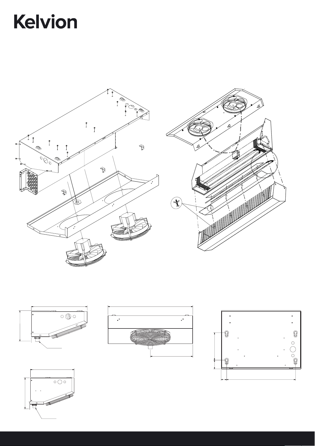
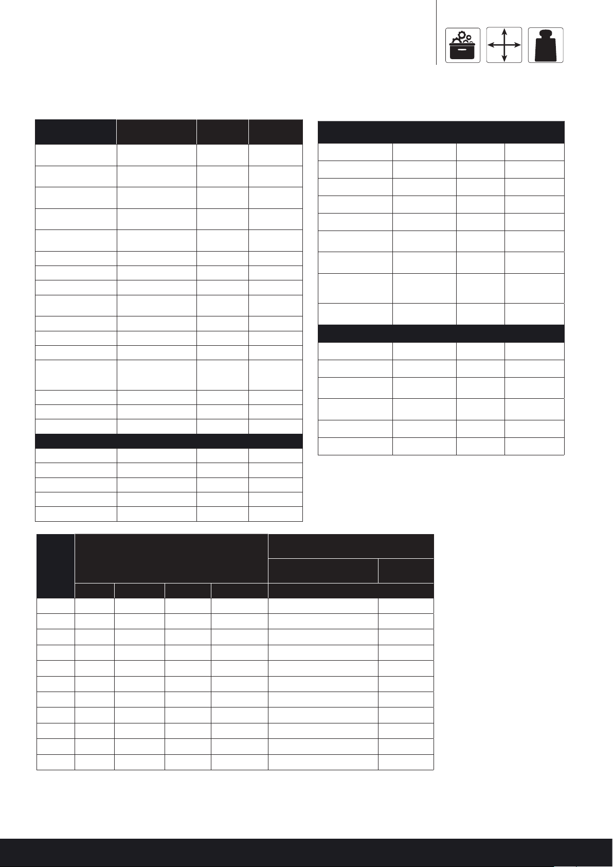
UNIT
DIMENSIONS
mm
WEIGHTS (APPROX)
Kg
REF
CHARGE WEIGHT
A B C D 6 FPI, 4 FPI, 3 FPI
KME50 350mm 1007mm 715mm 1011mm 2.1Kg 85Kg
KME60 350mm 1332mm 1040mm 1336mm 2.9Kg 112Kg
KME80 400mm 1682mm 1390mm 1686mm 2.6Kg 129Kg
KME95 450mm 1682mm 1390mm 1686mm 3.9Kg 139Kg
KME115 500mm 2357mm 2065mm 2361mm 3.8Kg 170Kg
KME140 500mm 2357mm 2065mm 2361mm 5.6Kg 195Kg
KME175 500mm 2732mm 2440mm 2736mm 6.6Kg 217Kg
KME232 650mm 2357mm 2065mm 2361mm 8.0Kg 312Kg
KME282 650mm 2357mm 2065mm 2361mm 11.8Kg 346Kg
KME352 850mm 2732mm 2440mm 2736mm 14.1Kg 365Kg
KME353 850mm 2732mm 2440mm 2736mm 14.1Kg 406Kg
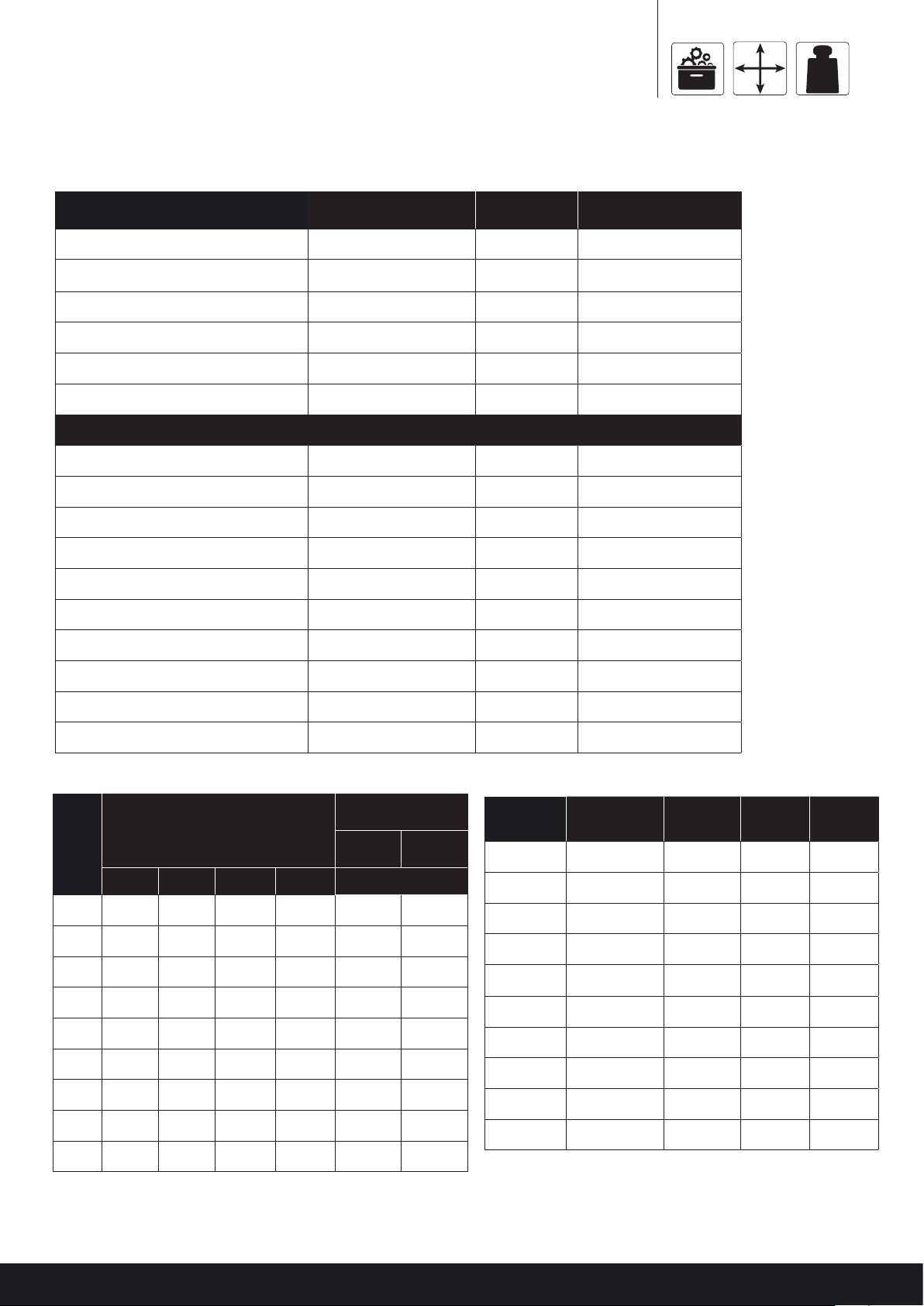
lbs
DEFROST ELEMENTS (Draintray)
265W 230V Straight 215-210-220 100461630 KME50
400W 230V Straight 215-210-330 100461631 KME60
530W 230V Straight 215-210-440 100461633 KME80, 95
800W 230V Straight 215-210-660 100461637 KME115, 140
940W 230V Straight 215-210-780 100461638 KME175
Peripheral Heater
300W 215-290-406 100461687 All Models
Peripheral Heater Kit SPR-290-505 100513470 KME Axial Fans
Only
Fanplate Heater
(Caution required
due to Plastic Guard)
215-290-201 100461686 All Models
Anticreep clips (1 per
coil heater) 227-762-025 100463285 All Models
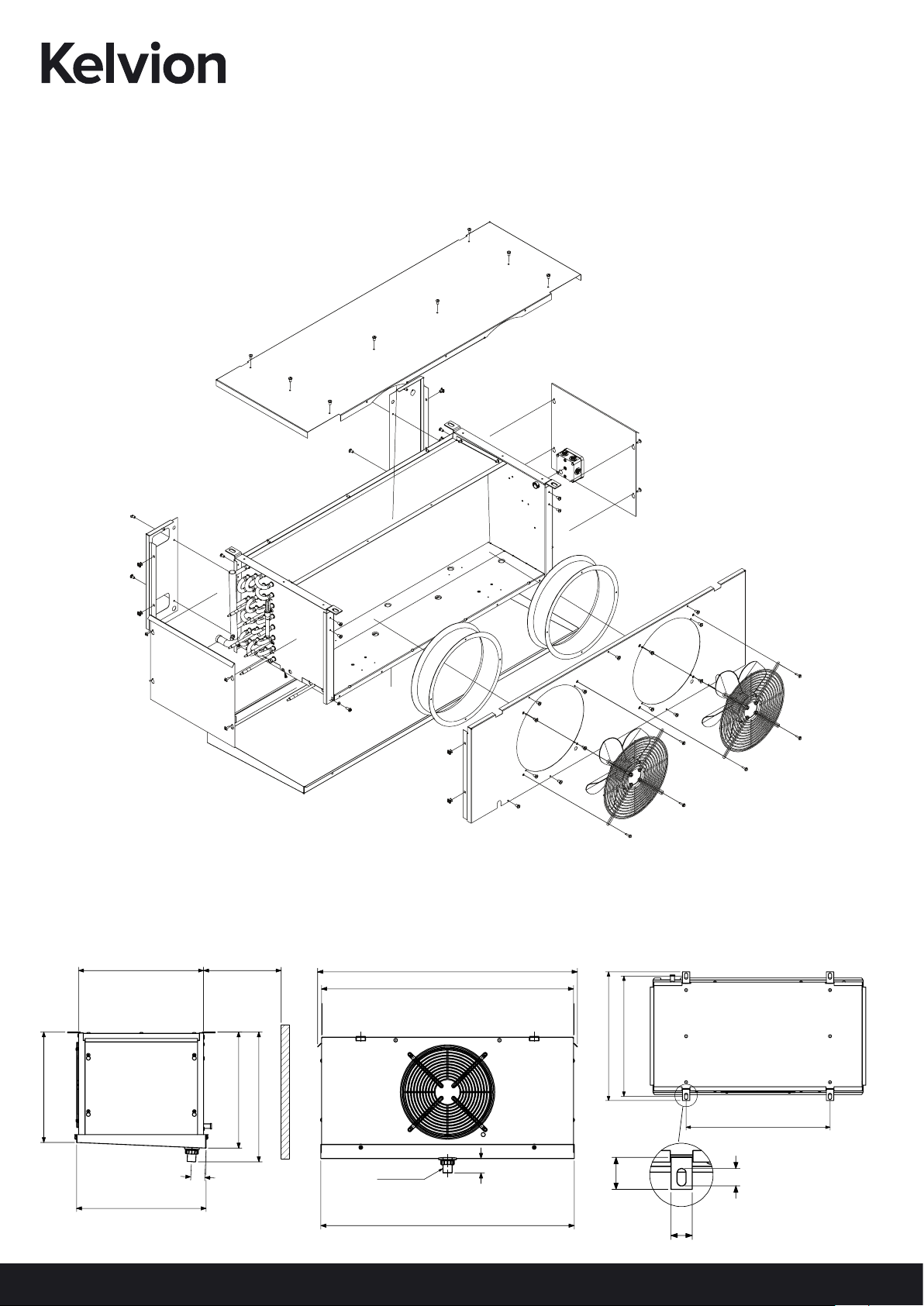
CASEWORK PARTS
Drain Pan 20-034 100459676 KME50
Drain Pan 20-035 100459681 UKME60
Drain Pan 20-036 100459686 KME80 /
KME95
Drain Pan 20-037 100459691 KME115 /
KME140
Drain Pan 20-038 100459696 KME175
End Cover 20-010 100459384 KME All Models

LABELLING ON UNITS
LABELLING ON ALL TEC, KEC & KME, UDSR MODELS
1
234
2
5
1. Kelvion logo 2. Danger and Caution labels 3. Pass label
4. Name Plate 5. Plate label Fork lift points
KKelvionelvion
KEC30-4L
44L L1Ph S3G
PI
1. Maximum operating pressure suitable for
this product.
2. Electrical supply information
3. Fluid working group. Reference to PED
classication, i.e. group 1 or group 2
4. Serial Number
1
2
3
1

11
Keep dry This way up Fragile Recycle Stacking
3

UNPACKING
UNPACKING ON ALL KEC AND KME MODELS
1. Remove the box/crate packaging.
2. On KEC units remove the drain tray by removing the four xings and then t the hexagonal drain connection and gasket into the hexagonal well inside the
drain tray. Hand tighten this assembly using the knurled nut on the outside. When the cooler is in position ensure that the drain pan is dropped down into the
operating position before tightening its xings. The KME units will have a cable tie xing the drain tray along the side of the unit.
3. Place into position using the location guidance.
UNPACKING ON ALLTEC MODELS
The location of the unit should be carefully selected to ensure that:
4. Air distribution from the cooler is not adversely eected by obstructions and is appropriate for the size and shape of the room, optimum air distribution
should be targeted. Product loading must be in accordance with good refrigeration practice.
5. Air entering the cooler is not obstructed.
6. The unit must be installed level in both directions.
7. Maintenance access should be considered when locating the product, including adequate space for heater withdrawal when appropriate.
8. The unit is not subjected to physical loads.
KEC / KME TEC

13
LOCATION GUIDANCE AND INSTALLATION
The location of the unit should be carefully selected to ensure that:
1. Air distribution from the cooler is not adversely aected by obstructions and is appropriate for the size and shape of the room, optimum air distribution
should be targeted. Product loading must be in accordance with good refrigeration practice.
2. Air entering the cooler is not obstructed.
3. The unit must be installed level in both directions.
4. Maintenance access should be considered when locating the product, including adequate space for heater withdrawal when appropriate.
5. The unit is not subjected to physical loads.
MODELS A
mm
B
mm
TEC all models 120 120
KEC all models 275 -
KME 50 , 60 350 -
KME 80, 95 450 -
KME 115, 140, 175 500 -
KME 232, 282 650
KME 352, 353 850
Air Flow
A
BAAir Flow
Air Flow
Air Flow
Air Flow

Nut
1” O.D Washer
MOUNTING THE UNIT
Evaporator Mounting
Bracket
1” O.D Washer
Nut
1-5/8” O.D Washer
Products
A
Free air discharge
1/4“ft drop per ft
Trap
Door and air curtain
Seal Required
Drain

15
L
L2 X L (min)
NOTE
• Do not mount evaporators above or adjacent to door.
• Do not restrict the air inlet (‘A’) to the evaporator .
• Air stream should be unobstructed by beams, lights or other store products (generally down aisles towards the door).
• Evaporators are designed to be ush and level ceiling mounted. Mounting rods and support structure should be designed to take the full operation weight
including tted accessories, refrigerant charge, ice and condensate .
Free Aisle

PIPEWORK
Pipework to and from the cooler should be suitable for:
• Working uid (guidance can be provided by Kelvion representative or pipe suppler)
• Atmospheric conditions
• Maximum operating pressure including relevant safety factor
Damage caused by incorrect installation will invalidate the
manufacturer’s warranty obligations.
Pipework to and from the coolers should be selected to suit the application and not the connection size of the unit. Pipework sizes should be selected to ensure
pressure drop does not exceed an equivalent of 2K at full load conditions.
Pipework should be supported independently from the cooler unit in a way that prevents the transmission of vibration to the units. A qualied engineer should
install the refrigerant pipework to a high standard of refrigeration practice. All pipework used must be clean and to refrigeration quality, all cuts should be made
using a pipe cutter, never a hacksaw, and care must be taken to remove all burrs and swarf.
Braze using silver bearing brazing rod and ensure that all joints are cleaned before brazing. During brazing care should be taken to ensure that all components
near joints should not be excessively overheated, a wet cloth should be applied where necessary. Dry nitrogen should be passed through the pipework during
brazing to minimise oxidisation.
WARNING!
Use appropriate PPE (personal protection equipment) during pipework, refrigerant charging and commissioning. During brazing ensure
the temperature of coils with vinyl coated ns does not exceed 300°F as toxic fumes would be produced . When brazing and leak testing
are complete the suction line should be insulated with 3/4” thick Class ‘O’ insulation. The unit has been thoroughly tested during
manufacture however after on site brazing is complete all pipework should be pressure tested for leaks to maximum of 1.3 capacity pressure
Be aware of the below hazards during pipework and refrigerant charging:
IN THE EVENT OF INJURY, SEEK MEDICAL ATTENTION IMMEDIATELY.
It is the responsibility of the installer to ensure piping to and from the condenser is suitable for the application, although guidance from your Kelvion
representative can be provided.
Unless otherwise specied, twin section units should be connected in parallel to each other, not in series; failure to do so will result in excessive uid pressure
drop and a corresponding loss in performance.
All pipework and ttings should be pressure tested upon installation completion in accordance with relevant regulations or legislations. Any pressure test should
not exceed the unit’s maximum operating pressure or the pressure rating of any safety devices.
Frost burns Cuts or WoundsHeat burns Inhalation

17
STORAGE
• To avoid contamination and corrosion, the units must be stored in dry and clean area.
• Storing for long periods is not recommended, but where this cannot be avoided the fan motors must run for a minimum of 2 hours per month. Failure to do
so will invalidate manufacturer’s warranty.
GENERAL
Upon receipt, the units should be visually inspected, any transport damage and / or missing parts must be recorded on the delivery note and the manufacturer
notied in writing within seven days. Please ensure:
• The pipework shows no signs of damage.
• The fan set / motor terminals box lids are not cracked or showing signs of obvious damage.
• The electrical screw terminals in control panels and motor mountings should be checked for security.
• Units are not portable and are only for permanent installation.
THE UNITS ARE DELIVERED WITH 0.35 BAR HOLDING CHARGE (N2) WHICH SHOULD BE SAFELY RELEASED THROUGH THE SCHRAEDER VALVE
ON THE SUCTION HEADER BEFORE REMOVING THE BRAZED HEADER / MANIFOLD CAPS.
• If the holding charge is not present the manufacturer should be contacted immediately.
• Units that have been packed in cardboard must be stored in a dry environment to prevent any water damage.
DAMAGE CAUSED BY INCORRECT INSTALLATION / UNIT MIS-HANDLING WILL INVALIDATE THE MANUFACTURERS WARRANTY
TEV SELECTION
It is important that the TEV is correctly sized and, for maximum performance, located within 100 mm of the distributor inlet. The TEV size should be determined
from manufacturer’s data using the maximum operational capacity and the minimum TEV pressure drop.
Externally equalised TEV must be used.
The minimum TEV pressure drop is the minimum condensing pressure minus the evaporator pressure and the distributor assembly pressure drop.
If the TEV is undersized or the condensing heat pressure fall below the minimum selected the evaporator pressure will drop causing ice build-up on the
evaporator coil.
DISTRIBUTOR ASSEMBLY PRESSURE DROP BAR
MODEL DISTRIBUTOR R134a R404A R407B/C R507
UKEC 10 to 55 1/2" 1.0 1.5 1.5 1.5
UKEC 70 5/8" 1.0 1.5 1.5 1.5
UKME 50 1/2" 1.0 1.5 1.5 1.5
UKME 60 to 95 5/8" 1.0 1.5 1.5 1.5
UKME 115 to 175 7/8" 2.0 2.96 2.96 2.96

ELECTRICAL VOLTAGE: Ensure that
1. The power supply is isolated before any installation or maintenance work is carried out.
2. T h e v o l t a g e , w o r k i n g u i d a n d t h e m a x i m u m w o r k i n g p r e s s u r e s t a t e d o n t h e p r o d u c t n a m e p l a t e i s s u i t a b l e f o r t h e w o r k i n g
environment.
3. All work must be carried out by a qualied electrical engineer in accordance with all local and national electrical codes.
ELECTRICAL INSTALLATION
TERMINAL BOX
Each unit is tted with a terminal box (es), tted on the right hand side when looking at the air discharge. Refrigeration connections are at the opposite end to
terminal box. Access to terminal box is via the unit end cover secured with four screws.
All eld wiring should be Copper and correctly sizes for the name plate current. Cable entry should be via knockouts provided and protected with a bush or
grommet.
Unit electrical schematic is secured to the inside of the terminal box or end cover.
MOTORS
All motors are EC (elec tronically commutated) and wired to the terminal box. Wires are xed to a screw or ‘cage clamp’ terminal strip.
DEFROST HEATERS
Defrost heaters, when tted, are stainless steel outer sheath terminated with a sealed black cable at the cold end. Depending on the model defrost heater will
the straight (linked pair) or ‘U’ shape. Heater are either secured to the inner drain tray or mounted in the evaporator coil and locked with a spring or retaining
clamp to prevent heater creep.
Heater withdrawal is via the connection end and requires a minimum 609mm clearance on KEC and 1219mm on UKME.
CLEANING - DANGER
Water or foam spray should not be directly sprayed at the motors or terminal box. Moisture ingress can result in failure or electrical short circuit.
CONTROL BOX
Remote control boxes (not supplied) should be located outside the cold room. Connecting wire should be adequately protected and sealed to prevent moisture
ingress.

19
WIRING DIAGRAMS
WIRING DIAGRAMS FOR KEC, KECX, KECP
KEC 10, 15 & 20 (FAN & DEFROST)
NOTE:
1. Supply 230V- 1PH 50/60Hz, 115V- 1PH 50/60Hz
2. Applies To UKEC Range Only:
• KEC 10 - Standard
• KEC 15 - Standard
• KEC 20 - Standard
3. High Speed: Connect Supply To
Terminal Block Terminals 1 and N.
4. Low speed: Link terminal block terminals 1 & 2
5. Defrost heaters (If required). Terminal Box: 218-901-013.
271-111-145
KEC 10, 15, 20, 25 & 30 (FAN & DEFROST)
NOTE:
1. Supply 230V- 1PH 50/60Hz, 115V- 1PH 50/60Hz
2. Applies To UKEC Range
3. (Single Fan Only):
• KEC 10 - Special
• KEC 15 - Special
• KEC 20 - Special
• KEC 25 - Special
• KEC 30 - Standard
• KEC 10 - Standard
4. Defrost Heaters (If Required).
5. Terminal Box: 218-901-013.
271-111-146

KEC 35 & 55 (FAN & DEFROST)
NOTE:
1. Fans Supply 230V- 1PH 50/60Hz, 115V- 1PH 50/60Hz
2. Applies to UKEC range only
• KEC 35 - Standard
• KEC 45 - Special
3. High Speed: Connect Supply To
Terminal Block Terminals 1 and N.
4. Low Speed: Link Terminal Block
Terminals 1 & 2.
5. Defrost heaters (if required).
6. Terminal Box: 218-901-015.
271-111-147
KEC 35, 40, 45, 55 & 70 (FAN & DEFROST)
NOTE:
1. Fans Supply 230V- 1PH 50/60Hz, 115V- 1PH 50/60Hz
2. Defrost Heaters Supply Option
3. 230V - 1Ph - 50Hz or 400V - 3Ph - 50Hz.
4. Remove Links Before Connecting 3Ph Supply.
5. Applies To KEC Range Only:
• KEC 35 - Special
• KEC 40 - Standard
• KEC45 - Standard
• KEC 55 - Standard
• KEC70 - Standard
6. Defrost Heaters (If Required).
7. Terminal Box: 218-901-014.
271-111-148
Other manuals for TEC1
1
This manual suits for next models
28
Table of contents
Popular Accessories manuals by other brands

NATURE & DECOUVERTES
NATURE & DECOUVERTES 15212350 manual

Wavion
Wavion WBSn-2400-O Quick installation guide

Eaton
Eaton CurrentWatch EGF Series Instruction leaflet

Dometic
Dometic CABANA 747 1 002 Series Installation & operating instructions

ACME
ACME PB01 user manual

Behringer
Behringer F-Control Audio FCA202 user manual

El-Björn
El-Björn EBL Boj 48/20 LW manual

Baumer
Baumer FEDK 07P6901 manual

VOLTCRAFT
VOLTCRAFT PB-11 operating instructions

Elko
Elko inels RFDSC-71 quick start guide

S+S Regeltechnik
S+S Regeltechnik AERASGARD KLQ-CO2-W Operating Instructions, Mounting & Installation

SOMFY
SOMFY animeo IB + 9001613 installation guide