manuals.online logo
Brands
  1. Home
  2. •
  3. Brands
  4. •
  5. Kentatsu
  6. •
  7. Air Conditioner
  8. •
  9. Kentatsu KFHC12H0EN1 User manual

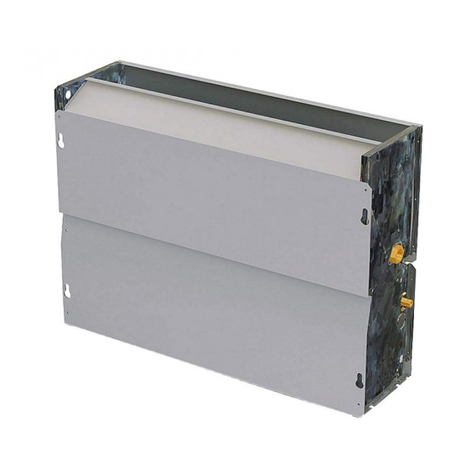
Kentatsu KFHC12H0EN1 User manual

Thank you very much for purchasing our fan coil unit,
Before using your unit, please read this manual carefully and keep it for future reference.
INSTALLATION&OPERATION MANUAL
FAN COIL UNITS
MODELS:
(R410A) KFHC12H0EN1
KFHC20H0EN1
KFHC25H0EN1
KFHC30H0EN1
KFHC38H0EN1
KFHC48H0EN1
KFHC57H0EN1
KFHC65H0EN1
KFHC78H0EN1
KFHE12H0EN1
KFHE20H0EN1
KFHE25H0EN1
KFHE30H0EN1
KFHE38H0EN1
KFHE48H0EN1
KFHE57H0EN1
KFHE65H0EN1
KFHE78H0EN1
DK14-03.01.27
1
CONTENT PAGE
I&O manual
PRECAUTION...........................................................................1
USER....................................................................................................2
INSTALLATION AND MAINTENANCE.......................................................6
DIMENSIONS...................................................................12
SPECIFICATION............................................................................14
Be sure to be in conformity with the local, national and
international laws and regulations.
Read "PRECAUTIONS" carefully before installation.
The following precautions include important safty items.
Observe them and never forget.
Keep this manual in a handy place for future reference.
Before out from factory, FAN COIL UNIT (AIR UNITS) has
passed Fan Coil Overpressure Resistant Test, Statically
and Dynamically Balanced Adjustment, Noise Test, Air
(cool) Volume Test, Electric Property Test, Outline Quality
Detection.
1. PRECAUTIONS
The safety precautions listed here are divided into two categories. In
either case, important safety information is listed which must be read
carefully.
WARNING
After completing the installation, make sure that the unit operates
properly during the start-up operation. Please instruct the customer
on how to operate the unit and keep it maintained.
Be sure only trained and qualified service personnel to
install, repair or service the equipment.
Improper installation, repair, and maintenance may result in
electric shocks, short-circuit, leaks, fire or other damage to
the equipment.
Failure to observe a warning may result in death.
Failure to observe a caution may result in injury or
damage to the equipment.
CAUTION
WARNING
Install according to this installation instructions strictly.
If installation is defective, it will cause water leakage,
electrical shock and fire.
When installing the unit in a small room, take measures
against to keep refrigerant concentration from exceeding
allowable safety limits in the event of refrigerant leakage.
Contact the place of purchase for more information.
Excessive refrigerant in a closed ambient can lead to oxygen
deficiency.
Use the attached accessories parts and specified parts
for installation.
otherwise, it will cause the set to fall, water leakage,
electrical shock and fire.
The appliance must be installed 2.3m above floor.
The appliance shall not be installed in the laundry.
Before obtaining access to terminals, all supply circuits
must be disconnected.
The appliance must be positioned so that the plug is
accessible.
The enclosure of the appliance shall be marked by word,
or by symbols, with the direction of the fluid flow.
For electrical work, follow the local national wiring
standard, regulation and this installation instructions. An
independent circuit and single outlet must be used.
If electrical circuit capacity is not enough or defect in
electrical work, it will cause electrical shock fire.
Use the specified cable and connect tightly and clamp
the cable so that no external force will be acted on the
terminal.
If connection or fixing is not perfect, it will cause heat-up or
fire at the connection.
Wiring routing must be properly arranged so that control
board cover is fixed properly.
If control board cover is not fixed perfectly, it will cause
heat-up at connection point of terminal, fire or electrical
shock.
If the supply cord is damaged, it must be replaced by the
manufacture or its service agent or a similarly qualified
person in order to avoid a hazard.
An all-pole disconnection switch having a contact
separation of at least 3mm in all poles should be
connected in fixed wiring.
When carrying out piping connection, take care not to let
air substances go into refrigeration cycle.
Otherwise, it will cause lower capacity, abnormal high
pressure in the refrigeration cycle.
Do not modify the length of the power supply cord or use
of extension cord, and do not share the single outlet with
other electrical appliances.
Otherwise, it will cause fire or electrical shock.
If the water leaks during installation, ventilate the area
immediately.
After completing the installation work, check that the
water does not leak.
The cool water in the unit is not lower than 3℃, hot water is
not higher than 65℃. Water in the unit must clean, air quality
must meet to the standard of PH=6.5~7.5.
2. USER
2
2.1 Machine description
The fan-coil unit for the threatment of air in indoor
environments,available in versions with casing,versions for
building-in.
2.1.1 Standard conditions of use
The fan-coil unit is intended for the treatment of air(summer and
winter climatisation)inside buildings used for domestic or similar
purposes.The unit is not designed for installation in roomsused
for laundry purposes.
CAUTION
DANGER!
The machines are designed for indoor installation for use in
domestic or similar environments.
DANGER!
Do not introduce objects through the air intate or delivery
grilles.
IMPORTANT!
The unit will function correctly only if the instructions for use
are scrupulously followed,if the specified clearances are
complied with during installation and if the operating
restrictions indicated in this manual are strictly adhered to.
IMPORTANT!
If clearance distances are not maintained at installation,it
could cause maintenance difficulties and reduction in
performance.
I&O manual
2.1.2 Construction features
1. Connections for standard coil;
2. Fixing slots;
3. Defrosting tray;
4. Condensate discharge;
5. Air filter;
6. Blower;
7. Coils;
Fig.2-1
DISPOSAL:Do not dispose this product as unsor-
ted municipal waste. Collection of such waste sepa-
rately for special treatment is necessary.
Ground the air conditioner.
Do not connect the ground wire to gas or water pipes,
lightning rod or a telephone ground wire.Incomplete
grounding may result in electric shocks.
Be sure to install an earth leakage breaker.
Failure to install an earth leakage breaker may result in
electric shocks.
Connect the outdoor unit wires , then connect the indoor
unit wires.
You are not allow to connect the air conditioner with the
power source until wiring and piping the air conditioner is
done.
While following the instructions in this installation
manual, install drain piping in order to ensure proper
drainage and insulate piping in order to prevent
condensation.
Improper drain piping may result in water leakage and
property damage.
Install the indoor and outdoor units, power supply wiring
and connecting wires at least 1 meter away from
televisions or radios in order to prevent image
interference or noise.
Depending on the radio waves, a distance of 1 meter may not
be sufficient enough to eliminate the noise.
This appliance is not intended for use by persons
(including children) with reduced physical,sensory or
mental capabilities, or lack of experience and knowledge,
unless they have been given supervision or instruction
concerning use of the appliance by a person responsible
for their safety.
Don't install the air conditioner in the following locations:
There is petrolatum existing.
There is salty air surrounding (near the coast).
There is caustic gas (the sulfide, for example) existing
in the air (near a hot spring).
The Volt vibrates violently (in the factories).
In buses or cabinets.
In kitchen where it is full of oil gas.
There is strong electromagnetic wave existing.
There are inflammable materials or gas.
There is acid or alkaline liquid evaporating.
Other special conditions.
CAUTION
2.1.3 Versions with casing
2.1.4 Built-in version II KFHE
Supply voltage 220-240V~ 1ph 50Hz;
Finned coil type heat-exchanger consisting of copper tubes and
aluminium fins,with connections on the left reversible to fit on
the right.
Three-speed centrifugal blower with aluminium blades statically
and dynamically babanced. Diretly-coupled motor equipped
with internal thermal protection and condenser permanently in
circuit.
Casing in pre-painted galvanised steel sheet,clad in a protective
film of PVC,complete with the-rmoacoustic insulation,grilles in
heat-resistant ABS polymer with fixed vanes.
Condensation collection tray with natural drainage,complete
with anti-condensation insulation.
Mesh filter in regenerable polypropylence.
VERSION II
VERSION I KFHC
Supply voltage 220-240V~ 1ph 50Hz;
Finned coil type heat-exchanger consisting of copper tubes and
aluminium fins,with connections on the left reversible to fit on
the right.
Three-speed centrifugal blower with aluminium blades statically
and dynamically babanced.
Diretly-coupled motor equipped with internal thermal protection
and condenser permanently in circuit.
Structure in galvanised sheet steel..
Condensation collection tray with natural drainage,complete
with anti-condensation insulation.
Mesh filter in regenerable polypropylence.
3
I&O manual
2.1.5 Restrictions on use
CAUTION
IMPORTANT!
The machine has been designed and built solely and
exclusively to function as a ceiling-mounted air-handling
terminal,supplied through ducting or panelling;any other use
is expressly prohibited.
Installation of the machine in an explosive environment is
also forbidden.
Fig.2-2
Fig.2-4
2.1.6 OPERATION RANGE
Use the system in the following temperature for safe and
effective operation.
Cooling operation
Heating operating
(cooling only
type without)
Mode
Temperature Outdoor
temperature Room
temperature water inlet
temperature
0°C~30°C
17°C~32°C
30°C~65°C
3°C~20°C
-15°C~24°C
0°C~43°C
NOTE
1
2
3
4
If air conditioner is used outside the above conditions, it
may cause the unit to function abnormally.
The phenomenon is normal that the surface of air
conditioning may condense water when the relative larger
humidity in room, please close the door and window.
Optimum performance will be achieved within these
operating temperature range.
Water system operating pressuer: Max: 1.6MPa, Min:
0.15MPa.
4
CAUTION
IMPORTANT!
Pay the utmost attention to the signs and symbols located on
the appliance.
CAUTION
IMPORTANT!
IMPORTANT!
In the case of a water supply with a particularly high content
of hard water salts,it is advisable to fit a water softener.
2.1.7 Information about further risks and unavoidable hazards
If any risks remain is spite of the provisions adopted,or if
there are any potential or hidden risks,there are indicated by
adhesive labels attached to the machine.
INSTALLATION PLACE INSTRUCTION
Controller installation place
(For suspending mounted, it is not allow to install the cabinet at here.)
According to the users' need,controller can be installed in left
side, right side or wall-fixed.
Thedetailsofinstallationmethodsaccordingtothe
installation manual for controller.
I&O manual
For safety, please shut off the power before maintenance.
Only use original spare parts and accessories.The company
shall not be held liable for damage caused by tampering or
work carried out by unauthorised personnel or malfunctions
caused by the use of non-original spare parts or accessories.
Start/stop the unit.
Select between the three blower speeds.
Thermostat adjustment and maintenance of the desired ambient
temperature.
Switching between operationg modes:cooling and heating.
Constant ventilation control.
Specific instructions for use are supplied with the controllers
themselves.
The following operations can be carried out using the control
panels:
2.1.8 Prolonged shutdown
CAUTION
IMPORTANT!
If the unit is not used during the winter period,the water
contained in the system may freeze.
If the machine is going to be out of use for long periods of
time,it is necessary to disconnect the unit from the mains by
opening the main switch (which is required to be fitted by the
installer).
If the unit is not used during the winter period,the water
contained in undertaken in good time.
Alternatively,a suitable quantity of anti-freeze should be
mixed with the water.
Cooling Heating
Fig.2-7
Fig.2-5
Fig.2-6
LOWMIDHIGHSH
black
blue
Fan motor
TV3a
3-way
valve
FAN COIL UNIT CONTROLLER
NL
POWER
blue
black
butted plug
butted plug
orange blue yellow
blue
brown
brown yellow white black red
2.3 Warnings and suggestions
2.2 Cleaning the unit
2.2.1 Cleaning the air filter
2.1.9 Startup after prolonged shutdown
CAUTION
DANGER!
Always switch off the electric power before beginning
cleaning or maintenance operations.
Do not spill water on the unit.
In versions with casing,it is possible to clean the outside of
the unit .For cleaning,use a soft cloth dampened with water
and alcohol. Do not use hot water,solvents or abrasives,or
corrosive substances.
Before starting up the unit again:
Clean or change the airfilters:
Clean the heat-exchanger.
Clean the condensation collector tray drain tube or make sure it
is clear.
Bleed any air from the water system.
It is advisable to run the unit at maximum speed for several
hours.
To ensure correct air intake,the air filter must be cleaned at
least once a month,or more frequently if the unit is being
used in very dusty environments.The filter must always be
removed from the unit for cleaning.
The filter is housed in the lower part of the unit in versions II
and III which take in air from below or from the rear.
To remove the filter in versions II and III proceed as following
indicated.
While it is housed in the front cowl in version I,which take in air from
the front.
To remove the filter in version I ,proceed as following indicated.
The air filter must be cleaned by blowing it out with compressed air
or washing it in water.Before refitting the filter,make sure it is clean
and completely dry.If the filter is damaged,it must be replaced with a
genuine corresponding filter.
Always avoid obstructing the flow of air,or using the unit as a
surface to lean on, The use of water or aerosol sprays in
proximity to the unit can cause electric shocks and
malfunctions.
5
I&O manual
3. INSTALLATION AND MAINTENANCE
3.1 TRANSPORT AND HANDLING
PACKAGING AND COMPONENTS
CAUTION
CAUTION
DANGER!
DO NOT OPEN OR TAMPER WITH THE PACKAGING
BEFORE INSTALLATION.
The units should only be moved and lifted by specialised
personnel trained in these operations.
Check on arrival that the unit has not been damaged during
transport and that it is complete with all its parts.
HANDLING INSTRUCTIONS
To remove the packaging ,follow these instructions:
Check for visible damage
Open the packaging.
Check that the packet containing the manual for use and
maintenance is insidel
Dispose of the packaging material in accordance with current
legislation,at the appropriate waste reception or recycling site.
1
2
3
4
PRESERVE THE ENVIRONMENT!
Dispose of the packaging materials in compliance
with the national or local legislation in force in your
country.
DANGER!
Do not leave the packagig within reach of children.
Fig.2-8
Fig.3-1
Fig.2-9
STORAGE CONDITIONS
CLEARANCES AND POSITIONING
CAUTION
IMPORTANT!
Incorrect positioning or installation of the unit may amplify
noise levels and vibrations generated during operation.
CAUTION
DANGER!
Movement of the unit should be performent with care,in order
to avoid damage to the external structure and to the internal
mechanical and electrical components.
Also make sure that there are no obstacles or people along
the route,to avoid the danger of collisions or crushing and to
prevent the lifting or handling device from turning over.
All the operations listed below must be carried out in
accordance with current health and safety regulations,both as
regards the equipment used and as regards the procedure
followed.Before commencing moving operations,check that
the lifting apparatus has the required capacity for the unit in
question.
The units may be moved or lifted either by hand or by means
of a suitable trolley.If the weight of the unit is more than 30
kg,moving units need to be moved at the same time,it is
advisable to put the machines in a container and lift them by
means of a crane or something similar.
Units in their packaging may be stacked not more than four
high,and must be kept under cover.
The units may be mounted vertically, provided that the
correct clearances for positioning are maintained.
Version
Version
6
I&O manual
Fig.3-2
Fig.3-4
≥20mm
≥a
≥a
≥a
≥a
≥
≥a
≥a
≥b
≥a
≥a
Version
amm
bmm
150 200
80
_
3.2 INSTALLATION
CAUTION
CAUTION
DANGER!
Installation must only be carried out by qualified
technicians,trained to work with air-conditioning and
refrigeration systems.Incorrect installation could lead to unit
malfunctioning and a consequent deterioration in
performance.
DANGER!
The unit must be installed according to national or local rules
in force at the time of installation.
For installation,follow the instructions set out below:
Remove the external casing(in versions I), unscrewing the
screws which secure it to the structure,as following indicated.
Mark out the fixing points on the wall or ceiling,either by marking
through the drillings in the unit itself,or by referring to the
measurements given in “7 DIMENSIONS”. Maintain a gentle fall
in the condensation drainage pipe, to ensrue that water escapes
properly.
3.2.1 HYDRAULIC CONNECTIONS
Connection to the system
Setting up the condensate drainage system
IMPORTANT!
It is most important that the hydraulic connections are made
with great care by specialised fitters.
IMPORTANT!
The water coils can be partially drained through the drain
valves.
To drain them completely,they should be blown out with an
air-jet.
CAUTION
Connect the unit to the water system by means of the fittings which
are marked Flow and Return.
All the water coils,including the optional extras,are equipped with air
bleed-valves next to the upper union,and with water drain valves
need to the lower union.
All the valves can be opened and closed with screwdrivers or
allenkeys.
Bleed the air contained in the circuit.
Lag the connection pipes and any valves titted with
anticondensation material 10 mm thick or install the auxiliary
drain.
Pour water into the condensation collector tray and check
that the liquid drains properly,following it right through to the
exit of the draintube.If it does not,check the fall and look for
possible blockages.
When installation is complete,it is necessary to :
The condensation drainage system must be set up with an
adequate fall,to ensure that the water escapes properly.
Following are directions for setting up a proper condensation
drainage system.
CAUTION
7
I&O manual
Table.3-1
Fig.3-7
Fig.3-6
Creation of the trap
Antifrost protection.
How to turn the coil round,from fittings on the left
(standard) to fittings on the right.
The condensation drainage system must be fitted with a
connect to the unit
condensate discharge
or defrosting tray.
suitable trap to prevent seepage of odours.Following are
directions for setting up the trap.
Aways provide a drainplug at the bottom of the trap,and
arrange it so that it can be quickly dismantled
CAUTION
CAUTION
IMPORTANT!
Position the drain-tube so that it does not put strain on the
drainage connector on the unit.
The unit is supplied as standard with connections to the coil on the
left.It is possible however to turn the coil round,so that the
connections are on the right.
The operation of turning the principal and supplementary coils round
can be carried out with the unit in situ,but it is preferable to do it
before installation,with the unit on solid ground.
Remove the casing(on versions I);
Remove the screws on both sides which hold the coil to the
structure of the unit;
Turn the coil round in the direction indicated in Fig;
Re-fit the coil mounting screws;
Re-fit the casing(on versions I)
Procedure to reverse the coil:
1
2
3
4
5
IMPORTANT!
When the unit is out of service,remember to arrange in good
time for the entire water content in the circuit to be drained
down.
IMPORTANT!
Mixing the water with glycol modifies the performance of the
unit.
Pay attention to the safety instructions regarding ethylene
glycol which are printed on the container.
If the unit is not used during the winter period,the water contained in
the system may freeze.
Draining the water circuit needs to be undertaken in good
time.However,if the operation of draining the systemis felt to be too
laborious,a suitable quantity of antifreeze may be mixed with the
water instead.
3.2.2 ELECTRICAL CONNECTIONS.
8
I&O manual
50mm 50mm
Fig.3-8
Fig.3-9
Fig.3-10
3 cm/m
CAUTION
IMPORTANT!
Electrical connection of the unit must be carried out by
qualified personnel in compliance with the regulations in
effect in the country where the unit is installed.The company
DANGER!
Always install a general automatic switch in a protected area
near the appliance with an adequate capacity characteristic
delayed curve with sufficient breaking power.There should be
a minimum distance of 3mm between the contacts. Earth
connection is compulsory by law to ensure user safety while
the machine is in use.
shall not be held liable for damage to persons or property
caused by incorrect electrical connection.
AIR FLOW(m3/h)
POWER
CIRCUIT BREAKER/FUSE(A)
PHASE
FREQUENCYAND VOLT
255~1530
1-phase
220-240V~ 50Hz
15/15
Table 5-2
an all-pole disconnection device which has at least 3mm
separation distance in all pole and a residual current
device(RCD)with the rating of above 10mA shall be incorpo-
rated in the fixed wiring according to the national rule.
The appliance shall be installed in accordance with national
wiring regulations.
WIRING
CAUTION
IMPORTANT!
Machine commissioning or the first start up must be carried
out by skilled personnel qualified to work on this type of
product.
DANGER!
Before starting up,make sure that the installation and
electrical connections have been carried out in accordance
with the instructions in this manual. Also make sure that there
are no unauthorised persons in the vicinity of the machine
during these operations.
3.2.3 STARTUP INSTRUCTIONS
9
I&O manual
Check that the voltage and the frequency of the electrical supply
correspond to 220-240V single phase at 50Hz;that the available
power is suffcient for the running the equipment; and that the
supply cables are of adequate section for the maximum current
which will be required.
Make sure that the electrical supply system complies with
current national safety regulations.
Electrical connections must be made in accordance with the
wiring diagrams supplied with the machine.For connection to the
electrical supply network,use double-insulated flexible
cable,twin pole + earth,section 1.5mm2,type H05RN-F.
Pass the supply cable through the slot beside the air filter.Use
the cable clamp provided on the inner side of the panel to
secure the supply cable and the connecting cables,and strip
only the length of cable needed to go into the connector block.
In the event that the unit is mounted on a metal surface,earth
connections must be made in compliance with local
regulations.If the optional extra electric heating element is
fitted,a separate power supply must be provided.Use double-
insulated flexible cable,twin pole + earth,section 2.5mm2,type
H05RN-F.
The installation of room and pipe temperature sensors
Outside temperature controller ( Fig.3-13)
Inside temperature controller ( Fig.3-12)
1. Install the room temperature sensor.
1) Dismount casing from equipment.
2) Fixing install the room temperature sensor (length: 600mm)
at air return orifice by cable clips and lead the sensor wire
through out the wire hole. (showed as the Fig.3-12)
3) Fix the room temperature sensor cable and connect it to
temperature controller.
1. Install the room temperature sensor
1) Connect the room temperature sensor (length: 150mm) to the
wire of temperature controller directly (Note: Pipe temperature
sensor be connected to the black wire of Temperature
controller, while Room temperature sensor be connected to
white wire of temperature controller. )
2. Install the pipe temperature sensor
1) Dismount casing from equipment.
2) Lead the pipe temperature sensor’s wire through out from
indoor unit and connecting to temperature controller via a long
connecting wire.
3) Mount up the casing.
Temperature controller (Wall-mounted)
Pipe temperature sensor
Room temperature
sensor(Length: 150mm)
Pipe temperature sensor’s
connected wire
Fig.3-11
Fig.3-13
T2
WHITE
WHITE
RED
BLACK
ORANGE
BLUE
INDOOR
FAN
CAP
YELLOW
Y/G
RED
BLACK
BROWN
YELLOW
WHITE
BLUE
TO CONTROLLER
TO POWER TO VALVE
XT1
LNSHHIG MID LOWTV3a
2. Install the pipe temperature sensor
1) Connect the pipe temperature sensor to the Temperature
Controller (Note: Pipe temperature sensor be connected to
the black wire of Temperature controller, while Room temperature
sensor be connected to white wire of temperature controller. )
2) Mount up the casing.
Pipe temperature sensor
Room temperature sensor
(Length: 600mm)
Fig.3-12
( Which together with room temperature
sensor’s wire goes out from
the same side in the unit.)
3.2.4 MAINTENANCE
PRELIMINARY CHECKS BEFORE STARTUP
Pipeline system has been vacuumed before initial start the
equipment (see Fig.3-14)
the unit is positioned correctly;
the flow and return pipes of the water system are correctly
connected;
the pipes are clean and free of air;
the unit falls correctly towards the drainage outlet and the
trap;
the heat-exchangers are clean;
the electrical connections are correct;
the screws holding the cables are well tightened;
the supply voltage is as required;
the power consumption of the blower is correct and does not
exceed the maximum permitted.
Before starting up the unit,make sure that:
1 Remove the connecting pipe’s side cover panel by cross
screwdriver.
2 Remove the bolts that showed at the figure by slotted screw
driver. Start up the pump to circulate the pipeline water and
vacuum air from the system until there have water flow out
from bolt holes, and then tighten the boltsthe system.
3 Shutdown the sestem that showed at the figure by slotted
screwed and replace the side cover panel.
10
I&O manual
Fig.3-14
SCHEDULED MAINTENANCE
Once a month
Check the state of cleanliness of the air filters.
The air filters are made of fibre and are washable in
water.The state of cleanliness of the filters must be
checked regularly at the start of the operating season and
on a monthly basis.
Every six months
Check the state of cleanliness of the heat-exchanger and
the condensation drain-tube. With the unit switched
off,remove the casing of the machine and check the state
of the heat-exchanger and the condensation drain-tube.If
necessary:
At the end of the season
Drain the water system(for all heat exchangers).
Electrical Circuit
The following operations are recommended for the
maintenance of the electrical circuit:
remove any foreign bodies from the finned surface
which may obstruct air flow;
clean off the dust with a jet of compressed air;
wash and brush,gently,with water;
dry with a jet of compressed air;
check that there are no obstructions in the
condensation drain tube which could prevent the
normal flow of water.
1
2
4
3
remove the casing of the machine (on units I );
start the system and run for a few minutes;
stop the system;
slacken the bleed screw on the inlet manifold and
bleed the air.
Repeat the operation several times until no more air
comes out of the system.
1
2
check the unit 's power absorption using a clip-on
ammeter and compare the reading with the values
shown on the documentation;
inspect and,if necessary, tighten the electrical
contacts and terminals.
1
2
5
3
4
Remove the casing (on units I )
Disconnect the electrical supply cable from the
blower;
Remove the screws on both sides which hold the
blower to the structure of the unit;
Take out the blower.
1
2
3
4
Check for the presence of air in the water system.
To avoid the risk of rupture due to freezing, it is
advisable to drain the water from the system atthe
end of every season.
NON-SCHEDULED MAINTENANCE
Replacement of the blower assembly
In the case of burnout of the blower electric
motor,it is necessary to replace the entire blower
assembly.
Procedure for removal of the blower:
CAUTION
DANGER!
Maintenance work must only be carried out by qualified
technicians authorised to work on air-conditioning and
refrigeration systems. Use suitable work gloves.
Do not introduce pointed objects through the air intake grilles.
Always disconnect the unit from the mains power supply at
the main isolator switch before carrying out maintenance
work or checks.Make sure that no one accidentally supplies
power to the machine, lock the main switch in the Off
position.
Disconnect the power supply before cleaning and maintenance.
Use dry cloth to clean the unit.
Remove the casing(on units I );
Isolate the flow and return water pipes;
Disconnect the coil from the water system;
Remove the screws on both sides which hold the
coil to the structure of the unit;
Take out the heat-exchanger coil.
1
2
3
4
5
Replacement of the heat-exchanger coil
Procedure for removal of the heat-exchanger:
5 Procedure for refitting the blower is a reversal of the
above.
11
I&O manual
DISMANTLING THE UNIT AND DISPOSAL OF
HARMFUL SUBSTANCES
Procedure for refitting the heat-exchanger is a
reversal of the above.
6
PRESERVE THE ENVIRONMENT!
We care about protecting the environment. When the unit is
dismantled it is important to adhere scrupulously to the following
procedures.
The unit should only be dismantled by a firm authorized
for the disposal of scrap machinery.
The unit as a whole is composed of materials considered
as secondary raw materials and the following conditions
must be observed:
If the system has antifreeze as an additive,it must not be
just dumped,because it causes pollution.It should be
collected and suitably disposed of.
The electronic components(electrolytic condensers)
should be considered special waste,and as such they
should be delivered to a firm authorised to collect them.
The expanded polyurethane rubber insulation on the
pipes and the expanded polyethylene mesh,the xpanded
polyurethane and sound-absorbent spong lining the
bodywork must be removed and processed as urban
refuse.
1
2
3
Fig.3-15
Fig.3-16
4. DIMENSIONS
4.1 VERSION I KFHC
VERSION I 786557483830252012
A(mm) 1500150015001200120010001000800800
B(mm) 128412841284984984784784584584
C(mm) 120012001200900900700700500500
D(mm) 122612261226926926726726526526
626
626
115
345
203291
115
258
74
220
143
A
B
220
150
D
105
185
207
46
140
55
150
12
I&O manual
Fig.4-1
Fig.4-4
Fig.4-5
Fig.4-3
Table.4-1
13
I&O manual
4.2 VERSION II KFHE
VERSION
A(mm) 125012 50125095095075075 0550550
B(mm) 122612 26122692692672672 6526526
C(mm) 120012 00120090090070070 0500500
D(mm) 123212 32123293293273273 2532532
212
A
D
545
46 105
126
345
203
291
185
258
B
A
C
212
87
Fig.4-6
Fig.4-7
Fig.4-8
Fig.4-9
Table.4-2
12 20 25 30 38 48 57 65 78
14
I&O manual
MODEL 786557483830252012
Cooling
capacity(W)(*)
Heating
capacity(W)(**)
Air volume
(m3/h)
Sound pressure
(dB(A))(***)
Rated input
(W)
Rated current
(A)
Weight(kg)
Weight
(kg)
Blowers
(n )
Height of feet
(mm)
Standard coil
connections
Condensation drain
pipe connection
220-240V~ 1ph 50Hz
Power supply
16mm
/ G(M)
34
80 80 80 80 80 80 80 80 80
11222 2333
1150 1870 2530 3270 3970 4850 5640 6520 7850
2530 3490 4580 5640 6980 8230 9580 11690
425 510 680 765 850 1020 1360 1530
35 37 39 41 43 44 46 48
22.5 26 26 32.5 32.5 39 39 39
17 20 20 25 25
Water flow
rate(L/h)(*) 323 435 562 683 835 969 1122 1349
Water side pressure
drops(kPa)(*) 10.1 14.2 9.5 10.3 24.6 11.4 9.5 12.1
16.5 9.3 13.5 8.6 20.8 10.1 9.5 11.7
Water flow
rate(L/H)(**) 364 492 631 774 899 1071 1343 1589
Water side pressure
drops(kPa)(**) 9.5
197
18.3
1520
222
255
32
22.5
17
(*)In the following conditions:ambient temperature 27 C D.B.;19 C W.B.;temperature of inlet water 7C with
t5C;at highspeed.
(**)In the followingconditions:ambient temperature20C;temperatureof inlet water70C with t10 C;at high
speed.
(***)Sound pressure level in dB(A)refers toameasurement takenat adistance of 1m from the point of exit
of the air,with the outlet open.
5. SPECIFICATION
VERSION I II
I
II
I
II
27
29
29
30
40
44
46
44
35
36
49
51
63
64
88
95
137
143
0.12
0.13
0.14
0.15
0.19
0.19
0.2
0.19
0.15
0.157
0.22
0.23
0.27
0.28
0.38
0.41
0.61
0.64
32 32 32
Table.5-1

This manual suits for next models

17

Other Kentatsu Air Conditioner manuals

Kentatsu KFHD12H0EN1 Operating manual

Kentatsu

Kentatsu KFHD12H0EN1 Operating manual

Kentatsu KSGRE/KSRRE26HZAN1 User manual

Kentatsu

Kentatsu KSGRE/KSRRE26HZAN1 User manual

Kentatsu KRFN220CFAN3 User manual

Kentatsu

Kentatsu KRFN220CFAN3 User manual

Kentatsu KSTU440HFAN1 User manual

Kentatsu

Kentatsu KSTU440HFAN1 User manual

Popular Air Conditioner manuals by other brands

LG AS-W096 series owner's manual

LG

LG AS-W096 series owner's manual

Haier ESA3067 - annexe 1 user manual

Haier

Haier ESA3067 - annexe 1 user manual

Hitachi RAS-10C9K instruction manual

Hitachi

Hitachi RAS-10C9K instruction manual

Haier SUPER MATCH AS12NS1HRA-GOLDEN Service manual

Haier

Haier SUPER MATCH AS12NS1HRA-GOLDEN Service manual

Carrier MODULINE 37HS Application data

Carrier

Carrier MODULINE 37HS Application data

Technibel PHRIE 095 installation instructions

Technibel

Technibel PHRIE 095 installation instructions

Mitsubishi Electric Mr. Slim MXZ-2B20NA Service manual

Mitsubishi Electric

Mitsubishi Electric Mr. Slim MXZ-2B20NA Service manual

Daikin FTXM41VVLT Operation manual

Daikin

Daikin FTXM41VVLT Operation manual

Panasonic CS-E7LKEW Service manual

Panasonic

Panasonic CS-E7LKEW Service manual

Kolin KLM-IF70-3D3M user manual

Kolin

Kolin KLM-IF70-3D3M user manual

Fujitsu AOU 9RLFW Service instructions

Fujitsu

Fujitsu AOU 9RLFW Service instructions

Toshiba RAS-B10UFV installation manual

Toshiba

Toshiba RAS-B10UFV installation manual

Carrier 40GRQ owner's manual

Carrier

Carrier 40GRQ owner's manual

Carrier 50HJ008-014 Installation, Start-Up and Service Instructions

Carrier

Carrier 50HJ008-014 Installation, Start-Up and Service Instructions

York TCGD12 S21S2H Technical guide

York

York TCGD12 S21S2H Technical guide

INVENTOR CLCO290-09BS user manual

INVENTOR

INVENTOR CLCO290-09BS user manual

Sanyo XS2422 Service manual

Sanyo

Sanyo XS2422 Service manual

Haier AW094AAMAA Operation manual

Haier

Haier AW094AAMAA Operation manual

manuals.online logo
manuals.online logoBrands
  • About & Mission
  • Contact us
  • Privacy Policy
  • Terms and Conditions

Copyright 2025 Manuals.Online. All Rights Reserved.