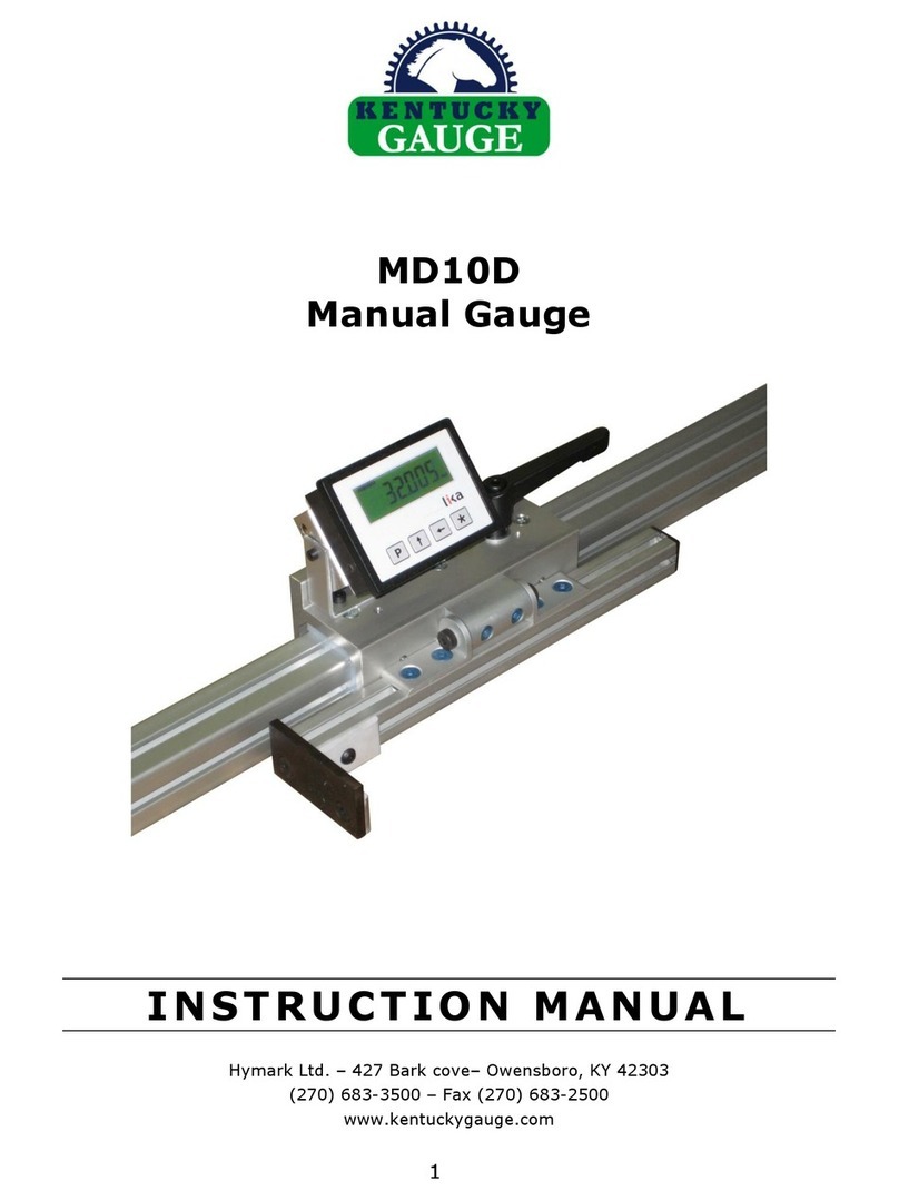
Kentucky MMP User manual

1
MMP
Digital Length Measuring Gauge
*shown with optional measuring surface
I NS TR U CT IO N M A NU AL
Hymark Ltd. –427 Bark cove–Owensboro, KY 42303
(270) 683-3500 –Fax (270) 683-2500
www.kentuckygauge.com

2

3
Table of contents
1. Product Description 4
1.1 Intended use 4
2. Basic Safety Hints 5
2.1 Notice hints inside manual 5
2.2 Owner obligations 5
2.3 Operator obligations 5
2.4 Intended use 5
3. Maintenance Requirements 7
3.1 Lubricants and Detergents 7
3.2 Maintenance Schedule 7
3.3 Cleaning the Guide Rail 7
3.4 Cleaning the Magnetic Tape 7
3.5 Cleaning the Carriage 8
3.6 Cleaning the Contact Plates 8
4. DRO Operation 9
4.1 Setting the Datum 9
4.2 Entering/Changing the Datum Value 9
4.3 Setting the Display Mode (Inch-to-metric) 9
4.4 Changing from Absolute to Incremental Measuring 9
5. DRO Parameter Mode 10
5.1 Entering Parameter Mode 10
5.2 Editing Paramters 10
5.3 How to exit Paramter Mode 10
5.4 Parameter List 10
6. DRO Specs 13
6.1 Dimensional Drawing 13
6.2 Technical Data 13
6.3 Integrated Sensor Specs 13
7. Warranty 14

4
1. Product Description
1.1 Intended Use
The only acceptable use for the MMP is as a length measuring gauge system. Never place
any material on the measuring surface except the piece to be measured. Any other use is
not intended and is a misuse of the gauging system.
Contact
Plates
Optional Measuring
Surface
Digital
Readout
Guide
Rail
Carriage

5
2. Basic safety hints
2.1 Read and follow all hints inside the Instruction Manual
Basic requirements for the correct use of the gauging system or the machine are the
knowledge of the basic safety hints and the safety precautions.
This instruction manual contains the most important safety hints.
This instruction manual, especially the safety hints and precautions must be followed by
every person working with this gauge or machine.
Also follow all general plant safety rules and precautions not mentioned in this manual.
2.2 Owner obligations
The owner agrees to only allow the gauge or the machine to be used by qualified and trained
persons who
-Have been instructed in the general safety rules and precautions
-Have been instructed in the correct use of the gauge and machine
-Have read and understood the safety chapters and caution hints of this instruction
manual.
2.3 Operator obligations
All persons working with this gauge and machine agree before starting to work
-To follow the general safety rules
-To read and understand the safety chapters and caution hints of this instruction manual.
2.4 Intended use
The only acceptable use for this gauge is as a length gauging system. Any other use is not
intended and is a misuse of the gauging system.
Hymark is not liable for any damages resulting from misuse.
Intended use also means:
-Following all safety hints and precautions mentioned in this manual
-Following the maintenance and inspection procedures as mentioned
in this manual.

6
Note: LCD displays is powered by 1 ‘C’ battery and will not power off.
Battery will need to be replaced approximately every 12 months.
Contact
Plates
Optional Measuring
Surface
Digital
Readout
Guide
Rail
Carriage

7
3Maintenance Requirements
Maintenance jobs as described in this chapter may only be done by authorized and trained
personnel.
**Prior to any maintenance of the Kentucky Gauge or accessories, please ensure the
machine is not in operation and corresponding equipment is in “off” position.
3.1 Lubricants and Detergents
Detergent
Use commercially available detergents.
Don’t use any acids or alkaline solutions
Don’t use any high pressure water jet cleaners
3.2 Maintenance Schedule
See
chapter
Device
Cleaning
Lubricate
In addition
Frequency
3.3
Guide Rail
X
--
--
daily
3.4
Magnetic tape mounted to
bottom side of aluminum
extrusion
X
--
--
daily
3.5
Carriage
X
--
--
daily
3.6
Contact Plates
X
X
--
daily
Legend: X - has to be done -- Nothing to do
3.3 Cleaning the Guide Rail
Remove chips, grease and any items on the conveyor/table that would be
deemed in the pathway of, or causing an unwanted obstruction of, the
carriage/gang stop. This should be done several times per day if the machine
is in heavy use.
3.4 Cleaning the Magnetic Tape
Remove chips and grease on the magnetic tape and between reader head and
tape. This should be checked daily to ensure there is no development of debris
or obstruction. If heavy chip or debris accumulation occurs, increase frequency
to accommodate suitable maintenance measures.
The sensor to scale gap should be within the range of 0.1mm to 1.0mm

8
3.5 Cleaning the carriage
Remove chips, grease and any items on the conveyor/table/measuring surface
that would be deemed in the pathway of, or causing an unwanted obstruction
of, the carriage/contact plate. This should be done several times per day if the
machine is in heavy use.
Ensure that the hardware connecting the contact plates to the carriage is
secured. This may be checked on a quarterly basis or implemented in line with
the standard preventative maitneance schedules for the other equipment in
the facility.
3.6 Cleaning the contact plates
Wipe down plates and remove any dirt, grime, or moisture.
Apply a liberal coat of oil (3-n-1 oil or similar) to every exposed surface of the
contact plates to prevent corrosion.

9
4 DRO Operation
P: Program (programming/change parameters)
: UP (increase value of selected digit)
: Shift left (select digit)
*: Save (save data)
4.1 Setting Datum (Referencing the system)
By setting the datum or referencing the system, the operator is setting up the system so
that the distance from the moving contact plate to the stationary contact plate is correctly
displayed in the digital readout.
NOTE: Your datum value needs to be set before performing this function.
See “4.2 Entering / changing datum value”
1. Move the stop to a known location using a standard or other suitable method.
2. Press the *button for 3 seconds.
3. The display will show “rESEt”
4. Press the * button again to show the current position flashing. Note: at this point the
referencing can be cancelled by pressing “P”
5. Press the * button again to confirm the reference reset by displaying “done”
momentarily. This will set the display to the pre-entered datum value.
4.2 Entering / changing datum value
Push Pand buttons together to display datum value “rEF’. Use and keys to change
value and save with *button.
This feature is only enabled if “F_rEF” parameter is set to “on” (see chapter 5).
4.3 Setting the Display Mode (Toggle from inch to metric)
The display can be easily changed to display inch or metric values by pressing the button
for 3 seconds. Note: inch mode with 3 decimals or fraction display must be selected in
parameter Inch_F (see chapter 5).
4.4 Changing from Absolute Measuring to Incremental Measuring
The display can be changed from absolute measuring (unit displays actual distance from saw
blade) to incremental or relative measuring (unit displays distance from last position).
Pressing the Pand *buttons together toggles these modes.
Note: INC is shown in the display when the unit is running in incremental mode.
Note: Setting the display to zero in incremental mode is not affecting the real absolute value

10
5. DRO Parameter Mode
5.1 Entering Parameter Mode
Press Pbutton for 3 seconds to enter setup mode. “SEtUP” will be shown in the display.
Press button to enter Menu 1 (parameter mode)
5.2 Editing Parameters
Press Pbutton to select next Parameter and Parameter setting.
Press *button to save entered values
5.3 How to exit Parameter Mode
Press Pbutton until you reach final parameter rESEt.
Now press Pbutton twice to return to operating mode.
5.4 Parameter List
Parameter description Factory Setting User Setting
dG_Ln Degrees/Linear (dG, dG2, Lin) Lin __________
Angular or linear display mode.
Lin = ..0,0..0,1..0,2..0,3 mm
dG1 = angles
..–0,1°..0,0°..+0,1°..+359,9°..0,0°
dG2= angles
..359,9°..0,0°..0,1°..359,9°..0,0°
*= save, P = next parameter
Note: when selecting dG1 or dG2 the next
available parameter will be FrEE not rES.
rES Resolution (10, 50, 100, 1000, FrEE) 10 __________
Linear resolution value in microns.
10 = 0.01mm
50 = 0.05 mm
100 = 0.1 mm
1000 = 1 mm
FrEE allows to enter a resolution factor e.g.
for angular displays (basis of calculation is
max. resolution 0.01 mm).
*= save, P = next parameter
FrEE Ln mode (0,0001, 1,0000) - __________
FrEE dG mode (0,0001, 9,9999)
e.g. angle display with range from 0° to 90°
and 0,1° resolution on a rotating table with
circumference of 785,4 mm. Total working
range is 785,4 mm : 4 = 196.35 mm.
FrEE = 900 : 19635 = 0,045836
*= save, P = next parameter

11
Parameter description Factory Setting User Setting
Measurement unit (both, dEc, Inch) both __________
Sets the display mode.
both = mm/inch can be selected
(see chapter 4.6)
<jump to parameters dd_n, Inch_F>
dEc = mm display mode
<jump to parameter dd_n>
Inch = inch display mode
<jump to parameter Inch_F>
*= save, P = next parameter
dd_n Decimal digit number (0, 1, 2) - __________
Sets the decimal point position.
0 = no decimal point
1 = one decimal (e.g. 1,0)
2 = two decimals (e.g. 1,00)
*= save, P = next parameter
Inch_F Inch function (Inch1, Inch2) Inch2 __________
Sets the inch display mode.
Inch1 = inch with 3 decimals (e.g. 1234.567)
Inch2 = fraction mode (e.g. 12.31.64 = 12" 31/64)
*= save, P = next parameter
dIr Counting direction (uP, dn) uP __________
uP = up (standard direction)
dn = down (inverted direction)
*= save, P = next parameter
F_rEL Incremental mode activation (on, oFF) on __________
Enables incremental mode by pushing P and *
buttons together
on = activated
oFF = deactivated
*= save, P = next parameter
F_rSt Datuming mode (on, oFF) on __________
Enables datum function by pushing *button
on = activated
oFF = deactivated
*= save, P = next parameter
F_rEF Datum modification function (on, oFF) on __________
Enables “change reference value” mode by
pushing P and buttons together
on = activated
oFF = deactivated
*= save, P = next parameter

12
Parameter description Factory Setting User Setting
F_oFS Offset mode (on, oFF) oFF __________
Enables offset modification function by
pushing P and buttons together
on = activated
oFF = deactivated
*= save, P = next parameter
rEF Datum value (-999999, 999999) 0 __________
Absolute reference value for encoder.
This value is displayed by pushing the
* button for 3 seconds.
Note: displayed value = actual value +
offset values (if entered).
*= save, P = next parameter
OFSt1 Offset1 value (-999999, 999999) 0 __________
First offset value (e.g. tool offset). This value
Will be added to actual value
*= save, P = next parameter
OFSt2 Offset2 value (-999999, 999999) 0 __________
Second Offset value. This value will be added
to actual value + OFSt1.
*= save, P = next parameter
OFSt3 Offset3 value (-999999, 999999) 0 __________
Third Offset value. This value will be added
to actual value + OFST1 + OFST2.
*= save, P = next parameter
rESEt
Press Pbutton to reset display and exit menu.
Display will show rEF+OFSt1 value.
Push Pbutton again to exit Setup mode and
to return to operating mode

13
6. DRO Specs
6.1 DRO Dimensional Drawing (mm)
6.2 Technical Data
LCD display : 7 digits plus sign symbol , 11 mm high
Battery : 1 commonly available “C” battery , 1.5V
Consumption : 700 μA
Operating temperature : -20°C to 80°C (-4°F to 176°F)
Operating Speed : max. 2.5m/sec (100in/sec)
Resolution : 0.001in
Housing : Black metal for panel mounting
Dimensions (mm) : 96w x 73h x 47d
Cut Out (mm) : 91.5w x 67.5h
Protection Class : IP60 front, IP40 back
6.3 Integrated Sensor Specifications
Technical Data
Cable Length : 0.2 m
Protection : IP67
Operating Temperature : 5°C - 50°C (41°F-122°F)
Orientation : Any
Bend Radius : min 60mm (2.5in)
Gap Tape/Sensor : max 1mm (0.04in)

14
9 Warranty
Hymark Ltd Co (henceforth Hymark), warrants this product for a period of twenty-four (24)
months from the date of shipment. During the warranty period, under authorized return
component parts to Hymark freight prepaid, the company will repair, or at its option, replace
any part found to be defective in material or workmanship, without charge to the owner for
parts, service labor, or associated customary shipping costs.
This same protection will extend to any subsequent owner during the warranty period. It
does not apply to damage caused by accident, misuse, fire, flood or acts of God, or from
failure to properly install, operate, or maintain the product in accordance with the printed
instructions provided.
Any questions or inquiries should be directed to our factory technical department at 270-
683-3500 ext. 114
Hymark Ltd. –427 Bark cove–Owensboro, KY 42303
(270) 683-3500 –Fax (270) 683-2500
www.kentuckygauge.com
This warranty is in lieu of any other warranties, expressed or implied, including
merchantability or fitness for a particular purpose, which are expressly included.
The owner agrees that Hymark´s liability with respect to this product shall be set
forth in this warranty, and incidental or consequential damages are expressly
excluded.

LD14x
User anual
LD140-M7 + SM25
LD141-M7-R-…
LD142-M7-R-…
Description
This manual describes the LD14x battery display
series and the sensors o the SM25 series. The
purpose o this system is to display linear or angular
displacements on industrial machines and on
automation systems. The measurement system
includes a battery powered LCD display, magnetic
tape and a magnetic sensor. As the sensor is moved
along the magnetic tape, it detects the displacement
which is shown on the display. The lexibility o the
tape allows it to be used or both linear and angular
applications.
Chapters
1 Sa ety summary
2 Identi ication
3 Installation
4 Mounting recommendations
5 Electrical connections
6 Setup
7 RS232 serial inter ace (only with option I1)
8 Dimensional drawings and cut-out
1 - Safety su ary
We strongly recommend care ully reading this user
manual and ollowing the installation guidelines:
•Sensor head should be installed as close as
possible to the display.
•Avoid running the sensor cable near high
voltage power cables (e.g. drive cables).
•Avoid mounting sensor head near capacitive or
inductive noise sources such as relays, motors,
and switching power supplies.
Connect according to chapter 5.
2 - Identification
The display and sensor can be identi ied by the
label's data (ordering code, serial number). This
in ormation is listed in the delivery document. For
technical eatures please re er to the product
catalogue.
3 - Installation
Install the product according to the protection level
provided.
Protect the system against knocks, riction, solvents,
temperatures under –0°C (32°F) and over +60°C
(+140°F).
Be sure that the system is mounted where hard or
sharp objects (e.g. metal chips) do not come into
contact with the magnetic scale and the bottom o
the sensor head. I these conditions cannot be
avoided provide a wiper or pressurized air.
4 - Mounting reco endations
4.1 Display
Push the display into the cut-out without panel
clips.
Install panel clips on the display's housing and screw
until ixed and stable.
Power supply by 1.5V commercial battery type C (or
AM2 / BABY / LR14 / MN1400 / SP/HP11).
4.2 Magnetic tape
See manual supplied with the magnetic tape.
4.3 Sensor ounting
4.3.1 Sensor SM25-R (rectangular)
Sensor can be ixed by means o two M3 screws
over the buttonholes. Make sure that the gap
between sensor and tape is in respect with ( ig. 1)
along the total measuring length. Avoid contact
between the parts. You can check planarity and
parallelism between sensor and magnetic tape using
a eeler gauge.
____________________________________________________________________________________________
MAN LD14x I_E_D 4.3 9 www.lika.it
www.lika.biz

LD14x
D
<1°
<3°
<3°
igure 1
D = 0,1 mm - 1,0 mm
4.3.2 Sensor SM25-C (circular)
The sensor can be ixed in a corresponding
mounting hole by means o the two nuts. Make sure
that the gap between sensor and tape is in respect
with ( ig. 2) along the total measuring length.
Observe the correct align ent of the arker on
the tape. Avoid contact between the parts. You can
check planarity and parallelism between sensor and
magnetic tape using a eeler gauge.
<3°
DMarker
igure 2
D = 0,1 mm - 1,0 mm
5 - Electrical connections
5.1 SM25 sensor (only LD140)
Plug in the sensor's Mini-DIN connector (circular) on
backside o the display.
5.2 RS232 serial interface (only with option I1)
Connect PC to LD14x with NULL MODEM
COMPUTER AT CROSS OVER cable (9 pin emale - 9
pin emale) available in commerce.
Electrical cable connection:
Pin PC Function Pin LD14x
1
2 Rx 3
3 Tx 2
4 DTR 6 *
5 GND 5
6 DSR
7 RTS 8 *
8 CTS
9
* Power supply has to be provided to RS232
inter ace to avoid battery consummation. I not
connect to the PC provide power supply (8-15Vdc)
to pin 6 or 8. External supply isn’t needed i using a
Modem computer cable!
____________________________________________________________________________________________
MAN LD14x I_E_D 4.3 10 www.lika.it
www.lika.biz

LD14x
6 - Setup
6.1 Key's function
: UP (select value)
: Shi t links (select digit)
* : Save (save data)
P : Program (programming/change parameter)
6.2 Key co binations / Quick functions
6.2.1 Set datu (reference)
Push * key or 3 sec. to access reset unction
(“rESEt” will be displayed).
Push P key to exit unction (no reset).
Push * key twice to con irm datum value (“donE”
will be displayed).
Display value = rEF + OFS1 + OFSx (where OFSx is
the actually set O set value).
This unction is enabled only i “F_rSt” parameter is
set “yES”.
6.2.2 Incre ental easure ent
Push P and * key simultaneously to switch rom
absolute measurement to incremental.
Zero setting in incremental modes (see 6.2.1) does
not change absolute value in the background.
The unction is enabled only i "F_rEL" parameter is
set "yES".
6.2.3 M /inch display odes
Mm/inch display modus can be changed by pushing
key or 3 s. The unction is enabled only i
"F_ I" parameter is set "yES".
6.2.4 Offset value odification
Push P and keys simultaneously to display 1.
O set value (OFS1). Use and keys to change
value and save with * key. Further O set values
OFS2 and OFS3 can be changed only in setup menu.
O set unction is enable i “F_oFS” parameter is set
“yES”.
key allows to scroll OFS1, OFS2 and OFS3 values.
OFS1 = actual value + OFS1 + rEF
OFS2 = actual value + OFS1 + OFS2 + rEF
OFS3 = actual value + OFS1 + OFS3 + rEF
6.2.4.1 Fractional offset display
The ractional inch display mode allows to set o set
values (OFS) in the ollowing way:
- 1st digit blinking → increases 1/64” pushing key.
- 2nd digit blinking → increases 1/32” pushing key.
- 3rd digit blinking → increases 1/16” pushing key.
- 4th digit blinking → increases 1/8” pushing key.
- 5th digit blinking → increases 1” pushing key.
- 6th digit blinking → increases 10” pushing key.
6.2.5 Datu odification
Push simultaneously P and keys to display datum
value rEF. Use and keys to change value and
save with * key.
This unction is enabled only i “F_rEF” parameter is
set “yES”.
6.3 Setup / Para eter setting
Push P key or 3 s to enter setup and “SEtUP” is
displayed.
Push key to enter MENU 1 (parameters)
Push * key to enter MENU 2 (RS232 serial
inter ace)
Push P key to access the next Parameter and
Parameter setting.
Push P key or 3 s to exit the setup at any point.
6.3.1 Default para eters (factory settings)
All de ault values are written in BOLD characters.
The display can be reset to de ault parameters with
the ollowing procedure:
•take out battery and wait or 10 s.
•while putting in the battery push * key
(“dEFPar” is displayed)
---------------------------------------------------
6.3.2 Para eter list MENUE 1
Unit Measurement unit [dEC, FrEE, dG1, dG2, IdEC, I rct]
Sets the measurement unit and the display mode.
dEC = linear measurement display (decimal)
FrEE = display with conversion actor
dG1 = angular display (-∞..-0,1°..0,0°..+0,1°..+∞)
dG2 = angular display (..359,9°..0,0°..359,9°..0,0°..)
IdEC = inch display mode
I rct = ractional inch mode (eg. 12.31.64 = 12" 31/64)
* = save, P = next parameter, P or 3 s. = exit
____________________________________________________________________________________________
MAN LD14x I_E_D 4.3 11 www.lika.it
www.lika.biz

LD14x
COn only with Unit = FrEE, dG1, dG2
Allows to set a ree conversion actor to display
non-metric units or angles.
Valeu range:
FrEE = 0,00001 - 1,00000
dG1, dG2 = 0,00001 - 9,99999
Exa ple 1:
Want to display a 90° angle ( rom 0° to 90°) with
0,1° resolution on a round table with 785,4 mm
circum erence.
The measurement length on 360° is 785,4 mm,
though on 90.0° it is 785,4 / 4 = 196.35.
COn = 900 : 19635 = 0,045836
Exa ple 2:
Want to display angles on a magnetic ring with
diameter 114,5 mm.
The circum erence is 114.5 * 3.14 = 359.53 mm
COn = 3600 : 35953 = 0,10013
* = save, P = next parameter, P or 3 s. = exit
rES Resolution
(only with Unit = dEC, FrEE, dG1, dG2, IdEC )
Sets the resolution to be displayed.
Unit = dEC, FrEE, dG1, dG2 = 0.001, 0.005, 0.01, 0.05, 0.1, 0.5, 1
Unit = IdEC = 0.0001, 0.0005, 0.001, 0.005, 0.01, 0.05, 0.1
* = save, P = next parameter, P or 3 s. = exit
dIr Counting direction [uP, dn]
uP = up (standard direction)
dn = down (inverted direction)
* = save, P = next parameter, P or 3 s. = exit
---------------------------------------------------
6.3.3 Additional function of MENUE 1
F_ I mm/inch unction [yES, no]
Enables the mm/inch unction (by pushing key)
yES = enabled
no = disabled
* = save, P = next parameter, P or 3 s. = exit
F_rEL Incremental measurement unction [yES, no]
Enables incremental measurement unction (by
pushing P and * keys).
yES = enabled
no = disabled
* = save, P = next parameter, P or 3 s. = exit
F_rSt Datum unction [yES, no]
Enables datum unction (by pushing * key).
yES = enabled
no = disabled
* = save, P = next parameter, P or 3 s. = exit
F_rEF Datum modi ication unction [yES, no]
Enables re erence modi ication unction (by pushing
P and key).
yES = enabled
no = disabled
* = save, P = next parameter, P or 3 s. = exit
F_oFS O set modi ication unction [yES, no]
Enables o set modi ication unction (by pushing P
and keys).
yES = enabled
no = disabled
* = save, P = next parameter, P or 3 s. = exit
rEF Datum value [-999999, 999999]
Absolute re erence value or the measuring system.
This value is displayed by pushing * key or 3 s.
(displayed value includes previously set o set
values).
* = save, P = next parameter, P or 3 s. = exit
OFS1 O set1 value [-999999, 999999]
First o set value (e.g. tool correction). This value is
added to actual value (see 6.2.3.)
* = save, P = next parameter, P or 3 s. = exit
____________________________________________________________________________________________
MAN LD14x I_E_D 4.3 12 www.lika.it
www.lika.biz

LD14x
OFS2 O set2 value [-999999, 999999]
Second O set value. This value is added to actual
value and OFS1.
* = save, P = next parameter, P or 3 s. = exit
OFS3 O set3 value [-999999, 999999]
Third O set value. This value is added to actual
value, OFS1 and OFS2.
* = save, P = next parameter, P or 3 s. = exit
When the setup is completed the display shows
"rESEt"
Push * key twice to reset the display and quit the
setup. "donE" will be displayed.
Push P key quit the setup without resetting the
display. "no rSt" will be displayed.
---------------------------------------------
6.3.4 Para eter list MENUE 2
Ad xx Device address [01, 31]
Setting o device address (only i ordered with serial
inter ace (option I1).
For setting use and keys.
* = save, P = next parameter
H_cntr Hour meter (1/10 h)
Elapsed time indication (display connected to
battery). Resolution is 1/10 hour (6 minutes).
* = save, P = next parameter
7 - RS232 serial interface (option I1)
I the display is provided with RS232 serial inter ace,
the ollowing commands can be used.
7.1 RS232 para eters
9600 Baud, 8Bit, no Parity, 1 Stop bit, Xon/Xo
7.2 Serial co ands
Serial commands must have the ollowing structure:
| A D C M N D = X
where:
|: PC keyboard symbol
AD: device address (00 to 31) 2 digit
CMND: command (see command list)
X: value range (see command list)
Upon receipt o a wrong command the display will
answer with the same command + ? and checksum
(e.g. sent command: |02azs → answer |02azs?EF)
Any common terminal program can be used or
communication with LD140 (e.g. Hyperterminal).
Commands will be send a ter con irmation by ENTER
key (carriage return).
Answers are structured as ollows:
ADCMND:SXXXXXXXXCK
where:
AD: device address
CMND: command
XXXXXXXX: value
CHKS: checksum
The checksum is equal to the least signi icant byte
o the summing the hex values o all characters
transmitted.
Exa ple:
The displayed position is 8,29. The position o device
with address 01 is read by means o the |01TPOS
command.
The answer is: 01TPOS:+000008299F
The sum o hex values o all characters is the
ollowing:
30+31+54+50+4F+53+3A+2B+30+30+30+30+30+
38+32+39 = 39F
The least signi icant byte o 39F is 9F which is the
checksum.
____________________________________________________________________________________________
MAN LD14x I_E_D 4.3 13 www.lika.it
www.lika.biz

LD14x
7.2.1 Co and list
(below the device address is indicated with AD)
Zeroing of device address
|00RSET
Address o all connected devices is set to zero (0).
Device address [1, 31]
|00INIT=X
Sets address o all connected devices to value X.
Display device address
|00DADR
Displays device address until P key is pushed.
Change device address [1, 31]
|ADRADR=X
Changes actual device address AD to X.
Answer : ADTADR:+XCHKS (CHKS is checksum and X
is value).
Read actual position
|ADTPOS
Reads actual position o device AD (resolution o
value is 0,01mm or 0,001 inch depending on
settings).
Change counting direction [0, 1]
|ADRDIR=X
Sets counting direction.
X=0 → uP = standard direction
X=1→ dn = inverted direction
Answer: ADTDIR:+0000000XCHKS
Read counting direction
|ADTDIR
Reads the actual counting direction.
X=0→uP , X=1→dn
Answer: ADTDIR:+0000000XCHKS
Measure ent unit [0, 5]
|ADRUNI=X
Sets the measurement unit and display mode.
X=0→ dEC = decimal mode
X=1→ FrEE = display with conversion actor
X=2→ dG1 = angular (-∞..-0,1°..0,0°..+0,1°..+∞)
X=3→ dG2 = angular (..359,9°..0,0°..359,9°..0,0°..)
X=4→ IdEc = decimal inch display mode
X=5→ I rct = ractional (es. 12.31.64 = 12" 31/64)
Answer: ADTUNI:+0000000XCHKS
Read easure ent unit
|ADTUNI
Reads the status o measurement unit.
Answer: ADTUNI:+0000000XCHKS
Resolution [1, 5, 10, 50, 100, 500, 1000]
|ADRRES=X
Sets linear resolution in mm or
inch
.
X=1→ 0.001/
0.0001
, X=5→ 0.005/
0.0005
,
X=10→ 0.01/
0.001
, X=50→ 0.05/
0.005
,
X=100→ 0.1/
0.01
, X=500→ 0.5/
0.05
,
X=1000→ 1/
0.1
Answer: ADTRES:+XCHKS
Read resolution
|ADTRES
Reads value o actual resolution (see values above).
Answer: ADTRES:+XCHKS
Free conversion factor COn
[with FrEE 0,00001 - 1,00000 / with dG1, dG2 0,00001 - 9,99999]
|ADRFRE=X
Sets ree conversion actor COn (see chapter 6.3.1).
Answer: ADTFCO:+XCHKS
Read COn conversion factor
|ADTFCO
Reads value o actual COn actor.
Answer: ADTFCO:+00X.XXXXCHKS
Display /inch display ode [0, 1]
|ADRMMI=X
Changes display mode rom mm to inch.
X=0→ mm, X=1→inch
Answer: ADTMMI:+0000000XCHKS
____________________________________________________________________________________________
MAN LD14x I_E_D 4.3 14 www.lika.it
www.lika.biz
Table of contents
Other Kentucky Measuring Instrument manuals