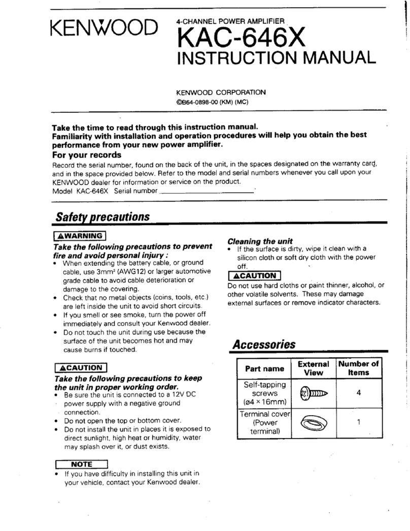
Kenwood KAC-887 User manual

ss)
ae
ee
a
i
5
W
i)
ise
det
gee
}
CCE
T
EE
ALLO
L
TCO
TTL
tNTSte
itt
SO
eeeinetnenemeentensnantretnhbanbeninventoutnersienmemeroeninntem
=
2
&s
|
"XS
“oO
x
B
.
rT<
:
|
|
i
:
ch
it
ict
=
31-4010-0
Slide
s
4
MAIN
AMPLIFIER
Q
xe)
=
5
©
89
oS
&
Ws
|
to
i
90-05
D
~{
AOR
PR
rEX.
socket
head
bolt
)
i
Z
<
i
:
3
>
O5
—O
5O
:
rd
0
a
cord
21
x
r
1
é
0620
rs
k.
kK
Heat
FO
4
Spea
E30
Spea
E30
(
06
Speaker
cord
(E30-0622-05
®
apes
©
~
o
%
amet
ive)
{

DISASSEMBLY
FOR
REPAIR
DISASSEMBLY
Remove
the
metallic
cabinet
and
bottom
plate
to
enable
replacement
of
resistors,
capacitors
and
transistors.
Remove
the
lead
holder
and
rear
panel
before
replacing
ICs.
It
is
not
always
necessary
to
remove
the
lead
holder
and
rear
panel,
if
a
flexible
screwdriver
is
available.
)
If
both
ICs
on
one
heat
sink
block
are
defective,
unsolder
all
the
IC
pins
and
remove
the
screws
holding
the
heat
sink
to
the
PC
board.
(2)
Pull
out
the
ICs
and
the
heat
sink
from
the
PC
board
and
replace
them
with
new
ones.
If
one
of
the
ICs
on
a
heat
sink
block
is
defective,
remove
the
black
heat
sink.
©)
Heat
sink
Black
heat
sink
@
O®
Remove
screws
holding
the
small
heat
sink
to
the
PC
board.
Incline
the
heat
sink
in
the
direction
indicated
by
the
arrow
(5),
remove
the
screws
holding
the
IC
to
the
heat
sink
and
replace
it.
Unsolder
the
terminals
to
replace
the
capacitor
assembly
or
the
choke
coil.
Capacitor
Ass’y

Lila
DISASSEMBLY
FOR
REPAIR
/
CIRCUIT
DESCRIPTION
CHECKING
PROCEDURE
Connect
the
GND
pattern
of
the
input
circuit
and
the
body
of
sensitivity
switch
to
that
of
the
output
circuit
or
the
chassis
of
the
capacitor
assembly,
then
connect
terminal
3
of
the
DIN
cord
to
the
power
source
before
checking
voltages.
CAPACITOR
ASS'Y
|
(
x
GND
Fig.
2
CIRCUIT
DESCRIPTION
1.
Power
ON/OFF
circuit
No
power
switch
is
provided
on
the
exterior
of
the
KAC-887.
Instead,
a
relay
and
transistors
(Q5
and
Q6)
are
used
to
turn
the
power
ON
and
OFF.
The
voltage
supplied
through
ter-
minal
3
of
the
DIN
cord
is
used
to
control
Q5
and
Q6.
When
voltage
is
supplied,
Q5
and
O6
are
turned
ON
to
actuate
the
RED
)
)F
csp
)
Soy
D3)
eee
+
CO
2B:
\
Sees!
Ppa
(
oa
BATTERY
13.8V
relay
so
that
the
power
is
fed
to
the
power
27
dlifier
circuit.
When
it
is
turned
OFF,
the
relay
is
releases
=~
the
power
-
amplifier
is
turned
OFF.

CIRCUIT
DESCRIPTION
2.
pPC
1230H
This
IC
is
designed
so
that
the
IC
and
speaker
are
protected
against
shorts
which
may
occur
between
the
output
terminal
and
ground
when
the
IC
is
used
in
the
BTL-OCL
connection.
NON-INVERTING
INPUT
(12)
GND
(OUTPUT)
(8)
RIPPLE
FILTER
Q)
+B
(0)
BOOT
STRAP
1
(1)
OUTPUT
1
i
>
ou
<
O
Z
=
[om
ee)
>
<
(7)
GND
(INPUT)
©
N
=
~
a
E
a
.o)
2
THERMAL
PROTECTOR
SURGE
|
Ly
ef
|
©
ee
TT
aia
:
—
|
Bee
| |
Q3!
Fig.
4
SCHEMATIC
OF
pPC
1230H
INTERNAL

‘5
CIRCUIT
DESCRIPTION
;
3.
ISOLATION
AMPLIFIER
@
1h
+
a
R21
O.
=
INPUT
9
-
Ol,
Sl,
LLL
LLL
O
INPUT
CIRCUIT
GND
O+B
O
OUTPUT
&
OUTPUT
CIRCUIT
GND
Fig.
5
ISOLATION
AMPLIFIER
Each
car
audio
component
is
generally
grounded
to
an
appropriate
point
on
the
car
body.
Therefore,
equipment
connected
to
the
power
amplifier
may
have
a
grounding
point
different
from
that
of
the
power
amplifier.
If
there
is
a
potential
difference
between
the
grounding
points,
it
will
be
reproduc-
ed
as
a
noise
in
the
speakers.
In
the
KAC-887,
the
input
Circuit
ground
is
isolated
from
that
of
the
power
amplifier
cir-
cuit
by
using
an
isolation
amplifier
so
that
noise
is
reduced.
Transistors
Q1
and
Q7
in
Figure
5
operate
as
an
inverting
amplifier
and
a
ripple
filter,
respectively,
when
there
is
no
potential
difference
between
the
ground
of
the
input
circuit
®
and
that
of
the
power
amplifier
®).
This
is
because
the
circuit
iS
equivalent
to
the
circuit
in
which
@
and
®)are
connected.
Assume
that
an
AC
noise
source,
Ey
is
connected
between
®
and
(8)
as
shown
in
Figure
6.
The
impedance
of
C63
is
negligible
when
an
AC
signal
is
dealt
with;
therefore,
Ey
is
applied
to
the
base
of
Q7
with
its
phase
and
amplitude
unchanged
and
is
added
to
the
DC
voltage
(V-)
at
the
emitter
of
Q7.
Thus,
the
base
voltage
of
Q1
is
given
by
R21
(Vet+En)
+R1
7Ey
R21V¢_
Ve
=
R21+R17..——~SO
RT
RTD
Ot
Oe
t
DC
voltage
Noise
This
indicates
that
Ey
is
applied
to
the
base
of
Q1.
Or
the
other
hand,
Ew
is
applied
to
the
connection
between
R25
and
R29
since
the
impedance
of
C5
is
negligible.
Therefore.
the
voltage
level
at
both
the
base
and
emitter
vary
according
7D
En
and
there
is
no
change
in
potential
difference
betweer
the
two.
Thus,
Ey
is
not
output
from
the
collector
of
Q1.
R21
Fig.
6

PC
BOARD
POWER
AMPLIFIER
(X07-1920-10)
Foil
side
view
Note:
O
19)
®
i
ev)
®)
{
ee
ot
Refer
to
the
schematic
diagram
for
the
values
of
resistors
and
capacitors.
The
PC
board
drawing
is
viewed
from
the
side
easy
to
check.
t
‘wena?

LR
nn
re
gg
a
te
et
4
MAIN
AMPLIFIER
|
ae
aRRcrerIa
He
CAUTION
=~
This
amplifier
uses
the
BTL
connected
circuit
as
mentioned
before,
so
|
make
sure
of
the
following.
Since
the
ground
line
of
the
amplifier
is
floated,
when
connecting
the
measuring
instruments
(oscilloscope,
VIVM,
distortion
meter,
load
resistors
etc.),
make
sure
to
use
the
”
QKENWOOD'
A
B
Cc
:
DB)
q
floated
GND
terminals.
When
their
grounds
are
connected
to
the
ground
terminals
of
the
power
supply,
oscillator,
etc.,
the
output
of
(X07
=I9
ak)
a
—_————
eee
ee
ne
i
eee
the
zPC
1230H
will
be
short-circuited
and
IC
may
be
damaged.
[
!
L_
_
—“
x
!
REAR
a
aan
a
ge
|
ie
i]
ar
©
BLK
2
a.
aro
1
=
Y
XC
GND
t
:
HIGH
<=
LOW
—
R2
lo
R10
33K
R'I8
33K
CAPACITOR
ASS’Y
|
i
‘ie
ee
;
10
BLU
V
I3V
1.3V
OV
OV.
13.6V
13.8V
128.
€7V.
OV
[
0)
Y
v
Tmt
)H
seat
5
6
7
8
9
ev
4
i
|
|
:
he
L_
GRY
|
Hs
=D)
|
REAR
OUTPUT
:
Os
da
|
t-
|
Rch
GRY
Y
(CTD
(-)
|
ook
MOLD
(-)
|
Rech
J
ORG
9s
oe
|
’
FRONT
OUTPUT
GRY
Ho
ac
A
GRN
m=
ay
Ri2
33K
Prt
Ea
©
DI
8
RED
;
A
OOO
Lif
+8
(+13.8Vv)
ree
31
IOA
A
=.
dl
=
820P
Hi00
I6v
©
.
UPCI230H
>
2SA1175(H,F,E,
K)
-
28C2785
(H,
F,E,
K)
INPUT
>
25C1735(0,E)
>
UO5B
.
>
WO6B
.
1$1555
or
IS2076
KAC
—
887(k)
©
2801735
2SA1175
BPO
t230h
Bees
DC
voltages
are
measured
by
a
VOM
with
20
kQ/V
input
impedance.
-
2$SC2785
Fea.
B
e
E
8
SPECIFICATIONS
Total
Output
Power
..............
60
W
Power
per
Channel...............
15
W
into
4
9,
Input
Sensitivity
20~
30,000
Hz,
1%
THD
Total
Harmonic
Distortion
......
0.05%
(at
1
kHz,
4
watts)
Frequency
Response
............
20~
50,000
Hz
(+3
dB)
Signal
to
Noise
Ratio.............
92
dB
(A-weighted)
Sire
te
ihe
See
ete
22
mV/110
mV
1
W
Output
Input
Impedance..................
15
kQ/5
kQ
Load
Impedance
Power
Source
Bice
Saitek
1.3
kg
(2.9
Ib)
Semiconductor
Substitutions
Substitutions
2SA1175
2SA733,
2SA999
2S5C2003
2SC945,
2$C2320
«=
28C1735
2SC2785
na
een
eee
42
(4~8
Q
Allowable)
ees
Fete
Fiat
yet
en
14.4
V
(11~16
V
Allowable)
outa,
142x53x158
mm
7
‘

>
at
FL
ESD
28
RPO
RR
OC
CRO
n
Oe
Om
2
|
4
a
KAG-887
EXPLODED
VIEW
M2.6
x6
y
(F)
BLK
M2.6x6
(F)
BLK
1
M3
x6
‘
(Br-Tap)
M3
x6
M3x6
(8r-Tap)
Q)
M3
x6
(Br-Tap)
:(Br-Tap
)
3
(Br-Tap)
M3xl2
BLK
>
N30-30t2-
45
M2.6x6
(m—
(Br
-Tap)
M3x6
(Br-Tap)
BLK
:
N87-3006-45
M3x6
(8r-
Tap)
:
N8&7-3006-46
M3x
10(B8r-Tap)
:
N87-3010-46
M2.6x6(F-Tap)BLK
:
N88-2606-45
KAC-887
KAG-887
KAG-887
+
:
New
parts.
Parts
without
Parts
No.
are
not
supplied.
Les
articles
non
mentionnés
dans
le
Parts
No.
ne
sont
pas
fournis.
Teile
ohne
Parts
No.
werden
nicht
geliefert.
Ref.
No.
Parts
No.
ee
Bat
#8
KAC-887
3
Description
BOTTOM
PLATE
BLIND
SHEET
HOLDER
A01-0411-03
A23=-1941-04
METALLIC
CABINET
REAR
PANEL
B46-0055=30
B46-0063-13
B46-0063=13
846-0070=-03
B46-0070=03
WARRANTY
CARD
WARRANTY
CARD
WARRANTY
CARD
WARRANTY
CARO
WARRANTY
CARD
B46-0070-03
B46-0077-04
B50-3386-00
B50-3386-00
B50-3387-00
WARRANTY
CARD
WARRANTY
CARD
INSTRUCTION
MANUAL
INSTRUCTION
MANUAL
INSTRUCTION
MANUAL
B50-3387-00
850-3387=00
B50=-3387-00
INSTRUCTION
MANUAL
INSTRUCTION
MANUAL
INSTRUCTION
MANUAL
C91-0195-05
|
CAPACITOR
ASSY
E30-0619-05
E30-0620-05
E30-0621-05
E30-0622-05
SPEAKER
CORD
(BLU/GRY)
SPEAKER
CORD
(RED/GRY)
SPEAKER
CORD
(GRN/GRY)
SPEAKER
CORD
(ORG/GRY)
GND
CORD
E30-0633-45
E30-0686=05
DIN
CODE
OC
CODE
F01=-0383=03
F01-0384=03
F95-1031-05
HEAT
SINK
(CL)
HEAT
SINK
(CR)
FUSE
250V
10A
H01#3309=-04
H10-1584-02
H12-0084=08
H25-0029=04
H25-0067=03
CARTON
BOX
POLYSTYRENE
FIXTURE
PACKING
FIXTURE
BAG
BAG
H25-0112-04
H25=0173=04
BAG
BAG
J2123029=04
MOUNTING
HAROWARE
N99-0054205
N09=0390=05
SCREW
NUT
SET
HEX.SOCKET
HEAD
BOLT
X07=1920-10
|
POWER
AMP
PCB
ASSY
POWER
AMP
(X07-1920-10)
C24=21410-61
|
ELECTRO
10uUF
25wy
C24-1247-61
|
ELECTRO
47UF
16WV
C24"1722°59
|
ELECTRO
2,2UF
SOWV
C5221782-16
|
CERAMIC
820PF
K
C2401010"79
|
ELECTRO
100UF
10wWwV
C24+1210"79
|
ELECTRO
100UF
16WV
C24=1233=71
|
ELECTRO
330UF
16WV
C45-1710946
|
MYLAR
O.1UF
M
C25=-1710"57
|ELECTRO
1UF
SOwV
C24=21047-69
|
ELECTRO
47UF
10WV
C2401247"71
|
ELECTRO
470UF
16WV
C90"0564"05
|
ELECTRO
15000UF
16WV
C25-171075S7
|
ELECTRO
1UF
SOWV
C2421247-61
|
ELECTRO
47uUF
16WV
C45-1722-26
|
MYLAR
0.0022UF
Mm
K:
U.S.A.
U:
PX
P:
Canada
-
AAFES
E:
Europe
M:
Other
area
H:
Audio
club
=X:
Australia
PARTS
LIST
Parts
No.
Description
Bm
ASR
C71-1727-06
|
CERAMIC
27PF
L15=0023-05
|
CHOKE
COIL
$51-1032-05
|
RELAY
;
$31-4010-05
|
SLIDE
SWITCH
V11=0270-05
|
U05B
V11-0295-05
|
wO6B
V11-0271-05
|
1§2076
OR
181555
V30-0620-10
|
UPC1230H
V01=1175-30
|
2SA117S5
(Hp
FZE,K)
VO03—-2785-20
|
2502785
(H,F,E)
V03=0452-05
|
25¢1735(D-E)
V03=2785-20
|
25C2785(H,FeE)
V01-1175-30
|
28A1175(HDF,E,K)
Raa
ae
Re
a
ca
A
product
of
TRIO-KENWOOD
CORPORATION
Shionogi
Shibuya
Building,
17-5,
2-chome
Shibuya,
Shibuya-ku,
Tokyo
150
Japan
ar
a
ae
KENWOOD
ELECTRONICS,
INC.
1315
E
Watsoncenter
Rd.
Carson,
California
90745,
U.S.A.
75
Seaview
Drive,
Secaucus,
New
Jersey
07094,
U.S.A.
1098
North
Tower
Lane,
Bensenville,
Illinois
60106,
U.S.A.
TRIO-KENWOOD
CANADA
INC.
1070
Jayson
Court
Mississauga,
Ontario
Canada
L4W
2V5
TRIO-KENWOOD
ELECTRONICS,
N.V.
Leuvensesteenweg
504,
B-1930
Zaventem,
Belgium
TRIO-KENWOOD
ELECTRONICS,
GmbH
Rudolf-Braas-Str.
20,
6056
Heusenstamm,
West
Germany
TRIO-KENWOOD
FRANCE
S.A.
5,
Boulevard
Ney,
75018
Paris,
France
TRIO-KENWOOD
SVENSKA
AB
Kemistvagen
10A,
183-21
Taby,
Sweden
TRIO-KENWOOD
AG
Unterboesch
6331
Huenenberg/ZUG
Switzerland
TRIO-KENWOOD
(AUSTRALIA)
PTY.
LTD.
30
Whiting
St.,
Artarmon,
N.S.W.
2064,
Australia
KENWOOD
&
LEE
ELECTRONICS,
LTD.
Wang
Kee
Building,
5th
Floor,
34-37,
Connaught
Road
Central,
Hong
Kong
©
1981-5
PRINTED
IN
JAPAN
B51-1213-00
(T)
2313
Table of contents
Other Kenwood Amplifier manuals

Kenwood
Kenwood KAC-728S User manual

Kenwood
Kenwood KM-991 User manual

Kenwood
Kenwood BASIC M1D User manual

Kenwood
Kenwood KAC-M3004 User manual

Kenwood
Kenwood KAF-S500 User manual

Kenwood
Kenwood KAC-8406 User manual

Kenwood
Kenwood R-K1000 User manual

Kenwood
Kenwood KA-V7500 User manual

Kenwood
Kenwood KTC-1000R User manual

Kenwood
Kenwood KA-995 User manual

Kenwood
Kenwood KA-892 User manual

Kenwood
Kenwood KM-895 User manual

Kenwood
Kenwood KA-501 User manual

Kenwood
Kenwood Basic M1A User manual

Kenwood
Kenwood KAC-M615D User manual

Kenwood
Kenwood KAC-6405 User manual

Kenwood
Kenwood KAC-644 User manual

Kenwood
Kenwood KA-996 User manual

Kenwood
Kenwood KA-36 User manual

Kenwood
Kenwood A-58 User manual