Belden GRASS VALLEY HDA-3911 Instruction Manual

HDA-3911/-3931
Single/Dual 3G-HD-SD SDI Distribution Amplifiers
Guide to Installation and Operation
M3056-9900-100
2015-08-21

GUIDE TO INSTALLATION AND OPERATION
HDA-3911/31
Electromagnetic Compatibility
This equipment has been tested for verification of compliance with FCC Part 15, Subpart B requirements for
Class A digital devices.
NOTE: This equipment has been tested and found to comply with the limits for a Class A digital device, pursuant to
part 15 of the FCC Rules. These limits are designed to provide reasonable protection against harmful interference
when the equipment is operated in a commercial environment. This equipment generates, uses, and can radiate
radio frequency energy and, if not installed and used in accordance with the instruction manual, may cause harmful
interference to radio communications. Operation of this equipment in a residential area is likely to cause harmful
interference in which case the user will be required to correct the interference at his own expense.
This equipment has been tested and found to comply with the requirements of the EMC directive
2004/108/CE:
•EN 55022 Class A radiated and conducted emissions
•ENV 50204 Radiated EMF Immunity – RF 900 MHz Pulsed
•EN 61000-3-2 Harmonic current emission limits
•EN 61000-3-3 Voltage fluctuations and flicker limitations
•EN 61000-4-2 Electrostatic discharge immunity
•EN 61000-4-3 Radiated electromagnetic field immunity – radio frequencies
•EN 61000-4-4 Electrical fast transient immunity
•EN 61000-4-5 Surge transient immunity
•EN 61000-4-11 Voltage-dips, short-interruption and voltage variation immunity

GUIDE TO INSTALLATION AND OPERATION
HDA-3911/31
Table of Contents
1HDA Single/Dual 3 Gbps HD-SDI Distribution Amplifiers......................................................1
1.1 Introduction ......................................................................................................................................... 1
1.2 Features.............................................................................................................................................. 1
1.3 Block Diagrams................................................................................................................................... 1
1.4 Front Card-edge Interface................................................................................................................... 2
2Installation................................................................................................................................3
2.1 Installation of Rear Connector Panels ................................................................................................ 3
2.2 Card Installation.................................................................................................................................. 4
2.3 Rear Connector Panels....................................................................................................................... 4
2.4 Bypass Relay...................................................................................................................................... 6
3Operation..................................................................................................................................7
3.1 Control Options................................................................................................................................... 7
3.2 Card-Edge Status LED ....................................................................................................................... 7
3.3 Local control using the Densité 3 frame control panel........................................................................ 8
3.3.1 Overview................................................................................................................................ 8
3.3.2 Menu for local control............................................................................................................. 8
3.4 Remote control using iControl............................................................................................................. 9
3.4.1 The iControl graphic interface window................................................................................... 9
3.4.2 The Input panel.................................................................................................................... 11
3.4.3 The Rear panel .................................................................................................................... 12
3.4.4 The Status panel.................................................................................................................. 12
3.4.5 The Output panel ................................................................................................................. 13
3.4.6 The Alarms panel................................................................................................................. 13
3.4.7 The Info panel...................................................................................................................... 16
3.4.8 The Presets panel................................................................................................................ 17
4Specifications.........................................................................................................................18
5Contact Us..............................................................................................................................19
Grass Valley Technical Support................................................................................................................. 19
Corporate Head Office............................................................................................................................... 19
ANNEX 1 – HDA-3911/3931 Local User Interface.......................................................................20
ANNEX 2 – Installing the Optical Interface.................................................................................22

GUIDE TO INSTALLATION AND OPERATION
HDA-3911/31

GUIDE TO INSTALLATION AND OPERATION
HDA-3911/31 | 1
1 HDA-3911/3931 Single/Dual 3G-HD-SD SDI Distribution Amplifiers
1.1 Introduction
The HDA-3911/3931 is a 3G-HD-SD SDI video Distribution Amplifier supporting a variety of compressed and
uncompressed serial digital video signals. The HDA-3911/3931 provides 9 reclocked outputs with automatic
equalization for up to 140 meters of cable (Belden 1694A) at 1.485 Gbps and up to 90 meters at 2.97 Gbps. The
HDA-3931 also offers the added benefit of implementing a dual 1x4 amplifier instead of a single 1x9.
When longer cable lengths are required, the HDA-3911/3931 are ideal since they can natively offer fiber connectivity.
Additional protection for critical applications is provided by an optional protection bypass relay available on selected
rears.
The HDA-3911/3931 will also support DVB-ASI on selected outputs.
1.2 Features
•One (HDA-3911) or two (HDA-3931) inputs
•Up to nine 3GHD-SD SDI outputs
•Supports bit-rates all the way up to 2.97 Gbps
•Maximum flexibility offered by HDA-3931 with two operation modes: single and dual within Densité-3
•Automatic format detection and cable equalization
•Optional fiber I/O
•Optional bypass relay protection
•DVB-ASI format is also supported (not on all outputs – see rear panel drawings in Fig. 2.1 for details)
1.3 Block Diagrams
Figure 1.1(a) HDA-3911 Functional Block Diagram

GUIDE TO INSTALLATION AND OPERATION
2| HDA-3911/31
Figure 1.1(b)HDA-3931 Functional Block Diagram
1.4 Front Card-edge Interface
The front card-edge of the HDA-3911/31 incorporates two
elements:
•Status LED (see section 3.2)
•Select Button (see section 3.3)
Select Button
IRD-3802
Status LED
Status
Select
HDA-3911
Figure 1.2
Front card-edge layout

GUIDE TO INSTALLATION AND OPERATION
HDA-3911/31 | 3
2 Installation
2.1 Installation of Rear Connector Panels
The HDA-3911/31 card is sized to fit into Grass Valley’s Densité 3 frame. Grass Valley Densité-series cards are each
associated with a rear connector panel, which must be installed in the Densité 3 frame before the card can be
inserted.
The following rear connector panels are available:
For the HDA-3911:
•HDA-391N-3SRP Single rear for 1x7 operating mode.
•HDA-391N-3SRP-R Single rear for 1x7 operating mode with bypass protection relay.
•HDA-391N-3SRP-F Single rear for 1x5 operating mode with fiber option support.
For the HDA-3931:
•HDA-393N-3SRP Single rear for dual 1x3 operating mode.
•HDA-393N-3SRP-F Single rear for dual 1x3 operating mode with fiber option support.
•HDA-393N-3DRP Double rear for dual 1x4 operating mode.
All cards and rear panels can be installed with the frame power on. The card has connectors which plug into a mid-
frame mother board for distribution of power and for connection to the controller card, and a second connector which
plugs directly into the rear connector panel for input and output.
The rear connector panel must be installed with the card out of the frame.
•To remove an existing card from the slot, tilt up the swivel handle on the front of the card to lever the connectors
apart, then use the handle to pull the card straight out of the slot.
Densité 3 frame – rear panel installation

GUIDE TO INSTALLATION AND OPERATION
4| HDA-3911/31
To install the connector panel:
1. If a card is installed in the slot whose rear panel is being changed, remove it as described above.
2. Remove the existing panel (either blank or belonging to an existing card that is being changed) by releasing the
captive screw(s) at the bottom.
3. Position the new panel and secure it in place with the captive screw(s) at the bottom.
2.2 Card Installation
Once a matching rear connector panel has been installed, install the HDA-39x1 card as follows:
1. Open the front panel of the frame.
2. Slide the HDA-39x1 card into the slot and push gently on the handle to seat the connectors.
If the card is used with a double-width rear panel (3DRP), it should be inserted into the right-hand slot. Inserting
the card into the wrong slot will not damage the card, and will be flagged by the on-card status LED flashing red
to indicate that there is no connection to the rear panel.
3. Close the front panel of the frame.
2.3 Rear Connector Panels
The following diagrams illustrate the layout and connectors on the available HDA-3911 and HDA-3931 rear panels.
HDA-3911 Rear Panels:
•HDA-391N-3SRP Single rear for 1x7 operating mode.
•HDA-391N-3SRP-RSingle rear for 1x7 operating mode with bypass protection relay.
•HDA-391N-3SRP-F Single rear for 1x5 operating mode with fiber option support.

GUIDE TO INSTALLATION AND OPERATION
HDA-3911/31 | 5
HDA-3931 Rear Panels:
•HDA-393N-3SRP Single rear for dual 1x3 operating mode.
•
•HDA-393N-3SRP-F Single rear for dual 1x3 operating mode with fiber option support.
•HDA-393N-3DRP Double rear for dual 1x4 operating mode.
This table summarizes the input/output connections on the various rear panels shown above:
I/O Connections Use with
Rear panel type 3G-HD-SD
SDI IN 3G-HD-SD
SDI OUT FIBER I/O Bypass HDA-3911 HDA-3931
HDA-391N-3SRP 1 7
HDA-391N-3SRP-R 1 7
HDA-391N-3SRP-F 1 5
HDA-393N-3SRP 2 2 x 3
HDA-393N-3SRP-F * 2 2 x 3
HDA-393N-3DRP 2 2 x 4
* Note that the HDA-393N-3SRP-F panel uses DIN1.0/2.3 connectors on outputs A2/A3 and B2/B3. All other
electrical connectors on all panels are BNC.
NOTE - The outputs labeled with white letters on a black circle DO NOT support ASI output

GUIDE TO INSTALLATION AND OPERATION
6| HDA-3911/31
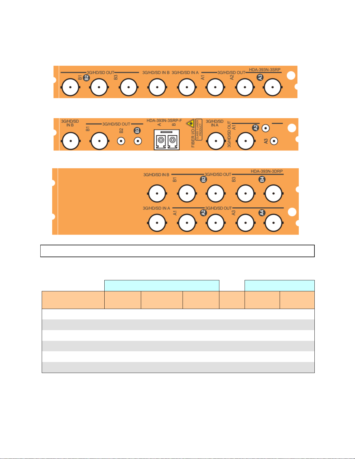
3G-HD-SD IN – serial digital video inputs
Connect a serial digital video signal, conforming to the SMPTE 424M for 3 Gbps input signals, the SMPTE 292M
standard for HD input signals or SMPTE 259M standard for SD input signals, to the BNC labeled 3G-HD-SD IN. DVB-
ASI is also supported. The HDA-39x1 will automatically switch to the detected video line format.
3G-HDSD OUT – serial digital video outputs
The HDA-39x1 provides multiple 3G/HD/SD SDI video outputs, labeled 3G-HD-SD OUT 1,2, etc. The SDI video
signal conforms to the SMPTE 424M, SMPTE 292M or SMPTE 259M-C standard. Not all outputs support DVB-ASI –
see the note on page 5.
Fiber I/O connector
SFP optical modules are small, hot-pluggable cartridges which provide fiber connectivity to the HDA-3911/3931
distribution amplifiers. By using fiber instead of coaxial cable, these interfaces can be used over much longer
distances without impacting signal quality.
SFP Modules can be installed into HDA-3911/3931 rear panels that offer SFP connectivity, easily identifiable by a -F
extension in the Grass Valley Rear part number. A single SFP optical module offers either 1 or 2 fiber connections,
available as single Tx or Rx, dual Rx or Tx or as a bidirectional Rx/Tx. Dual Rx or Dual Tx on single fiber can be
achieved with the WDM SFP modules.
The fiber I/O connector accepts any of the available SFP cartridges. At the time of publication of this document, the
following cartridges were available:
•SFP-R-LC Single fiber Rx (input) cartridge with LC/PC connector
•SFP-RR-LC Dual fiber Rx (input) cartridge with LC/PC connector
•SFP-T-S13-LC Single fiber Tx (output) cartridge at 1310 nm with LC/PC connector
•SFP-TT-S13S13-LC Dual fiber Tx (output) cartridge at 1310 nm with LC/PC connector
•SFP-RT-S13-LC Dual fiber Rx/Tx (input/output) cartridge at 1310 nm with LC/PC connector
•SFP-RR-W-LC Single fiber dual Rx (2 inputs) cartridge with WDM - LC/PC connector
•SFP-TT-W13W15-LC Single fiber dual Tx (2 outputs) cartridge at 1310 and 1550 nm with WDM - LC/PC
•SFP-TT-CxxCyy-LC Dual optical CWDM Tx cartridge, xx/yy nm with LC/PC connector
•SFP-THTH-CxxCyy-LC Dual optical hi-power CWDM Tx cartridge, xx/yy nm with LC/PC connector
Note – for CWDM cartridges, xx and yy are the wavelengths of the two lasers.
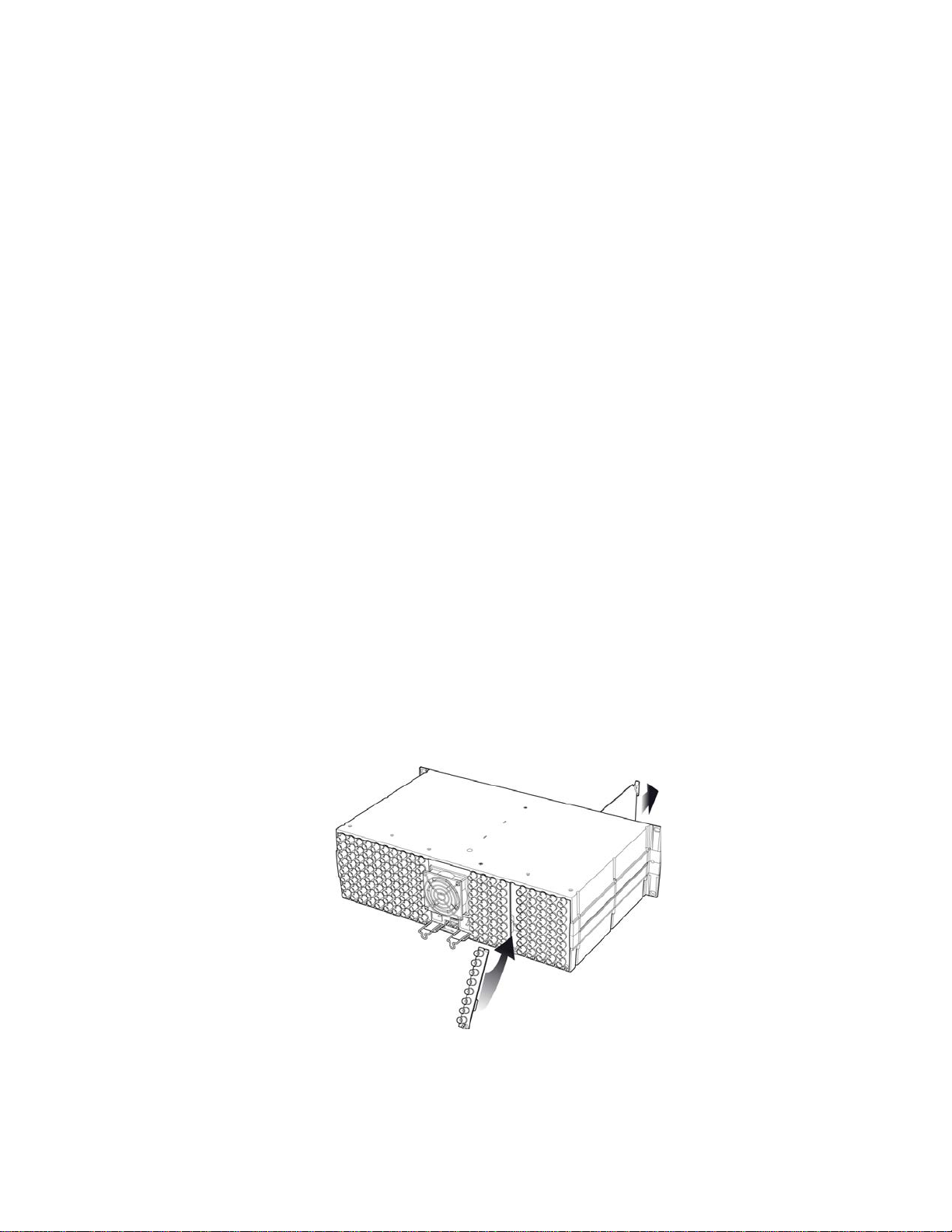
Insert the appropriate cartridge for your application into the Fiber I/O connector, and then connect the fibers to the
cartridge via the LC connectors.
•See ANNEX 2 on page 22 for a detailed description of the installation & removal procedure.
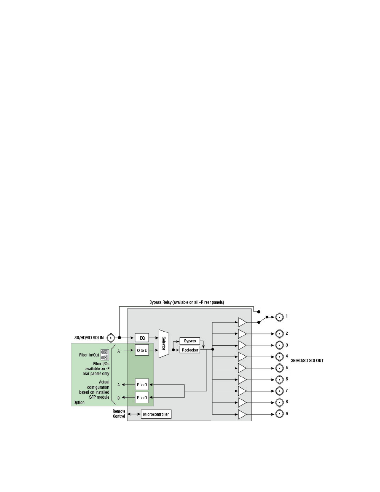
2.4 Bypass Relay
Rear panels with an integrated bypass relay are identified by a –R designation. The relay activates automatically if the
card loses power, or is removed from the frame.
When activated, the relay connects the 3G-HD-SD SDI input directly to 3G-HD-SD SDI output 1, ensuring that the
signal is available downstream.
When the card is re-activated, the relay disengages.

GUIDE TO INSTALLATION AND OPERATION
HDA-3911/31 | 7
3 Operation
3.1 Control Options
The HDA-39x1 can be controlled in two different ways:
•The local control panel and its push-buttons can be used to move through a menu of parameters and to adjust
parameter values (see section 3.3).
•Grass Valley’s iControl system can be used to access the card’s operating parameters from a remote computer,
using a convenient graphical user interface (GUI). (see section 3.4)
3.2 Card-Edge Status LED
The status monitor LED is located on the front card-edge of the HDA-39x1, and is visible through the front access door
of the DENSITÉ 3 frame. This multi-color LED indicates the status of the HDA-39x1 by color, and by flashing/steady
illumination.
The chart shows how the various error conditions that can be flagged on the HDA-39x1 affect the LED status.
•If a cell is gray, the error condition cannot cause the LED to assume that status
•If more than one LED status is possible for a particular error condition, the status is configurable.
See Section 3.4.6 for details.
•The factory default status is shown by a
The LED will always show the most severe detected error status that it is configured to display, and in the chart error
severity increases from left to right, with green representing no error/disabled, and flashing red the most severe error.
LED Status
Error Condition
Green
Yellow
Red
Flashing
Red
No input signal presence
No lock on input signal
No fiber present when needed
No rear
: Factory default.
If the LED is Flashing Yellow, it means that the card is selected for local control using the Densité frame’s control
panel. See Section 2.7 for details.
The LED will be Yellow when the card is in the “Firmware Update” mode.

GUIDE TO INSTALLATION AND OPERATION
8| HDA-3911/31
3.3 Local control using the Densité 3 frame control panel
3.3.1 Overview
Push the SELECT button on the HDA-39x1 card edge
(see Section 1.4) to assign the local control panel to
operate the HDA-39x1. Use the control panel buttons to
navigate through the menu, as described below.
All of the cards installed in a Densité 3 frame are
connected to the frame’s controller card, which handles
all interaction between the cards and the outside world.
There are no operating controls located on the cards
themselves. The controller supports remote operation
via its Ethernet ports, and local operation using its
integrated control panel.
The local control panel is fastened to the front of the
CPU-ETH2 controller card, and when installed is located in the front center of the frame, positioned in front of the
power supplies. The panel consists of a display unit capable of displaying two lines of text, each 16 characters in
length, and five pushbuttons.
The panel is assigned to operate any card in the frame by pushing the SELECT button on the front edge of that card.
•Pushing the CONTROLLER button on the control panel selects the Controller card itself.
•The STATUS LED on the selected card flashes yellow.
The local control panel displays a menu that can be navigated using the four pushbuttons located beside the display.
The functionality of the pushbuttons is as follows:
[+] [–] Used for menu navigation and value modification
[SELECT] Gives access to the next menu level. When a parameter value is shown, pushing this button once
enables modification of the value using the [+] and [–] buttons; a second push confirms the new value
[ESC] Cancels the effect of parameter value changes that have not been confirmed; pushing [ESC] causes the
parameter to revert to its former value.
Pushing [ESC] moves the user back up to the previous menu level. At the main menu, [ESC] does not
exit the menu system. To exit, re-push the [SELECT] button for the card being controlled.
If no controls are operated for 30 seconds, the controller reverts to its normal standby status, and the selected card’s
STATUS LED reverts to its normal operating mode.
3.3.2 Menu for local control
The HDA-39x1 has operating parameters which may be adjusted locally at the controller card interface.
•Press the SELECT button on the HDA-39x1 front card edge to assign the Densité 3 frame’s local control
panel to the HDA-39x1
•Use the keys on the local control panel to step through the displayed menu to configure and adjust the HDA-
39x1.
The complete menu structure is shown in Annex 1 to this document, beginning on page 20.
Figure
3.1 Densité 3 Frame local control panel

GUIDE TO INSTALLATION AND OPERATION
HDA-3911/31 | 9
3.4 Remote control using iControl
The operation of the HDA-39x1 may be controlled using Grass Valley’s iControl system.
•This manual describes the control panels associated with the HDA-39x1 and their use.
•Please consult the iControl User’s Guide for information about setting up and operating iControl.
•Exception: At the time of printing, the HDA-39x1 was not supported by iControl Solo
In iControl Navigator or iControl Websites, double-click on the HDA-39x1 icon to open the control panel.
3.4.1 The iControl graphic interface window
The basic window structure for the HDA-39x1 is shown in figure 3.2. The window identification line gives the card type
(HDA-3911 or HDA-3931) and the slot number where the card is installed in its Densité frame.
Figure 3.2 HDA-3931 iControl graphic interface window:
There are three main sections in the window itself, shown in Figure 3.2:
1. The top section displays icons on the left. These icons report the
status of some parameters associated with this HDA-39x1. Figure 3.3
shows the three icons that may appear.
Move the mouse over an icon and a status message appears below the
icon providing additional information.
If there is an error, the error status message appears in the message
area without mouse-over.
•If there are multiple errors, the error messages cycle
•The icon whose status or error message is shown is highlighted
with a mauve background
1
2
3
Figure 3.3 iControl Status Icons
Icon # 1 2 3

GUIDE TO INSTALLATION AND OPERATION
10 | HDA-3911/31
The table below lists the various status icons that can appear, and how they are to be interpreted.
•In cases where there is more than one possible interpretation, read the error message in the iControl window to
see which applies.
Table – iControl Status Icon interpretation
Icon #1 – Manual Card Configuration
(green)
Remote card control activated. The iControl interface can be used to operate the card
(yellow)
Local card control active. The card is being controlled using the Densité 3 frame control
panel, as described in section 3.3. Any changes made using the iControl interface will have
no effect on the card.
Icon #2 – Input A status
(green)
Signal detected and valid.
•Beneath the icon, the format will be indicated as 3G, HD or SD, and the specific
format details will be listed if the cursor is moved over the icon.
(red)
Input signal error
No rear
(grey)
No electrical input
Icon #3 – Input B status (only on HDA-3911)
(green)
Signal detected and valid.
•Beneath the icon, the format will be indicated as 3G, HD or SD, and the specific
format details will be listed if the cursor is moved over the icon.
(red)
Input signal error
No rear
(grey)
No electrical input
2. The center portion of the iControl graphic interface window contains a series of control and information panels,
selected by tabs.
•Click on a tab to display the associated panel.
•Each of these panels is described individually in the following sections.

GUIDE TO INSTALLATION AND OPERATION
HDA-3911/31 | 11
3. The Load Factory button is always visible at the bottom of the panel. Click the Load Factory button to reset all
parameters on this HDA-39x1 card to factory default values.
•The factory default values are shown underlined in the menus found in the Annex to this document, beginning
on page 20.
3.4.2 The Input panel
This panel allows the user to
select the input that will be
processed through the
available channels in the
HDA-39x1.
HDA-3911: Only one channel
is available, so
channel B does
not appear in the
panel
HDA-3931: Two channels are
available. The
rear panel may
have one or two
electrical inputs,
and may have two
optical inputs.
Channel B will be
greyed out if no
signal is available
for it.
Input Config
Select the input for Channel A and Channel B, using the radio buttons.
•Electrical Input A and Optical Input A can only go to Channel A
•Electrical Input B can only go to Channel B
•Optical Input B can go to either Channel A or Channel B
Reclocker
Use the radio buttons to independently turn the reclockers for Channels A and B ON or OFF
Figure 3.4 Input panel – HDA-3911 (left) and HDA-3931 (right)

GUIDE TO INSTALLATION AND OPERATION
12 | HDA-3911/31
3.4.3 The Rear panel
This panel identifies the type of rear panel installed with this HDA-39x1.
The name of the installed rear panel appears in the data box.
•If no rear is installed, “No Rear” appears in the data box.
3.4.4 The Status panel
This panel shows the status of the various inputs to this HDA-39x1.
For HDA-3911, only IN A is shown, because there is no IN B,
Electrical inputs (A and B)
Data rate (270 Mbps / 1.5 Gbps / 3 Gbps) – the detected input data rate is
indicated by a green status icon
No Lock / No Signal – either of these conditions is indicated by a red
status icon
Fiber
Module type: the type of fiber module installed in the rear panel will be
shown in the text box:
None
Single RX
Single TX
Dual RX
Dual TX
Bidirectional
Figure 3.6 Status panel
Figure 3.5 Rear panel

GUIDE TO INSTALLATION AND OPERATION
HDA-3911/31 | 13
3.4.5 The Output panel
This panel has two functions related the HDA-39x1 output:
Output Config
If an optical output is available, use the radio buttons to independently turn
the two optical outputs OFF or ON
•Optical output is only available for rear panels with a Fiber I/O
connector and an installed output (TX) cartridge
•Optical output A, if available, can only carry channel A
•Optical output B, if available, can carry either Channel A or Channel
B on an HDA-3931, and the choice is made here. On an HDA-3911,
only channel A is available, because there is no channel B.
3.4.6 The Alarms panel
This panel allows the alarm reporting of the HDA-39x1 to be configured.
Click on the Alarm Config button to open the Alarm Configuration window.
Figure 3.8Alarms panel and Alarm Configuration window
Figure 3.7 Output panel

GUIDE TO INSTALLATION AND OPERATION
14 | HDA-3911/31
The Alarm Configuration window is organized in columns
Status/Name
This contains an expandable tree listing all the alarms reported by this HDA-39x1 card.
•Each alarm name includes an icon that shows its current status
The Card LED, Overall alarm and GSM contribution columns contain pulldown lists that allow the level of
contribution of each individual alarm to the alarm named in the column heading to be set.
•If there is no arrowhead in the box, there is no pulldown and the alarm is not user-configurable
Card LED
This column allows configuration of the contribution of each individual alarm to the status reported by the Status
LED on the front edge of the HDA-39x1 card, visible through the front door of the Densité frame.
Overall Alarm
This column allows configuration of the contribution of each individual alarm to the Overall Alarm associated with
this card. The Overall Alarm is shown in the upper left corner of the iControl panel, and also appears at the bottom
of the Status/Name column.
GSM Contribution
This column allows configuration of the contribution of each individual alarm to the GSM Alarm Status associated
with this card. GSM is a dynamic register of all iControl system alarms, and is also an alarm provider for external
applications. The possible values for this contribution are related to the Overall alarm contribution:
•If the Overall alarm contribution is selected as Disabled, the GSM alarm contribution can be set to any available
value
•If the Overall alarm contribution is selected as any level other than disabled, the GSM contribution is forced to
follow the Overall Alarm.
Levels associated with these alarms:
The pulldown lists may contain some or all of the following options:
The alarm makes no contribution (black icon)
The alarm is of minor importance (yellow icon)
The alarm is of major importance (orange icon)
The alarm is of critical importance (red icon)
The alarm exists but has no effect (used for text and composite alarms)
Shortcut: if you click on one of the “Set All” boxes in the Card LED, Overall Alarm or GSM Contribution columns,
you will open a pulldown that lets you assign a level to all alarms in that section of the column simultaneously.
Log Events
iControl maintains a log of alarm events associated with the card. The log is useful for troubleshooting and identifying
event sequences. Click in the checkbox to enable logging of alarm events for each individual alarm.
At the bottom of the window are several other controls.

GUIDE TO INSTALLATION AND OPERATION
HDA-3911/31 | 15
Copy to other cards
Click this button to open a panel that allows the alarm
configuration set for this card to be copied into another
HDA-39x1 card.
•Select one or more destination cards from the list
in the window by clicking in the checkboxes, or all
of them by clicking in the All checkbox
Get alarm keys
Click this button to open a save dialog where you can
save a file containing a list of all alarms on this card and
their current values, along with an Alarm Key for each.
The alarm keys are useful for system integration and
troubleshooting.
•The file is saved in .csv format
OK, Apply, Cancel
•OK accepts the settings and closes the window once the card confirms that there are no errors.
•Apply accepts the settings, but leaves the window open
•Cancel closes the window without applying any changes, and leaves the previous settings intact.
Figure 3.9Copy to Other Cards
Figure 3.10 Save dialog for Get Alarm

GUIDE TO INSTALLATION AND OPERATION
16 | HDA-3911/31
3.4.7 The Info panel
When the HDA-39x1 is included in an iControl environment, certain
information about the card should be available to the iControl system. The
user can enter labels and comments that will make this card easy to
identify in a complex setup. This information is entered into data boxes in
the Info control panel.
Label: type the label that is shown for this HDA-39x1 when it
appears in iControl applications
Short Label type the short-form label that iControl uses in some cases
(8 characters)
Source ID type a descriptive name for this HDA-39x1
Comments: type any desired text
The remaining data boxes show manufacturing information about this
card.
Three buttons in the panel give access to other information.
•Details…: Reports the Firmware version, service version, and panel
version for this card
•Advanced…: Shows the Long ID, which is the address
of this HDA-39x1 in the iControl network.
Figure 3.11 Info panel
Figure 3.12 Details window
Figure 3.13 Advanced window
This manual suits for next models
1
Table of contents
Other Belden Amplifier manuals

Belden
Belden Grass Valley VEA-1023 Instruction Manual

Belden
Belden Grass Valley HDA-1911 Instruction Manual

Belden
Belden grass valley IQSDA41 Series User manual

Belden
Belden GRASS VALLEY HDA-3961 Instruction Manual

Belden
Belden GRASS VALLEY HDA-1941 Instruction Manual

Belden
Belden Grass Valley DDA-1133 Instruction Manual

Belden
Belden PPC Entry Series User manual