nplifier. Otherwise malfunction may
SUlt.
CA
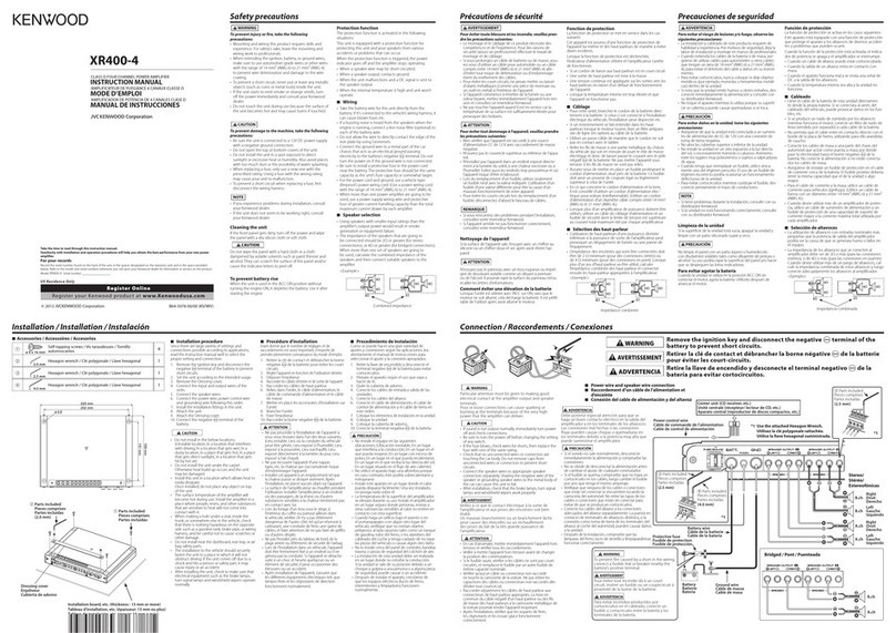
cable ground lead terminal
'henusingan RCA cable with
a
ground
3d attached, connectthe ground leadto
is terminal.
fNE IN terminal
fNE
OUT
terminal
iese jacks output respectivelythe signals
put to amplifiers A and B.They always
itput the stereo signals regardlessof the
)sition of the OPERATIONswitch.
peaker level input terminals
The genuine-accessorycar stereo shall
lave
a
maximum power output of no
norethan
40
W.
30 not connectthe speaker output leads
from
a
power amplifier (Optional)to the
speaker levelinput terminals of this unit,
for this may cause malfunction or
rlamage.
Do
not connect cables and leadsto both
RCA cable inputjacks and the speaker
level input terminals simultaneously,for
this may cause malfunction or damage.
Connect the power control leadto
a
power supply which can be turned
ON/OFF by the ignition key switch (ACC
line).With this connection,shock noise
may begeneratedwhen the power
of
the
genuine-accessorycar stereo is switched
ON/OFF.
X5E-j
H
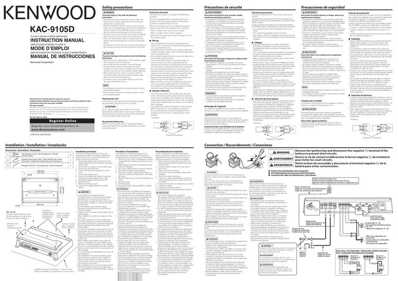
Installationprocedure
Since there are large variety of settings and
connectionspossible accordingto applications,
read the instruction manualwell to select the
proper setting and connection.
1,
Remove the ignition key and disconnectthe
negative
@
terminal of the battery to
preventshort circuits.
2.
Set the unit accordingto the intended usage.
3.
Connectthe input and output wires of the
4.
Connectthe speaker wires.
5.
Connectthe power wire, power control wire
and groundingwire following this order.
6.
Installthe unit in the car.
7.
Connectthe negative
@
terminal of the
battery.
units.
I
AWARNING
I
To preventfire caused by
a
short inthe wiring,
connect
a
fusible link or breakernearbythe
battery's positiveterminal.
1
ACAUTION
1
If sound is not output normally, immediately
turn power off and check connections.
Be sure to turn the power off before
changingthe setting of any switch.
If
the fuse blows, check wires for shorts,
then replacethe fuse with one of the same
rating.
connectorsare touchingthe car body.
Do
not removecaps from unconnectedwires or
connectorsto prevent short circuits.
Connectthe speakerwires to appropriate
speaker connectorsseparately. Sharing the
negativewire of the speaker or grounding
speaker wires to the metal body of the car
can cause this unit to fail.
lamps, winkers, and wipers work properly.
1
Check that no unconnectedwires or
1
*After installation,check that the brake
H
Wiring
Take the battery wire for this unit directly
from the battery. If it'sconnectedto the
vehicle's wiring harness,it can cause blown
fuses etc.
If
a
buzzingnoise is heardfrom the speakers
when the engine is running, connect
a
line
noisefilter (optional)to each of the battery
wire.
Do
not allow the wire to directly contactthe
edge of the iron plate by usingGrommets.
Connectthe ground wire to
a
metal part of
the car chassisthat acts as an electrical
ground passingelectricity to the battery's
negative
@
terminal.
Do
not turn the power
on if the groundwire is not connected.
Be sure to install
a
protective fuse in the
power cord near the battery.The protective
fuse should be the same capacityas the
unit's fuse capacityor somewhat larger.
For the power cord and ground, use
a
vehicle
type (fireproof)power wring cord with
a
current capacitygreater than the unit's fuse
capacity. (Use
a
power wiring cord with
a
diameter
of
5
mm2(AWG
10)
or greater.)
When morethan one power amplifier are
goingto be used, use
a
power supply wiring
wire and protective fuse of greater current-
handlingcapacitythan the total maximum
current drawn by each amplifier.
W
Speaker Selection
*The ratedinput power of the speakersthat
are goingto be connectedshould be greater
than the maximumoutput power (inWatts) of
the amplifier. Use
of
speakershavinginput
power ratingsthat are lessthan the output
power of the amplifierwill cause smoke to be
emitted
as
well as damage.
*The impedance
of
the speakersthat are
goingto be connectedshouldbe
2Q
or
greater (for stereo connections),or
4Q
or
greater (for bridgedconnections).When more
than one set of speakersare goingto be
used, calculatethe combinedimpedanceof
the speakers and then connect suitable
speakersto the amplifier.
4
Q
1..
...
4Q
0..
Combined impedance
English
7


