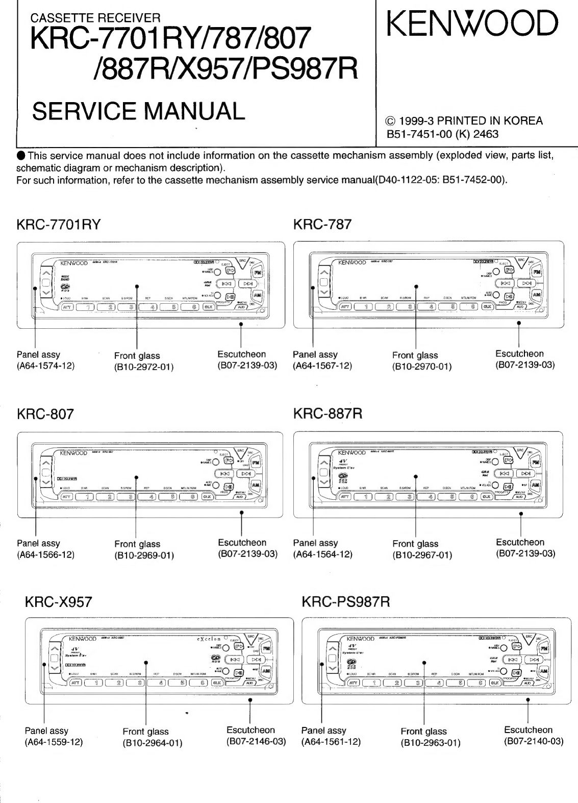
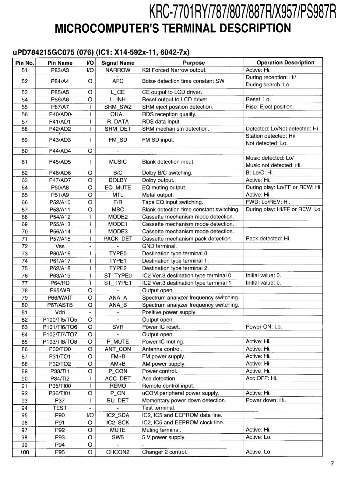
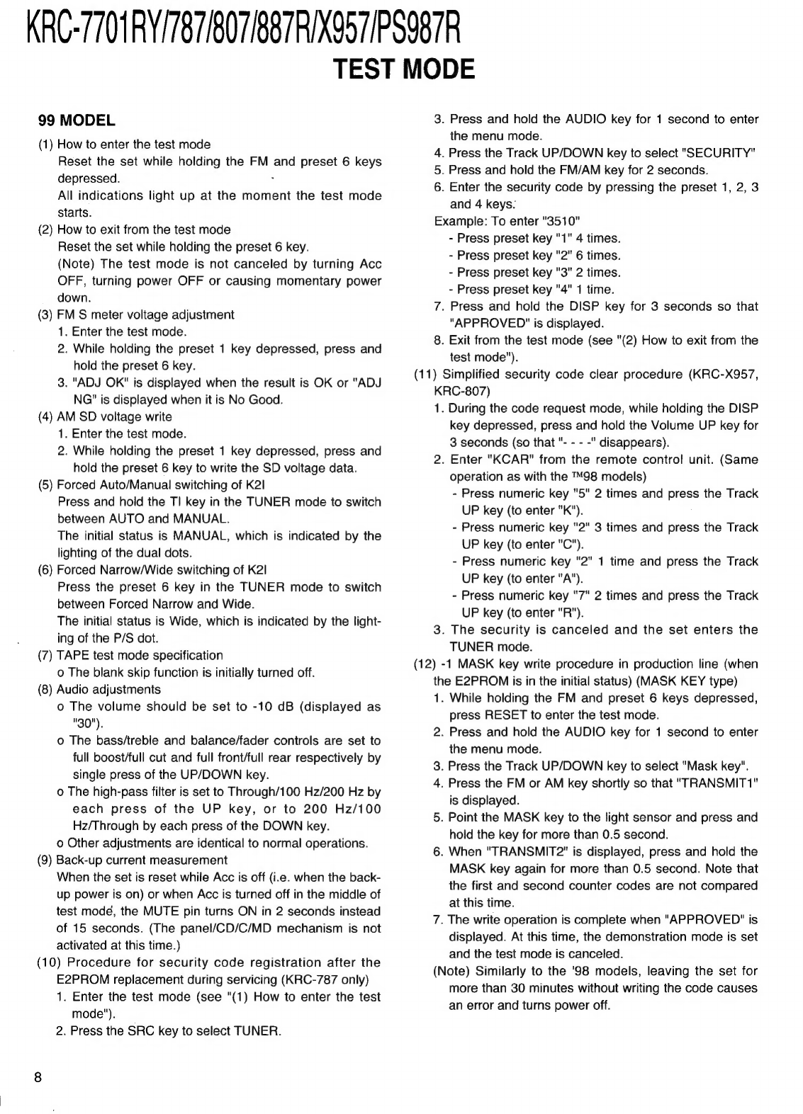
Kenwood KRC-7701RY User manual
Other Kenwood Car Receiver manuals

Kenwood
Kenwood KRC-265 User manual

Kenwood
Kenwood KDC-U559BT User manual

Kenwood
Kenwood DDX7015 - Excelon - DVD Player User manual

Kenwood
Kenwood KDC-U7056DAB User manual

Kenwood
Kenwood KRC-705 User manual

Kenwood
Kenwood KDC-MP242 - Radio / CD User manual

Kenwood
Kenwood KDC-BT365U User manual

Kenwood
Kenwood KRC-777R User manual

Kenwood
Kenwood KDC-X915 User manual

Kenwood
Kenwood KDC-2029 User manual

Kenwood
Kenwood KDC-DAB361U User manual

Kenwood
Kenwood KDC-X993 - eXcelon Radio / CD User manual

Kenwood
Kenwood EZ700SR User manual

Kenwood
Kenwood KDC-1028 User manual

Kenwood
Kenwood KRC-S100 User manual

Kenwood
Kenwood KDC-307 User manual

Kenwood
Kenwood KDC-252U User manual

Kenwood
Kenwood KRC-108S User manual

Kenwood
Kenwood KVT-512 User manual

Kenwood
Kenwood KRC-280 User manual