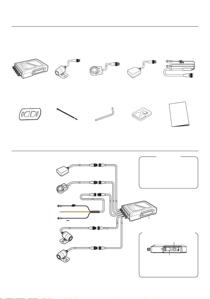
Kenwood STZ-RF200WD User manual

2
• La información actualizada (el manual de instrucciones más reciente, etc.)
está disponible en <https://www.kenwood.com/cs/ce/>.
Para sus registros.
Registre el número de serie, situado en la parte posterior de la unidad en los espacios
designados en la tarjeta de garantía, en el espacio provisto a continuación. Consulte el
modelo y los números de serie siempre que pueda con su distribuidor Kenwood para
obtener información o servicio sobre el producto.
Modelo STZ-RF200WD
Número de serie______________
Solo residentes de EE. UU.
Registro en línea
Registre su producto KENWOOD en www.kenwood.com/usa
• Des informations mises à jour (le dernier Manuel d’instructions, etc.) sont
disponibles sur <https://www.kenwood.com/cs/ce/>.
Pour vos enregistrements
Enregistrez le numéro de série qui se trouve à l’arrière de l’unité, dans les espaces
désignés sur la carte de garantie et dans l’espace prévu ci-dessous. Reportez-vous aux
numéros de modèle et de série à chaque fois que vous le pouvez auprès de votre reven-
deur Kenwood pour obtenir des informations ou des services sur le produit.
Modèle STZ-RF200WD
Numéro de série______________
Résidents des États-Unis uniquement
Enregistrer en ligne
Enregistrez votre produit KENWOOD sur www.kenwood.com/usa
• Updated information (the latest Instruction Manual, etc.) is available from
<https://www.kenwood.com/cs/ce/>.
For your records
Record the serial number, found on the back of the unit in the spaces designated on the
warranty card, and in the space provided below. Refer to the model and serial numbers
whenever you can upon your Kenwood dealer for information or service on the product.
Model STZ-RF200WD
Serial Number______________
US Residents Only
Register Online
Register your KENWOOD product at www.kenwood.com/usa

3
Motorsports CAM
STZ-RF200WD
INSTRUCTION MANUAL
Read this manual thoroughly before installation wiring and use. Install and wire the unit correct-
ly in accordance with the Safety Precautions (
Please store this manual in a secure location and refer to it as needed.
In the event of an accident or damage to the motorsports vehicle which the
unit is installed
from being overwritten. ()
English
Contents
Safety Precautions .......................................... 4
Precautions for Use.........................................
FCC/IC............................................................. 9
Check the Items Included in the Package ..... 10
Name and Function of Each Part .................. 10
Installation ......................................................11
Motorsports CAM Functions.......................... 15
Using the Cell Phone App..............................
Using the Computer Viewing Program .......... 19
Updating the Firmware .................................. 19
Troubleshooting............................................. 20
Appendix........................................................ 22
.................... 25
................................................ 26

4
Safety Precautions
These symbols denote explanations to prevent injuring yourself and others,
and prevent damage to property.
Warning Describes information that could result in death or serious injury if not followed.
Caution Describes information that could result in bodily injury or damage to property.
This icon indicates important cautions (and warnings).
This icon indicates actions to avoid (prohibited actions).
This icon indicates actions that must be taken (mandatory and indicated actions).
Warning
Installation and Wiring
• Do not install equipment in locations that interfere with line-of-sight or vehicle op-
erations or in locations that pose a danger to passengers
• Do not install equipment in locations subject to high temperatures, such as close
to the engine, muer, etc.
• Ensure that installed equipment and the ground wire do not use a nut or bolt from
the vehicle’s safety systems (handlebar, brakes, gas tank, etc.)
• Do not let water or foreign matter enter the unit
• Ask a specialist to install and wire the unit for safety
• Install and wire the unit as described in this instruction manual
• Install wires so that they do not interfere with steering the vehicle
• Use tape to insulate any bare sections on wires
• Check that the vehicle’s electronic components operate properly after installation
and wiring

5
• Store SD cards, packing materials or unused accessories such as screws in a lo-
cation away from small children.
• Plug in the power cable correctly
• Hold the in-line connectors when unplugging the power cable
• Disconnect the in-line connector for power cable when not using the Motorsports
CAM for extended periods of time
• Make sure to use the included parts and specied components
• Clean the power cable at the battery connection point periodically
Use
• Do not remove the SD card or disconnect in-line connectors with wet hands.
• Do not disassemble repair or try to modify the unit.
Telecommunications Business Act.
• This unit is intended only for vehicles with a DC 12V power supply.
Using this unit in any other voltage environment besides 12V DC such as 6V, 24V or other
• Do not use if damaged or malfunctioning.
If foreign matter enters the unit, or if it produces smoke, abnormal noise, or peculiar
odors, stop use immediately and disconnect the power cable.
• Never use the associated cell phone app while driving.
Only use it once you have parked in a safe location.
• Can we say use caution when using the switch or the need to glance at the status
indicator.
Driving safely should be prioritized.
• Do not conduct risky behavior, such as sudden starts or braking, to test whether
the unit is working.
• Do not use the unit if there is condensation on it.
It could result in malfunctions, heat buildup, or electric shocks.
• Do not subject the unit to strong impacts, like drops, hits, etc.
It could result in malfunctions or damage.
• Do not place items with strong magnetic elds near the unit
It could result in a malfunction.
• Do not let the unit come into contact with gasoline, liquids, organic solvents, brake
uids, etc.
It could result in malfunctions or damage.
• Do not wash the unit or camera when cleaning your vehicle with a pressure washer
It could result in a malfunction.
• Secure disconnected in-line connectors with tape to prevent water or foreign mat-
ter from entering
It could result in a malfunction.
• Always use fuses of the specied capacity and ask a specialist to replace them.

6
Handling near electronic medical equipment
If used near electronic medical equipment such as implantable pacemakers or implantable
cardioverter-debrillators, keep the unit at least 22 cm (8.664″) from such equipment.
The radio waves may negatively aect the operations of medical devices.
Contact for malfunctions
If a malfunction occurs, stop use immediately and contact the oce listed in this
manual. Continued use may result in unanticipated accidents, res, or electric shocks.
Caution
Installation and Wiring
Do not install in locations subject to high-pressure water or locations with high lev-
els of humidity, dust, or soot
Do not place items on top of the unit or that cover the unit.
Cautions when handling cables
-
tric shocks, and malfunctions from disconnections or shorts.
Cautions against deteriorated paint on the installation surface
deterioration.
Use
Do not use the unit for any non-vehicle use.
Check the installation before driving
A loose unit or connected component of the unit could fall or interfere with driving an cause
If you notice malfunctions in the unit
If you notice that the unit is malfunctioning in any way, refer to the Troubleshooting section ()
The unit is equipped with a GPS device.
Recorded drive data includes location information.

Precautions for Use
Installation
• Only install the unit with the key removed from
the vehicle’s ignition so that the engine does not
start unexpectedly.
• Install the unit in a location that will not interfere
with vehicle operations.
• Event recording may not work properly if a
mistake is made during installation. Refer to
the instruction manual for directions, the angle
of installation, etc. to install the unit properly.
()
• When using double-sided tape to install the unit,
location using a commercial cleaning cloth and
wait for the location to dry before proceeding. Re-
using tape, using general purpose double-sided
tape, etc. for the installation will result in weaker
adhesion power and presents a risk of the unit
camera in place.
• Wrap cables using cable ties or commercial soft
edge masking tape so that they do not interfere
with driving.
• Do not install in locations that will be subject to
or high pressures (when the suspension bottoms
out while someone is on the bike).
• Disconnect the in-line connectors on the power
cable when not using the unit for extended peri-
ods of time. It could drain the battery. Secure dis-
connected in-line connectors with tape to prevent
water or foreign matter from entering.
• Install hook-and-loop fastener across the entire
surface. Install the unit in a location where it will
not be dislodged by a sudden impact, such as
under the seat, etc.
Use
• Do not block or dirty the camera lens or place
•
• Our company bears no responsibility for the ac-
curacy, completeness, or suitability of recorded
content.
• Please regularly check that the unit is recording
-
tions have occurred in the unit or SD card.
• Always check that the indicator is not producing
any abnormal displays when the unit is powered
on.
• Always check the installation prior to use.
Copyrights
• In some instances, video, images, and audio
content may not be recorded without permission
from the copyright holder, even if used for per-
sonal enjoyment.
• Even if permission is obtained from the copyright
holder for video, images, and audio content, in
some instances, use may not be allowed for
viewing outside of personal enjoyment.
Caring for the unit
• Wipe the unit gently with a dry silicone or soft
cloth if it becomes dirty. If the unit is very dirty,
wipe away the dirt with a cloth moistened with a
the unit with a hard cloth or volatile substance
such as paint thinner or alcohol could result in
scratches, deformations, deterioration, or mal-
function.
• Images may not record clearly if the lens is dirty.
Check the lens for dirt before driving.
If the lens is dirty, gently wipe away the dirt using
a soft cloth moistened with water. Wiping force-
fully with a dry cloth may scratch the lens.

8
Recommended SD cards
Type microSDHC
microSDXC
Capacity 16 GB to 256 GB
Speed class
File system FAT32
Allocation size 64 KB
• We cannot guarantee the operations of every SD
card.
• We recommend using a high-durability SD that is
suited for repeated recording (dashcam).
•
time, the Status LED may show an error warning.
An SD Card may need to be re-formatted by the
App or computer for normal operation.
Precautions when using SD cards
• When using a commercially available SD card,
read the instruction manual included with the
card.
•
or removing an SD card. If the unit is powered on,
there is a risk of damage to data or the SD card.
• Always format new SD cards in the unit before
using them.
• Always check whether video is recording proper-
ly after inserting an SD card.
• Make sure to push or pull SD cards in the proper
direction and do not bend, force, or hit them.
Do not touch terminal pins directly with your
hands or let them get into contact with metal ob-
jects. There is a risk of data being damaged or
lost due to electric shock.
• Always make sure to back up (copy) important
unit as soon as possible. Data may be lost de-
pending on how SD cards are used.
Please be aware that our company is in no way
responsible for compensating any damages
caused from the loss of stored data.
• Formatting SD cards or deleting data using the
unit or formatting SD cards on a computer only
does not completely erase all data stored in SD
cards. When an SD card will no longer be used,
we recommend using commercially available
data deletion software for computers to com-
pletely erase all data in the SD card. Data inside
SD cards is managed at the responsibility of the
customer.
• SD cards are consumable products. We recom-
mend periodically replacing them with new ones
depending on how they are used.
• You may not be able to overwrite or delete data
on SD cards, even when used normally.
• As a rule, format your SD cards once a month.
• Do not place objects on top of SD cards, drop
them, or use force on them. Store them in a
clean, dry place with low humidity.
• The warranty does not cover equipment malfunc-
tions caused by SD cards.

9
FCC/IC
FCC WARNING
made.
FCC NOTE
• This equipment has been tested and found to comply with the limits for a Class B digital device, pursuant
to Part 15 of the FCC Rules. These limits are designed to provide reasonable protection against harmful
interference in a residential installation.
• This equipment may cause harmful interference to radio communications, if it is not installed and used
in accordance with the instructions. However, there is no guarantee that interference will not occur in a
particular installation. If this equipment does cause harmful interference to radio or television reception,
the interference by one or more of the following measures:
- Reorient or relocate the receiving antenna.
- Increase the separation between the equipment and receiver.
- Consult the dealer or a professional installation technician for help.
This transmitter must not be co-located or operated in conjunction with any other antenna or transmitter.
CAN ICES-3(B) / NMB-3(B)
IC (Industry Canada) Notice
This device contains license-exempt transmitter(s)/receiver(s) that comply with Innovation, Science and
Economic Development Canada’s license-exempt RSS(s). Operation is subject to the following two con-
ditions:
1. This device may not cause interference.
2. This device must accept any interference, including interference that may cause undesired operation
of the device.
CAUTION
This equipment complies with FCC/IC radiation exposure limits set forth for an uncontrolled environment
and meets the FCC radio frequency (RF) Exposure Guidelines and RSS-102 of the IC radio frequency
(RF) Exposure rules. This equipment has very low levels of RF energy that is deemed to comply without
maximum permissive exposure evaluation (MPE). But it is desirable that it should be installed and operat-
Supplier’s Declaration of Conformity
Trade Name: KENWOOD
Product: Dashboard Camera
Model Name: STZ-RF200WD
Responsible Party:
JVCKENWOOD USA CORPORATION
2201 East Dominguez Street,
Long Beach, CA 90810, U.S.A.
PHONE: 310 639-9000
THIS DEVICE COMPLIES WITH PART 15 OF THE FCC RULES. OPERATION IS SUBJECT TO THE
FOLLOWING TWO CONDITIONS:
1. THIS DEVICE MAY NOT CAUSE HARMFUL INTERFERENCE, AND
2. THIS DEVICE MUST ACCEPT ANY INTERFERENCE RECEIVED, INCLUDING INTERFERENCE
THAT MAY CAUSE UNDESIRED OPERATION.
Complies with
IMDA Standards
DB02771

10
Check the Items Included in the Package
Check that all items are included before installing the unit.
Main unit Camera (×2)
Switch
(with double-sided
tape attached)
GPS antenna
(with double-sided
tape attached) Power cable
Double-sided tape
(For cameras) (×2) Zip ties (×4) Hex key
microSDHC card
(32 GB) ×1
Instruction manual
(this manual)
Name and Function of Each Part
+
-
In-line connector
GPS antenna
Rear camera
Front camera
Switch
Fuse holder (3A)
ACC
Power cable (red wire)
Power cable (yellow wire)
Power cable (black wire)
Status LED
Main unit
Side door
SD card slot
Reset button-Insert a
pin into the hole and
press the button to
reset the unit.
Components inside the side door
• GPS antenna: 6.56 ft / 2 m
• Switch: 6.56 ft / 2 m
• Front camera: 6.56 ft / 2 m
• Rear camera: 6.56 ft / 2 m
• Power cable: 3.28 ft / 1 m
Cable length

11
Installation
Inserting and removing the SD card
Inserting an SD card
1. Open the side door to access the SD card slot.
2. Press the SD card into the SD card slot until you hear a click, then close the side door.
Top
Side door
SD card
Insert the SD card with the pins
facing the top of the unit.
•
• We strongly recommend using the unit to format SD cards before using them. See the KENWOOD
Motorsports CAM Operations Guide when formatting an SD card.
* You can read the KENWOOD Motorsports CAM Operations Guide on our company website.
https://www.kenwood.com/cs/ce
Removing an SD card
1. Open the side door to access the SD card slot.
2. The SD card will pop out a little when pressed gently.
Close the side door after removing the SD card.
• Close the side door properly so that it latches fully and there are no gaps.
Otherwise, water or foreign matter could enter and cause a malfunction.

12
Installing the unit
Installation layout
GPS antenna
Switch
Front camera
Main unit Install the main
unit with the cables
facing the front of
the vehicle.
Rear camera
• This installation layout is for reference. Actual installations will vary by motorcycle model.
• Main unit
Install the main unit underneath the seat.
When fastening the main unit to the vehicle, check that there is adequate room to open the SD card
slot side door.
Use the double-sided tape or hook-and-loop fastener as needed when fastening the main unit to the
vehicle.
• -
face) of the main unit as shown in the image on the right.
•
Hook-and-loop fastener may peel due to vibrations or impacts,
so use a location where impacts will not cause the unit to
dislodge.
•
any dirt or grease on the installation location with a commercially available cleaning cloth, and
install the unit after the location has dried. Reusing tape or using general purpose double-sided
•
or high pressures (when the suspension bottoms out while someone is on the bike).
Double-sided tape
Double-sided tape

13
• GPS antenna
Install the GPS device in a location where it can easily receive satellite signals, such as near the handle-
bars or on top of the gas tank. Remove the release paper from the double-sided tape before installing.
• Switch
Install the switch in a location that is easy to operate and will not interfere with safe operation of the
motorcycle, such as on or nearby the left handlebar.
Remove the release paper from the double-sided tape before installing.
• Front and rear cameras
itself.
-
ed), and cable ties as needed to secure the cameras in place.
After installation, use the KENWOOD Motorsports CAM App to check the video feed and adjust the
camera. See
•
location using a commercial cleaning cloth and wait for the location to dry before proceeding. Re-
using tape or using general purpose double-sided tape for installation will provide less adhesive
• Use cable ties to secure cables so that they do not droop. Improper wiring or securing could

14
• Power cable
Each wire in the power cable assembly connects to the bike battery.
Unscrew the battery’s negative/ground terminal. Then unscrew the positive terminal.
Place the round terminal on the power cable (red wire) on the battery’s positive terminal, then tight-
en with the original terminal screw.
Next, place the round terminal on the power cable (black wire) on the battery’s negative terminal,
then tighten with the original terminal screw.
When connecting the power cable’s yellow wire, make sure that it is connected properly to the ACC
power supply.
•
contacting the terminal, and then remove the positive terminal. Connecting starts with the pos-
itive terminal.
• Remove the key from the ignition to prevent short circuiting the unit.
• Consult a professional installation technician if wire connections are causing problems. Incorrect
installation or wiring may severely damage the motorcycle or cause an accident.
• Install the fuse holder in a location where it will not come into contact with water.
• Connecting cables
Connecting cables
1. Check the pin layout of the in-line connectors and align the pins when connecting them.
2. Tighten the locking nut to secure the connection.
Locking nut
Cable
In-line connector
Disconnecting cables
1. Loosen the locking nut.
2. Hold the cable by the in-line connector and disconnect it.
Cable
In-line connector
• Holding the cable when disconnecting could damage the cable. Always hold the in-line connec-
tors to release a connection.
• Be careful to not mix up the cables for the front and rear cameras. Cables for the rear camera
have a white marker tube.
• Securing cables
Secure each cable to the motorcycle using cable ties or electrical tape.
Make sure they do not interfere with the rider’s ability to control the bike.
• Check that the handlebar can rock back and forth and that the wires do not interfere with opera-
tions when the suspension bottoms out.

15
Powering the unit
When the bike’s ignition is set to ACC or ON and the unit is switched on, the unit will start continuous
recording after completing a system check. When the ignition is turned to OFF, the unit will automatically
* The LED lights may illuminate for approximately 30 seconds while powering down which is normal.
Motorsports CAM Functions
The unit records videos and saves them to the microSD card.
Always insert an SD card into the SD card slot before using the unit.
See for details.
Function settings
You can change the function settings for the unit using the KENWOOD Motorsports CAM App. See the
KENWOOD Motorsports CAM App Guide for details.
Recording functions
Continuous recording
The unit will start continuous recording when it powers on. The default setting is for each recorded minute
CAM App.
Event recording
Event recording will start if a sudden force is detected during continuous recording. The unit will record
Manual recording
Manual recording will start if the switch button is pressed during continuous recording.
Saving and overwriting recorded les
) for details.
Audio settings
Audio recording can be set to ON or OFF.
You can change the setting with the KENWOOD Motorsports CAM App.

16
LED status display
Blue
Orange
State LED display pattern
System check at start-up (from
startup to the start of recording)
Blue
Orange
Blue lit and orange blinks once per
second
• Continuous recording
(unsynchronized time)
• Continuous recording
(synchronized time)
Blue
Orange Blue lit, orange unlit
• Wireless LAN (waiting for
connection)
• Wireless LAN (connected)
Blue
Orange Orange lit, blue blinks once per second
• Event recording
• Manual recording
Blue
Orange Blue and orange lit
Error (press the switch to display
error details)
Blue
Orange Orange lit, blue unlit
Error details
Blue
Orange Orange lit, blue unlit
SD card error*
(displayed for 5 seconds)
Blue
Orange Blinks for 0.5 seconds over 5 seconds
Front camera error*
(displayed for 5 seconds)
Blue
Orange
Blue blinks for 0.5 seconds and orange
is lit over 5 seconds
Rear camera error*
(displayed for 5 seconds)
Blue
Orange
Blue is lit and orange blinks for
0.5 seconds over 5 seconds
GPS error*
(displayed for 5 seconds)
Blue
Orange
Blue is lit, orange will blink twice every
0.5 second with a 0.2 second interval
between each blink for 5 seconds
High temperature error*
(displayed for 5 seconds)
Blue
Orange
Blue will blink twice every 0.5 second
with a 0.2 second interval between each
blink and orange is lit for 5 seconds
Wired switch error*
(displayed for 5 seconds)
Blue
Orange
Blue and orange will both blink twice
every 0.5 second with a 0.2 second
interval between each blink for
5 seconds

Using the Cell Phone App
You can use the KENWOOD Motorsports CAM App to view and download videos recorded and saved to
the SD card. You can also change the unit settings.
Installing the KENWOOD Motorsports CAM App
Minimum system requirements (cell phone)
•
• iOS 11 or later
Search for the KENWOOD Motorsports CAM App on the Google Play Store or the App Store.
Then download and install the app on your cell phone.
• Check that your cell phone is connected to the internet (either via mobile data or WiFi).
Connect your cell phone to the unit using a wireless LAN connection
1. Press and hold the switch button on the unit for 3 seconds to switch to wireless LAN mode.
The orange status LED will light up and the blue one will blink. This shows that the unit is preparing to
connect to your cell phone.
2. Open the settings on your cell phone.
3. Set WiFi to ON.
Bring up the list of available networks.
4. Tap STZ_RF200WD_(serial number).
5. Enter the password, tap connect, and it will connect with the unit.
•
•
Check the KENWOOD Motorsports CAM Operating Guide on our company website for more
detailed operating instructions.
https://www.kenwood.com/cs/ce

18
Adjusting the eld of view
It will start with the live feed from the front camera.
Guide lines
•
•
• If it starts with the live feed from the rear camera, the front and rear camera connections are
incorrect. Check the camera cable connections.
2. Use the included hex key to loosen the bolt on the installation bracket.
Bolt
Make sure that the indentation on the back of the camera is facing up.
4. Once the adjustment is complete, tighten the bolt and lock the camera in place.

19
Using the Computer Viewing Program
The KENWOOD Motorsports CAM Viewer is a
computer program designed for viewing video re-
corded by the unit.
The program can be downloaded from our com-
pany website.
Check the product page for details.
Installing the software
Double-click the program installer downloaded to
your computer and follow the directions on your
screen to install the program.
Check the KENWOOD Motorsports CAM Viewer Operating Guide on our company website for
more detailed operating instructions.
https://www.kenwood.com/cs/ce
Updating the Firmware
1. Download the latest version from our company website and copy it to an SD card.
3. The Motorsports CAM will check the SD card when it starts up.
The orange status LED will light up when the update starts.
4. The unit will automatically restart once the update is complete and the blue LED will light up.
-
sports CAM main menu, and check that the latest version is installed.
•
Operating environment
Windows
Compatible OS Windows 10 (32-bit/64-bit)
CPU Intel Core i3 2GHz or better
Memory 2 GB or more
Display 1280 × 800 or greater
Sound Functions that can playback
PCM sound in Windows
Mac OS X
Compatible OS MAC OS 10.14 or later

20
Troubleshooting
Issue Cause / Solution
The indicator does not light
up even though the vehicle
ACC is ON.
yIs the fuse blown?
3Address the cause of the blown fuse and replace the fuse.
yIs the in-line connector for the power cable or switch cable
disconnected?
3Check the connections of the in-line connectors.
The orange status LED is
blinking. (see )
yPress the switch and the status LEDs will inform you of the error
details.
The display indicates an SD
card error. (see )
yIs the SD card inserted correctly?
3If there is no change after the SD card is inserted correctly, format
the SD card or replace it with a new one.
The display indicates a front
camera error. (see )
yIs the in-line connector for the front camera disconnected?
3Check the connections of the in-line connectors. (see )
The display indicates a rear
camera error. (see )
yIs the in-line connector for the rear camera disconnected?
3Check the connections of the in-line connectors. (see )
The display indicates
that the camera is not
connected while adjusting
the recording angle.
(see )
yIs the in-line connector for the camera cable disconnected?
3Check the connections of the in-line connectors. (see )
The display indicates a GPS
error. (see )
yIs the in-line connector for the GPS device disconnected?
3Check the connections of the in-line connectors. (see )
The display indicates that
the temperature is high.
(see )
y
frame rate to prevent heat from generating and continue recording.
Stop recording if the temperature does not drop.
The display indicates a
switch error. (see )
yIs the in-line connector for the switch disconnected?
3Check the connections of the in-line connectors. (see )
The camera and main unit
will generate heat during
use.
yIs it too hot to touch?
3It will heat up during use. Stop use immediately if it is too hot to
The time displayed on
recorded video is incorrect.
yIs the top of the GPS antenna covered by metal or something with a
metal coating?
3Remove the item covering it. Or move the GPS antenna to a
location where nothing will cover it. If the issue is not resolved, use
a dedicated cell phone app to synchronize the time.
Other manuals for STZ-RF200WD
1
Table of contents
Languages: