Kenwood FG-273 User manual

©PRINTED
IN
v
\N
FUNCTIONGENERATOR
FG-273
INSTRUCTION
MANUAL
KENWOODCORPORATION
KENWOOD

TABLE
OFCONTENTS
INTRODUCTION
3
FEATURES
3
PRECAUTIONS
• 4
SPECIFICATIONS
5
OPERATOR'S
CONTROLSANDINSTRUTONS•••8
FrontPanel8
Rear
Panel13
MAINTENANCE• 14
Aproductof
KENWOOD
CORPORATION
17-5,2-chome,Shibuya,Shibuya-ku,Tokyo150,Japan
2

INTRODUCTION
TheMODELFG-273Sweep/FunctionGenerator
providesofa functiongenerator,pulsegenerator,Sweep
oscillator,
andfrequencycounter.
FEATURES
•
1.
Wide-banddesign: sevenrangescover
full
oscillation
frequency
from
0.02Hzto2 MHz
2.
Selectableoutputofsinewaves,squarewaves,and
triangularwavesthroughone-touchoperation.
3.
TTL/CMOSsquarewaveoutputconnectorfacilitates
using
TTL-levelandCMOS-leveloutputsquarewaves
as
thesignalsourceforexperimentofa digitalcircuit.
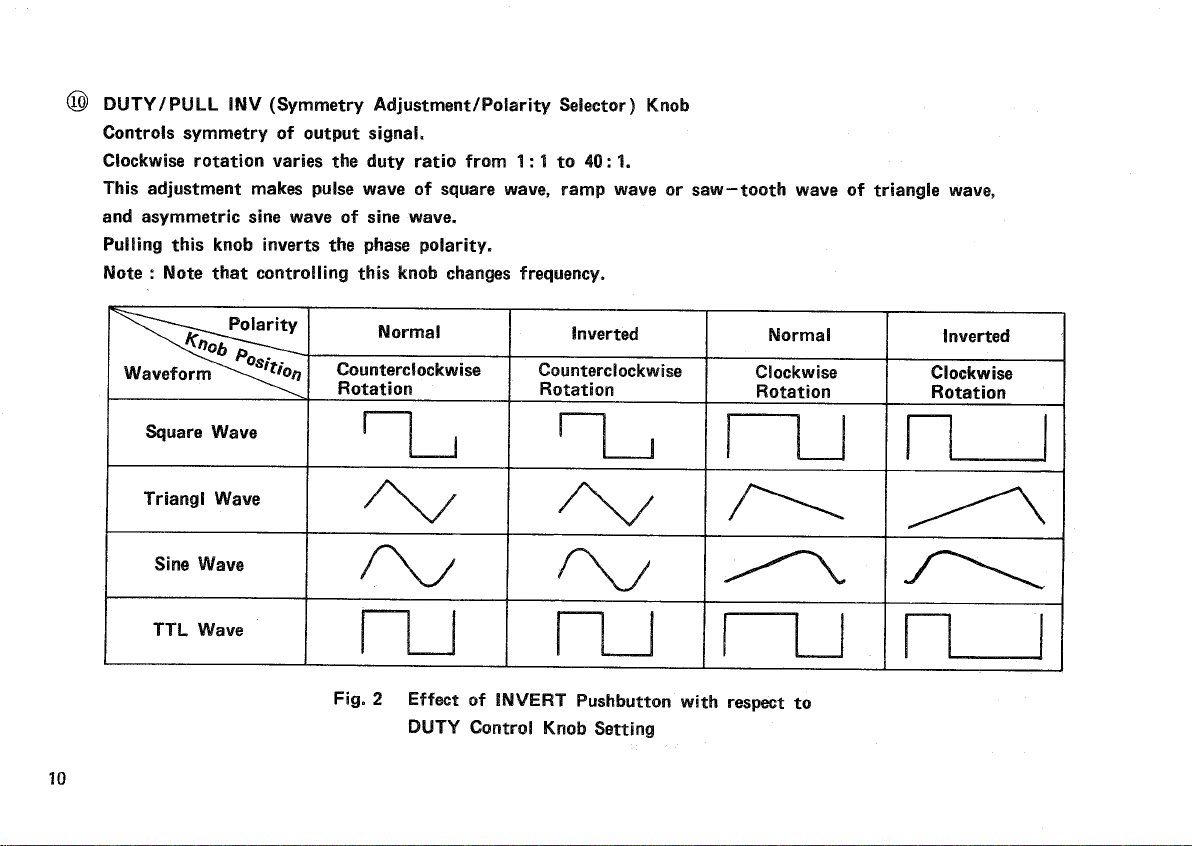
4.ThesymmetryFunctionvariessymmetryofsaw-tooth
waves
andpulsewaves.
Itcaninvertthewavepolarity.
5.Equipped
with
a 6-segmentLEDoscillationfrequency
display
anda countercoveringtherange
from
5 Hzto
10MHz.
6.Applyingvoltage
from
0 to+10V totheVCFIN
connector
implementsexternalsweepaswellasoutput
frequencycontrol.
7.Thelogsweepandlinearsweepfunctionprovides
sweep
frequencycontroluptomax.1000: 1.Sweep
frequencyisvariable
from
0.5Hz(2
seconds)
to50
Hz(20milliseconds).
Sweep
controlisimplementedbyapplyingsweepsignal
totheVCFconnector
from
anexternaldevice.
3.
DCvoltage(0to± 10V)canbeoverlaiduponoutput
waveform.
9.Combineduseofthe-20dBand-40dBATTENUA-
TOR
pushbuttonsandthecontinuousattenuator
providesmaximumattenuationover60dB.
10.A smallandlight-weight
case
with
convenient
carryinghandle,whichalso
serves
asa
tilting
stand.
3

PRECAUTIONS
1.
DonotusetheFG-273FunctionGeneratorunderthe
following
conditions:
-
Places
exposedtothedirectsunlight
-Veryhotandhumidrooms
-Rooms
with
excessive
mechanicalvibrations
-Neardeviceswhichirradiatestrongmagnetic
forces
orpulsevoltage
3.
DonotrepeatswitchingonandofftheGenerator.
4.Followtheinstructionsinsection" MAINTENANCE",
•ifthesupplyvoltageistobechanged.
2.
TheFG-273operatesimmediatelyafterturningon
power.
For
accuratemeasurement,however,waituntilit
warmsupsufficientlyafterpressingthePOWER
switch.
4

SPECIFICATIONS
<
FREQUENCY
CHARACTERISTICS
>
GENERAL
OutputWaveform• • • •
Sine
wave,squarewave,
trianglwave,pulsewave,TTL
/CMOS-level
squarewave,&
rampwave
Oscillation
FrequencyRange• • 0.02Hzto2 MHz
7ranges(1/10/100/1k/10k/
100k/1M)
Frequency
Accuracy(1)• • Max.± 1/4digits(Digital
display
tooutputfrequency)
Frequency
Accuracy(2)• • ± 5%offull
scale
(0.2Hto
2MHz)
( Frequencydialto
outputfrequency)
External
FrequencyControl(VCF)
InputVoltage0 to+10; frequency
increases
withpositive
voltage,max.± 20V (DC+
AC
peak)
Frequency
VariableRange• • • 1000: 1 ormore
SymmetryVariableRange• • • • 1 : 1 to40: 1 ormore
DC
Offset• •••••± 10V(opencircuit)
±5V (into50O)
continuous
variable
Polarity• Invertedornon-inverted
SINE
WAVE
Distortion1%or
less
(10Hzto100kHz)
OutputFrequency
Response
• • • Within± 1.0dBupto
100kHz(into50O , atmax.
output)
Output• • Variable
SQUARE
WAVE
Symmetry± 3%or
less
(at100Hz)
Rise/Fall
Time• • • • 100nsor
less
(atmax.output
level)
Output••••••••Variable
TRIANGL
WAVE
Linearity1%or
less
(at100Hz)
Output••Variable
5

TTL
OUTPUT
Rise/Fall
Time25nsor
less
Output
TTLlevel
CMOS
OUTPUT
Rise/Fall
Time60nsor
less
Output• Continuousvariable
from
+5
Vto+15V (High)
<SWEEP
CHARACTERISTICS
>
InternalSweepLinearorlogarithmic
Sweep
Frequency• • • • • 0.5Hz(2sec)to50Hz(20
msec),continuousvariable
Sweep
width
• • • • • • • 1 : 1 to1000: 1,peak-peak
variableandcontinuous
variable
External
sweepBymeansofVCFinput
<FREQUENCY
COUNTER
CHARACTERISTICS
>
Frequency
Range• • • 5 Hzto10MHz(1Osec,1 sec,
0.1
sec,
& 0.01sec)
Accuracy
• ••••••Referenceclockaccuracy± 1 count
Stability• ± 2x10"5or
less
(0to40°C)
InputSensitivity• • • • 30mVr.m.s.(5Hzto10MHz)
Max.InputVoltage• • 150Vr.m.s(at1kHz)
InputImpedance• • • • OdB: Approx,500k£l
-20dB: Approx,1MX1
<OUTPUT
CHARACTERISTICS
>
OutputVoltage• • • • 20Vppormore(opencircuit)
10Vppormore
(into
5012)
Attenuator• • • • • • -20dB/-40dBstep,orcontinuous
variable
Impedance• 50O±10%
6

<POWER
SUPPLY
>
Input
Voltage• • • • *
100/120/220/240
VAC± 10%
(Max.250VAC)
Frequency
• •
50/60
Hz
PowerConsumption• • Approx.20VA
<ENVIRONMENTALCONDITIONS>
StorageTemperature• • -20to60°C,70%or
less.
OperatingTemperature• 0 to40°C,80%or
less
With
Specifications• • 23± 5 °C,70%or
less
<SIZE& WEIGHT>
Dimensions(WHD)»•
240x
64x 190mm
Weight
1.8kg
<ACCESSORIES
>
Instruction
Manual
• • 1
AC
cable• • 1
Fuse
(0.3AT)1
(0.2A)
1
7

OPERATOR'S
CONTROLSANDINSTRUCTIONS
Fig.
1
8
FRONTPANEL

®POWERPushbutton
Pressing
thispushbuttonturnsonpower.Counter
display
fightsuptoindicatepowerison.
©CounterDisplay
Digitallydisplaysinternaloscillationfrequencyor
frequencyofexternalinputsignal.
©
OVER
LED
Lights
upwhenreadingonthecounterdisplay
overflows.
.
0
GATE
LED
Flashes
whenthegateisoperating.
©,©Hz/kHzLED
Indicatetheunitoffrequency,HzorkHz,aswellas
thedecimalpointwhen10s,1s,0.1s,or0.01s is
selected
with
thegate
time
selectorswitchassembly®.
©
FREQUENCY
Control
Variablepotentiometervariesfrequencywithinthe
rangeselected
with
theFreqoencyRANGEselector
switch
assembly®.Thedialis
scaled
from
0.2to2.0.
©
SWEEP
WIDTH
/
PULL
ONControl
Pullingtheknob
selects
internalsweep.Rotatingit
controls
sweepwidth.
Pushing
theknob
selects
externalsweep,whichis
implementedwhenexternalsweepvoltageisapplied
totheVCFinputconnector,
©
SWEEP
RATE
/
PULL
LOGControl
Controls
sweeprate(sweepfrequency)oftheinternal
sweep
oscillator.
Pullingtheknob
selects
logarithmicsweep.
9

©
DUTY/PULL
INV(SymmetryAdjustment/PolaritySelector)Knob
Controls
symmetryofoutput
signal.
Clockwise
rotationvariesthedutyratiofrom1:1to40:1.
This
adjustmentmakespulsewaveofsquare
wave,
rampwaveorsaw-toothwaveoftriangle
wave,
and
asymmetric
sine
waveof
sine
wave.
Pulling
thisknobinvertsthephasepolarity.
Note
:
Note
thatcontrollingthisknobchangesfrequency.
Normal Inverted Normal Inverted
Waveform^^^o/?
Counterclockwise
Rotation' ;
Counterclockwise
;Rotation
Clockwise
Rotation
Clockwise
Rotation
Square
Wave
TriangiWave
Sine
Wave
TTL
Wave
Fig.
2 EffectofINVERTPushbutton
with
respectto
DUTY
ControlKnobSetting
10

@
OFFSET/PULL
ADJControl
Pulling
thisknobadmixesDCvoltage
with
output
signal.
Clockwise
rotationadmixespositivevoltage.
Counterclockwise
rotationadmixesnegativevoltage-
Fig.
3 iillustratesseveraltypesofwaveform
with
the
OFFSET
knobpulledand50-ohmloadconnected.
ZeroDCoffsetatmax.signallevel
Offset
limit
fornon-clippingsignal
Positive
DCoffset NegativeDCoffset
Excessive
offset
Positive
DCoffset NegativeDCoffset
Fig.3
ApplicationExampleofDCOffset
11

©PUSHTTLKnob(CMOSLevel
Control
Knob)
PullingthecontrolvariesthelevelofCMOSsquare
waves
from
5Vpp
to15Vppcontinuously.
Rotatingtheknob,ifitisdepressed,
causes
no
variationinthelevelofTTLsquarewaves,
@
AMPLITUDEControl
Rotatingthis
control
varies
amplitude
of
output
waveform.
@
FrequencyRange/GateTimeSelectorSwitchAssembly
Selects
the
following
sevenrangesofoscillation
frequencyor
four
rangesof
gate
time
:
X1:
10s
0.2Hzto2 Hz
X10: A 2Hzto20Hz
X100: •1s 20Hzto200Hz
X1k:
J 0.2kHzto2 kHz
X10k: 0.1s 2 kHzto20kHz
X100k
:i 0.01s 20kHzto200kHz
X
1
M : I
0.01s 0.2MHzto2 MHz
(§)COUNTEREXTSelectorPushbutton
Pressing
thepushbutton
(button
engaged)selects
external
input
frequency.Anotherpress
(button
released)selectsinternaloscillationfrequency.
@
COUNTER-20dBPushbutton-
Pressing
thepushbuttonattenuatescounter
input
signalby20'dB.
@,@ATTENUATORPushbuttons
Pressing
thesepushbuttonsattenuates
output
signal
by20dBand40dBrespectively.
@
FUNCTIONSelectorSwitchAssembly
Selects
output
waveformoutofsinewave(),
triangl
wave(/\/),andsquarewave(H-i)•
@
TTL/CM
OS
Output
Jack
OutputsTTL-levelorCMOSsquarewaves.
®EXTCOUNTER
Input
Jack
Input
jackformeasuringfrequencyofexternalsignal.
®VCF
Input
Jack
By
applyingvoltagetothisjackinthestatewhere
the
WIDTH
pushbutton(8)isdepressed
(button
engaged),
frequencyof
output
signalcanbevaried.
Applicationofvoltage
from
0 to10Vvaries
frequencyuptomax,1000:1.
(§>
OUTPUT
Jack
Outputssinewave,
triangl
wave,orsquarewave
selected
with
theFUNCTIONselectorswitchassembly
@
.
12

REAR
PANEL
@
PowerConnector
Connector
forsupplyingACpower.
Use
thededicatedpowercord.
©
Fuse
Holder
Fuse
holderforACpowersupply.
Fig.
4
13

MAINTENANCE
1.
Fuse
Replacement
Ifthefusehasblownout,findoutandeliminatethe
cause.
Then,
replaceitwitha new fuse.Usea 0.3A slow-blowfuseforsupplyvoltageof100to120V , ora 0.2A
fuse
forsupplyvoltageof220to240V.
Fuse
holderisprovidedontherearpaneloftheunit.
2.
ChangingSupplyVoltage.
WARNING: Prior'to"opening'the
case,
besuretodisconnectthepowercord
from
the.socket,
2-1HowtoRemove
Case
To
openthe
case,
turntheunitupsidedown,andremovefour
screws
fromthe
case
baseplate.(SeeFig.5.)Then,
lift
thebaseplatetodetachit.
2-2HowtoChangeSupplyVoltage
The
FG-273isavailableforsupplyvoltageof100,120,220,and240VAC,50/60Hz.
To
changethesupplyvoltage,removethe
case
(inaccordancewithitem2-1above),andreconnectthevoltage
selector
plugontheprintedcircuitboardintheunittoa desiredvoltagepositiononthevoltageterminalboard.
(See
Fig.6.)
14

Screws
(4)
Power
transformer
Frontside
Fig.
6 Internal
selection
of
Supply
Voltage
Rubbershoe
Case
Fig.
5
Disassembly
and
Assembly
of
Case
Fuse
side
Voltage
selector
plug
-Voltageterminalboard
15
Rearside
Other manuals for FG-273
3
Table of contents
Other Kenwood Portable Generator manuals
Popular Portable Generator manuals by other brands

Generac Power Systems
Generac Power Systems GP Series owner's manual

Champion Global Power Equipment
Champion Global Power Equipment 92001i-EU Operator's manual

Firman
Firman P08013 Operator's manual

Escort
Escort EGC-3236A user manual

Firman
Firman W02985 owner's manual

Goodyear
Goodyear GY 2300I owner's manual