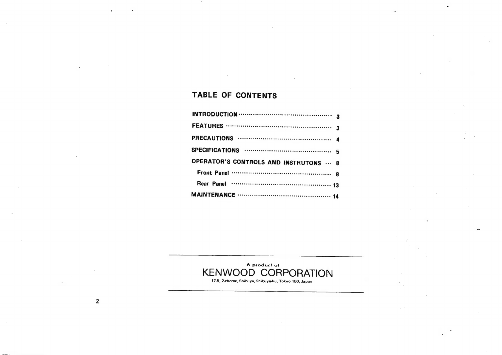
Kenwood FG-273 User manual

CGOOMNA
FUNCTION
GENERATOR
G-273
INSTRUCTION
MANUAL
KENWOOD
CORPORATION
3833

TABLE
OF
CONTENTS
INTRODUCTION
«-++-seseecessessescesscecseveceseesecseeaees
FEATURES
Sisceitiecttetin
gels
Btaen
el
cca
PRECAUTIONS
-ev-esssssscscecessescssccessececcassacscees
SPECIFICATIONS
--eseeseescseesessseseessecescescaceceees
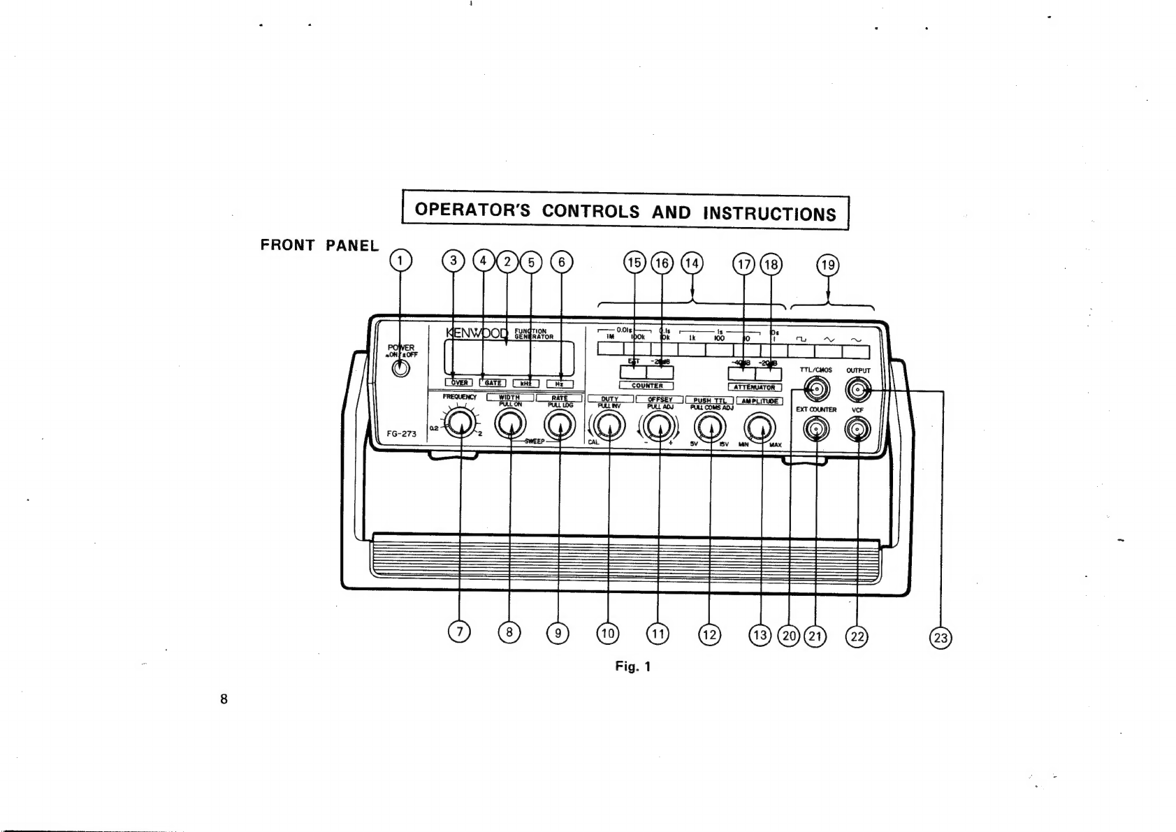
OPERATOR’S
CONTROLS
AND
INSTRUTONS
---
Fite
Panel
rcaistietscceatna
sania
druatstaleaisen
tis
Rear
Panel’
ahaniamdeiseawieeieteeksccnh
beret
MAINTENANCE
------:eecececccsccccsccccnccesscsececeeceses
A
product
ot
KENWOOD
CORPORATION
17-5,
2-chome,
Shibuya,
Shibuya-ku,
Tokyo
150,
Japan

INTRODUCTION
The
MODEL
FG—273
Sweep/
Function
Generator
provides
of
a
function
generator,
pulse
generator,
Sweep
oscillator,
and
frequency
counter.
FEATURES
Wide—band
design
:
seven
ranges
cover
full
oscillation
frequency
from
0.02
Hz
to
2
MHz
Selectable
output
of
sine
waves,
square
waves,
and
triangular
waves
through
one—touch
operation.
TTL/CMOS
square
wave
output
connector
facilitates
using
TTL—level
and
CMOS-—level
output
square
waves
as
the
signal
source
for
experiment
of
a
digital
circuit.
The
symmetry
Function
varies
symmetry
of
saw—tooth
waves
and
pulse
waves.
It
can
invert
the
wave
polarity.
Equipped
with
a
6—segment
LED
oscillation
frequency
display
and
a
counter
covering
the
range
from
5
Hz
to
10
MHz.
Applying
voltage
from
0
to
+10
V
to
the
VCF
IN
connector
implements
external
sweep
as
well
as
output
frequency
control.
10.
The
log
sweep
and
linear
sweep
function
provides
sweep
frequency
control
up
to
max.
1000:
1.
Sweep
frequency
is
variable
from
0.5
Hz
(2
seconds)
to
50
Hz
(20
milliseconds
).
Sweep
control
is
implemented
by
applying
sweep
signal
to
the
VCF
connector
from
an
external
device.
DC
voltage
(0
to
£10V)
can
be
overlaid
upon
output
waveform.
Combined
use
of
the
—20
dB
and
—40
dB
ATTENUA—
TOR
pushbuttons
and
the
continuous
attenuator
provides
maximum
attenuation
over
60
dB.
A
small
and
light-weight
case
with
convenient
carrying
handle,
which
also
serves
as
a
tilting
stand.

PRECAUTIONS
Do
not
use
the
FG—273
Function
Generator
under
the
3.
Do
not
repeat
switching
on
and
off
the
Generator.
following
conditions
:
—
Places
exposed
to
the
direct
sun
light
4.
Follow
the
instructions
in
section
“MAINTENANCE”
—
Very
hot
and
humid
rooms
if
the
supply
voltage
is
to
be
changed.
~
Rooms
with
excessive
mechanical
vibrations
—
Near
devices
which
irradiate
strong
magnetic
forces
or
pulse
voltage
The
FG—273
operates
immediately
after
turning
on
power.
For
accurate
measurement,
however,
wait
until
it
warms
up
sufficiently
after
pressing
the
POWER
switch.

SPECIFICATIONS
<FREQUENCY
CHARACTERISTICS
>
GENERAL
Output
Waveform
« «
« «
Sine
wave,
square
wave,
triang!
wave,
pulse
wave,
TTL
/CMOS~-level
square
wave,
&
ramp
wave
Oscillation
Frequency
Range
« *
0.02
Hz
to
2
MHz
7
ranges
(1/10/100/1k/10k/
100k
/1M)
Frequency
Accuracy
(1)
«
*Max.
+
1/4
digits
(Digital
display
to
output
frequency
)
Frequency
Accuracy
(2)
*
«+
5%
of
full
scale
(0.2H
to
2MHz)
(
Frequency
dial
to
output
frequency
)
External
Frequency
Control
(
VCF)
Input
Voltage
+
* « « *
0
to
+10
;
frequency
increases
with
positive
voltage,
max.
+
20
V
(DC
+
AC
peak
)
Frequency
Variable
Range
« * *
1000:
1
or
more
Symmetry
Variable
Range
«
* *
*
1:1
to
40:1
or
more
DC
Offset
>
>
©
¢
«©
©
£10V
(open
circuit)
+5V
(into
500)
continuous
variable
Polarity
*
*
* ©
© ©
©
Inverted
or
non—inverted
SINE
WAVE
Distortion
*
*
*
* * *
1%
or
less
(10
Hz
to
100
kHz)
Output
Frequency
Response
*
*
*
Within
+
1.0
dB
up
to
100
kHz
(into
500
,
at
max.
output
)
Output
* *
¢
©
¢
©
©
©
Variable
SQUARE
WAVE
Symmetry
« «
«
* ©
°*
3%
or
fess
(at
100
Hz)
Rise/
Fall
Time
* * «
*
100
ns
or
less
(at
max.
output
level
)
Output
*
«
¢
* *
«
«
«
Variable
TRIANGL
WAVE
Linearity
«+
* *
*
¢ ¢
©
1%
or
less
(at
100
Hz)
Output
*
* *
¢ ¢
¢ «
«
Variable

TTL
OUTPUT
Rise/Fall
Time
«¢
¢
«©
»
©
25
ns
or
less
Output
*
°°
*¢
«++
«©
«TTL
level
CMOS
OUTPUT
Rise/
Fall
Time
«¢
« « »
*60
ns
or
less
Output
«*
+
+
«
©
«
© ©
©
Continuous
variable
from
+5
V
to
+15
V
(High)
<SWEEP
CHARACTERISTICS
>
Internal
Sweep
* ¢ ©
©
©
©
Linear
or
logarithmic
Sweep
Frequency
*
+
« *
*
0.5
Hz
(2
sec)
to
50
Hz
(20
m
sec),
continuous
variable
Sweep
width
«
+
© ©
*
+
©1:1
to
1000:
1,
peak—peak
variable
and
continuous
variable
External
sweep
*
° *
©
©
»
By
means
of
VCF
input
6
<FREQUENCY
COUNTER
CHARACTERISTICS
>
Frequency
Range
+ *
«5
Hz
to
10
MHz
(10sec,
1
sec,
0.1
sec,
&
0.01
sec)
Accuracy
*
*
© ©
©
© «
Reference
clock
accuracy
£1
count
Stability
+
+ +
+ +
+
++
2x10
or
less(0
to
40°C)
Input
Sensitivity*
*
*
*30mV
r.m.s.
(5Hz
to
10
MHz)
Max.
Input
Voltage
*
°
150V
r.m.s
(at
1kHz)
Input
Impedance
«
«
«
*0dB:
Approx,
500kQ
—20
dB
:
Approx,
1IMQO
<OUTPUT
CHARACTERISTICS
>
Output
Voltage
+
*
*
*
20
Vpp
or
more
(
open
circuit
)
10
Vpp
or
more
(into
50©
)
Attenuator
*
*
*
+ *
»—20dB/—40dB
step,
or
continuous
variable
Impedance
+«
*
¢ ©
«©
©
§900+10%

<POWER
SUPPLY
>
Input
Voltage
* * *
*
°
100/120/220/240
VAC
+
10%
(Max.
250V
AC)
Frequency
°°
* *
©
°
*
50/60
Hz
Power
Consumption
*
¢
Approx.
20
VA
<ENVIRONMENTAL
CONDITIONS
>
Storage
Temperature
*
*~—20
to
60°C,
70%
or
less.
Operating
Temperature*
0
to
40°C,
80%
or
less
With
Specifications
+*
*
23
+5
°C,
70%
or
less
<SIZE
&
WEIGHT
>
Dimensions
(WHD)+
*
240x
64x
190
mm
Weight»
>
***-**°
1.8kg
<
ACCESSORIES
>
Instruction
Manual
« *
1
AC
cables
se
2222
1
Fuse
(0.3AT)***e°
1
(0.2A)
eeeee
|

FRONT
PANEL
OPERATOR’S
CONTROLS
AND
INSTRUCTIONS
OOM)
O®
©
OOOO
©
oooO6
Fig.
1
23)

@
POWER
Pushbutton
Pressing
this
pushbutton
turns
on
power.
Counter
display
lights
up
to
indicate
power
is
on.
(2)
Counter
Display
Digitally
displays
internal
oscillation
frequency
or
frequency
of
external
input
signal.
@)
OVER
LED
Lights
up
when
reading
on
the
counter
display
overflows.
@)
GATE
LED
Flashes
when
the
gate
is
operating.
©),@)
Hz/kHz
LED
Indicate
the
unit
of
frequency,
Hz
or
kHz,
as
well
as
the
decimal
point
when
10s,
1s,
0.1s,
or
0.01s
is
selected
with
the
gate
time
selector
switch
assembly@.
@
FREQUENCY
Control
Variable
potentiometer
varies
frequency
within
the
range
selected
with
the
Freqoency
RANGE
selector
switch
assembly
@.
The
dial
is
scaled
from
0.2
to
2.0.
SWEEP
WIDTH/
PULL
ON
Control
Pulling
the
knob
selects
internal
sweep.
Rotating
it
controls
sweep
width.
Pushing
the
knob
selects
external
sweep,
which
is
implemented
when
external
sweep
voltage
is
applied
to
the
VCF
input
connector.
SWEEP
RATE
/
PULL
LOG
Control
Controls
sweep
rate
(sweep
frequency)
of
the
internal
sweep
oscillator.
Pulling
the
knob
selects
logarithmic
sweep.

10
ct)
DUTY/PULL
INV
(Symmetry
Adjustment/Polarity
Selector)
Knob
Controls
symmetry
of
output
signal.
Clockwise
rotation
varies
the
duty
ratio
from
1:1
to
40:1.
This
adjustment
makes
pulse
wave
of
square
wave,
ramp
wave
or
saw—tooth
wave
of
triangle
wave,
and
asymmetric
sine
wave
of
sine
wave.
Pulling
this
knob
inverts
the
phase
polarity.
Note
:
Note
that
controlling
this
knob
changes
frequency.
Counterclockwise
Counterclockwise
Clockwise
Clockwise
Rotation
Rotation
Rotation
Rotation
TTL
Wave
—
Fig.
2
Effect
of
INVERT
Pushbutton
with
respect
to
DUTY
Contro!
Knob
Setting

@)
OFFSET/PULL
ADJ
Control
Pulling
this
knob
admixes
DC
voltage
with
output
signal.
Clockwise
rotation
admixes
positive
voltage.
Counterclockwise
rotation
admixes
negative
voltage.
Fig.
3
iillustrates
several
types
of
waveform
with
the
OFFSET
knob
pulled
and
50—ohm
load
connected.
Zero
DC
offset
at
max.
signal
level
Offset
limit
for
non-—clipping
signal
Positive
DC
offset
Negative
DC
offset
Excessive
offset
5V
Positive
DC
offset
Negative
DC
offset
Fig.3
Application
Example
of
DC
Offset
11

(2)
PUSH
TTL
Knob
(CMOS
Level
Control
Knob)
12
Pulling
the
contro!
varies
the
level
of
CMOS
square
waves
from
5Vpp
to
15
Vpp
continuously.
Rotating
the
knob,
if
it
is
depressed,
causes
no
variation
in
the
level
of
TTL
square
waves.
AMPLITUDE
Control
Rotating
this
control
varies
amplitude
of
output
waveform.
Frequency
Range/Gate
Time
Selector
Switch
Assembly
Selects
the
following
seven
ranges
of
oscillation
frequency
or
four
ranges
of
gate
time
:
X11:
10s
0.2Hz
to
24Hz
X10:
2Hz
to
20
Hz
X100:
1s
20Hz
to
200
Hz
X1k:
0.2
kHz
to
2
kHz
X10k
:
0.1s
2kHz
to
20
kHz
eae
e
|}
0.018
20
kHz
to
200
kHz
X1M:
:
0.2MHzto
2
MHz
COUNTER
EXT
Selector
Pushbutton
Pressing
the
pushbutton
(button
engaged
)
selects
external
input
frequency.
Another
press
(button
released
)
selects
internal
oscillation
frequency.
dé)
COUNTER
—20
dB
Pushbutton
Pressing
the
pushbutton
attenuates
counter
input
signal
by
20
dB.
4),48)
ATTENUATOR
Pushbuttons
Pressing
these
pushbuttons
attenuates
output
signal
by
20
dB
and
40
dB
respectively.
FUNCTION
Selector
Switch
Assembly
Selects
output
waveform
out
of
sine
wave
(“_),
triang!
wave
(“
),
and
square
wave
(“,).
TTL/CMOS
Output
Jack
Outputs
TTL—level
or
CMOS
square
waves.
EXT
COUNTER
Input
Jack
Input
jack
for
measuring
frequency
of
external
signal.
VCF
Input
Jack
By
applying
voltage
to
this
jack
in
the
state
where
the
WIDTH
pushbutton
@)is
depressed
(button
engaged
),
frequency
of
output
signal
can
be
varied.
Application
of
voltage
from
0
to
10V
varies
frequency
up
to
max.
1000:1.
OUTPUT
Jack
Outputs
sine
wave,
triang!
wave,
or
square
wave
selected
with
the
FUNCTION
selector
switch
assembly
,

REAR
PANEL
Fig.
4
@
Power
Connector
Connector
for
supplying
AC
power.
Use
the
dedicated
power
cord.
@®
Fuse
Holder
Fuse
holder
for
AC
power
supply.

MAINTENANCE
1.
Fuse
Replacement
If
the
fuse
has
blown
out,
find
out
and
eliminate
the
cause.
Then,
replace
it
with
a
new
fuse.
Use
a
0.3
A
slow—blow
fuse
for
supply
voltage
of
100
to
120
V,
or
a
0.2A
fuse
for
supply
voltage
of
220
to
240
V.
Fuse
holder
is
provided
on
the
rear
panel
of
the
unit.
2.
Changing
Supply
Voltage.
WARNING
:
Prior
to
opening
the
case,
be
sure
to
disconnect
the
power
cord
from
the
socket.
2-1
How
to
Remove
Case
To
open
the
case,
turn
the
unit
upside
down,
and
remove
four
screws
from
the
case
base
plate.
(See
Fig.
5.)
Then,
lift
the
base
plate
to
detach
it.
2-2
How
to
Change
Supply
Voltage
The
FG-273
is
available
for
supply
voltage
of
100,
120,
220,
and
240
VAC,
50/60
Hz.
To
change
the
supply
voltage,
remove
the
case
(in
accordance
with
item
2—1
above),
and
reconnect
the
voltage
selector
plug
on
the
printed
circuit
board
in
the
unit
to
a
desired
voltage
position
on
the
voltage
terminal
board.
(See
Fig.
6.)
14

Power
transformer
Screws
(4)
Rubber
shoe
Fig.
5
Disassembly
and
Assembly
of
Case
.
LP
Voltage
selector
plug
Voltage
terminal
board
Fuse
side
Rear
side
|
|
Front
side
Fig.
6
Internal
selection
of
Supply
Voltage
16
Other manuals for FG-273
3
Table of contents
Other Kenwood Portable Generator manuals