2.
FEATURES
•The
productis
a
NTSC
[PAL]standardformatcolor
patterngeneratorwhichenablesswitchingbetween
full-field
andI.Q.W.[PAL:U.V.W.]insertion,and
offerschrominanceandluminance
ON/OFF
options.
•The
devicecanswitchbetweentwotypesofsplit
colorbars.
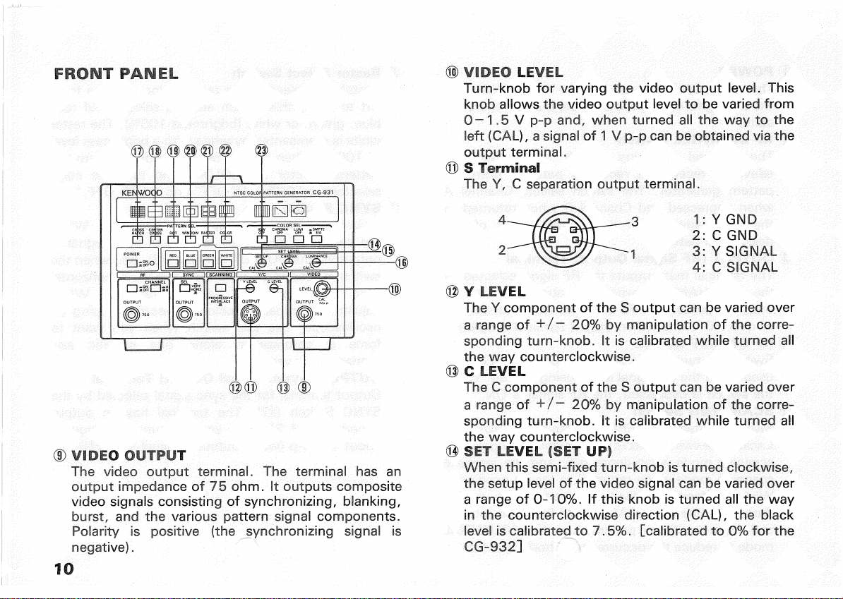
•S
output
isprovidedasstandardequipment,andY+
SandC outputscanalsobeobtained
from
theBNC
terminalontherearpanel.
•The
Y + S andC valuesoftheS
output
canbevaried
individually.
•The
setup,chrominance,andluminancelevelscan
befreelyset,anda CALisprovidedtomakethe
device
convenientforuseinoperationssuchasthe
adjustmentandrepairofcolortelevisionreceivers
andthelike.
•Throughuseofred,blue,green,andwhiterasters,
thedeviceenables
purity
confirmation,and
investigationandadjustmentofwhitebalance.
•The
deviceenablesrasteralignmentandinvestigation
andadjustmentofconvergencesbyuseofcenter
cross
anddotpatterns.
•The
deviceenablesevaluationofhigh-voltage
sta-
bility
viawindowpatterns.
•The
deviceisprovided
with
a 75ohmvideo
output
forvideocomponentsandalltypesofTVmonitors,
anda 75ohmRF
output
fortelevisionreceivers.
•To
facilitateobservationofthevariousTVreceiver
wave
formsviaoscilloscoverticalandhorizontal
4
synchronizingsignalscanbeobtained.
•The
device'ssynchronizingsignalincludesanequal-
izingpulse,andthedeviceisphase-lockedonthe
sub-carrier
wavefrequency.
•
In
addition
tointerlacedscanning,thedeviceallows
switchovertosequentialscanningmode,thereby
enablinga reductioninstripingflickerandsimplifying
relatedinvestigationandadjustmentprocedures.
•
Remote
controllablemodelsarealsoavailablewhich
enable
remoteswitchingofallpatternoptionsusing
the
RT-62
remotecontroller.