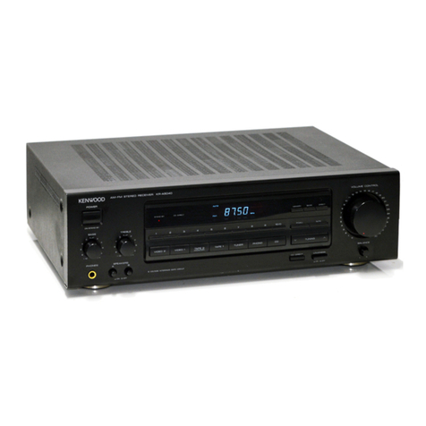
Kenwood Nine GX User manual

AM-FM
STEREO
RECEIVER
model
Nine
G
X
INSTRUCTION
MANUAL
Poe
very
SF
Ge
!
4.
D4
7.
’
*
KENWOOD
PLT
|

INTRODUCTION
The
purpose
of
this
manual
is
to
acquaint
you
with
the
operating
features
of
this
receiver.
You
will
notice
that
in
every
detail
of
planning,
engineering,
styling,
operating
convenience,
and
adaptability,
we
have
sought
to
anticipate
your
needs
and
desires.
We
suggest
that
you
read
through
this
manual
carefully.
Knowing
how
to
set
up
the
receiver,
to
the
best
advantage,
will
enhance
your
listening
pleasure
right
from
the
start.
You
will
also
become
aware
of
the
ease
with
which
you
can
adjust
the
receiver
to
meet
your
special
re-
quirements.
SERIAL
NUMBER
Record
your
SERIAL
NUMBER
on
the
spaces
designated
on
the
warranty
card.
You
will
find
the
serial
number
on
the
back
of
the
receiver.
AFTER
UNPACKING
After
unpacking,
we
recommend
that
you
inspect
the
receiver
for
any
possible
shipping
damage.
If
your
receiver
is
damaged
or
fails
to
operate,
notify
your
dealer
immediately.
If
your
receiver
was
shipped
to
you
directly,
notify
the
shipping
com-
pany
without
delay.
Only
the
consignee
(the
per-
son
or
company
receiving
the
receiver)
can
file
a
claim
against
the
carrier
for
shipping
damage.
We
recommend
that
you
retain
the
original
carton
and
packing
materials
to
prevent
any
damage
should
you
transport
or
ship
your
receiver
in
the
future.
INSTALLATION
PRECAUTIONS
a)
Avoid
locations
subject
to
direct
sunlight.
b)
Avoid
high
or
low
temperature
extremes.
c)
Keep
the
receiver
away
from
heat
radiating
source.
d)
Choose
stable
locations
with
as
little
vibra-
tion
and
dust
as
possible.
WARNING:
TO
PREVENT
FIRE
OR
SHOCK
HAZARD,
DO
NOT
EXPOSE
THIS
APPLIANCE
TO
RAIN
OR
MOISTURE
2
Model
Nine
GX
AC
VOLTAGE
SELECTION
This
receiver
operates
on
AC
120V,
220V
or
240V.
The
AC
Voltage
Selector
Switch
on
the
rear
panel
is
set
to
the
voltage
that
prevails
in
the
area
to
which
the
unit
is
shipped.
Before
connecting
the
power
cord
to
your
AC
outlet,
make
sure
that
the
setting
position
of
this
switch
matches
your
line
voltage.
If
not,
it
must
be
set
to
your
voltage
in
accordance
with
the
following
direction.
Note:
Our
warranty
does
not
cover
damage
caused
by
excessive
line
voltage
due
to
improper
setting
of
the
AC
Voltage
Selector
Switch.
Stopper
plate
Screw
Lever
AC
120V~
AC
220V~
ce
(6
DmD|e
AC
240V~
Position
©
() (]
CJ
+)
1.
Remove
screw
and
stopper
plate.
2.
Slide
lever
to
your
line
voltage.
3.
Lock
lever
with
stopper
plate
and
screw.
AC
VOLTAGE
SELECTOR
SWITCH
i

FEATURE
Srascusditueaareitieriiatretaads
Lea
Nata
eeadhae
Ulmane
eae
3
SYSTEM
CONNECTION
DIAGRAM
........csccsccscssceseessesesteseeseseees
4
SYSTEM
CONNECTIONS
o.scsciccscu;
osvessdtsnsctiaysesdivsseederotscunssby
tents
5
CONTROLS,
INDICATORS
AND
CONNECTORS...........0ccc0c00
8
PERATING
INSTRUCTI
WITHOUT
USI
CONTENTS
OLBYUNIT)
scenes
ensues
nanan
10
OPERATING
INSTRUCTIONS
(WITH
USING
DOLBY
UNIT).......
12
DOLBY
NR
MODE
CHART
........cccccccsccscsssssestesteseerestesesveees
16,
17
BLOCK
DIAGRAM,
:.5..0:cscisoscsscvessstestscsvonscsscsovaveessaseuneivsobsveoevts
18
SPECIFICATIONG..........
FEATURES
80
watts
per
channel,
min.
RMS
both
channels
driven
at
8
ohms
20
Hz
to
20,000
Hz
with
no
more
than
0.03%
total
harmonic
distortion.
Complete
Dolby*
facilities
for
all
program
source.
a)
Reception
of
Dolby
encoded
FM
pro-
gram.
b)
Taping
of
Dolby
encoded
FM
programs
with
simultaneous
decoding
and
monitoring.
c)
Dolby
encoding
when
taping
from
any
program
source,
Dolby
recording
of
any
Dolbyized
tape.
d)
Providing
the
Dolby
circuit
to
a
tape
deck
without
Dolby
NR.
.
Automatic
2-hour
Shut-off
Timer
Control.
.
Two
POWER/LINE
LEVEL
meters
for
check-
ing
power
output
level,
input
level
and
Calibration
level
of
Dolby
NR
system.
5.
Bass,
Mid
and
Treble’s
Triple
Tone
Controls
with
true
defeat
switch.
6.
Useful
push
bottom
type
input
SELECTORS.
7.
MIC
MIXING
system
for
adding
a
voice
of
your
own.
8.
High
sensitive,
low
distortion
FM_
station
reception.
9.
Many
useful
functions:
Dolby
NR
mode
selector,
400
Hz
oscillator
for
calibrating
the
Dolby
NR
system,
Recording
and
play
level
adjustor
for
Dolby
NR
system,
Power
meter
range
selector
3/150W,
Loudness
control,
Mode
selector
Mono/Stereo,
FM
Muting,
Subsonic
Filter,
High
Filter,
De-emphasis
selector
50/75
us
etc.
*
Dolby
and
the
double-D
symbol
are
trade
marks
of
Dolby
Laboratories.
Noise
reduction
system
is
manufactured
under
license
from
Dolby
Laboratories.
Model
Nine
GX
3

SYSTEM
CONNECTION
DIAGRAM
FM
OUTDOOR
FM
INDOOR
ANTENNA
AM
OUTDOOR
ANTENNA
DIRECTION
OF
ANTENNA
FM
Staton
Note:
If
the
75-ohm
antenna
terminals
are
used,
the
300-ohm
ones
should
not
be
used,
and
vice-versa.
ACIZOV~
/220V-
240V-V80/6
0H
o
(m0
e)
SWITCHED
UNSWITCHED
TOTAL
200W
MAX
200W
MAX
a
=
=
=
=
A+B
A+C,
or
A+B+C;
B~
162
SOyS4P
758
:
See
page
18.
To
AC
Outlet
Ox:
To
Bor
C
terminals
34IM
GNNOUS
oe
=
Right
TURNTABLE
A
TAPE
DECK
A
SPEAKER
SYSTEMS
SPEAKER
SYSTEMS
4
=
Model
Nine
GX

SYSTEM
CONNECTIONS
1.
One
Pair
of
Speakers
The
speakers
should
be
connected
to
the
A
terminals.
Only
the
corresponding
speaker
A
button
on
the
front
panel
should
then
be
pushed
to
activate
these
speakers.
2.
Two
Pairs
of
Speakers
Connect
the
two
pairs
of
speakers
to
the
A
and
B
speaker
terminals.
Push
A
button
for
A
and
B
button
for
B
speaker
system
response.
Push
both
A
and
B
buttons
in
if
you
wish
to
have
speaker
response
from
both
systems.
Note:
©
——————
SSS
No
response
will
be
obtained
if
both
B
and
C
buttons
are
pushed
in
when
only
one
speaker
is
thus
connected.
3.
Three
Pairs
of
Speakers
Connect
the
three
pairs
of
speakers
to
the
A,
B
and
C
speaker
terminals.
Push
in
only
the
corresponding
button
of
the
speaker
system
from
which
response
is
desired.
Note:
If
three
pairs
of
speakers
are
used
at
the
same
time,
a
speaker
system
must
have
an
impedance
of
8
ohms
or
more.
It
is
recommended
that
the
tips
of
the
speaker
cord
leads
be
soldered,
or
the
strands
of
individual
leads
be
twisted
together
to
eliminate
any
possibility
of
short-ircuit
in
the
speaker
connecting
network.
Refer
to
the
figure
below.
{Omm
===
a
Remove
insulation
from
wire
end.
mo
Twist
stranded
wire.
SPEAKER
LEAD
WIRES
Loosen
the
Insert
the
Tighten
the
screw
wire
screw
Correct
Speaker
Phasing
When
connecting
speakers
to
the
speaker
ter-
minals
of
the
unit,
be
sure
that
the
polarity
of
the
speakers
and
the
unit
terminals
correspond
properly;
that
is,
connect
the
positive
terminal
marked
(++)
of
the
speaker
to
the
positive
terminal
of
the
unit,
and
the
negative
terminal
marked
(—)
of
the
speaker
to
the
negative
terminal
of
the
unit.
Speakers
so
connected
to
the
unit
terminals
provide
proper
bass
response
in
sound
reproduc-
tion,
see
Fig.
A.
Improper
speaker
connection,
see
Fig.
B,
gives
poor
bass
response
in
sound
reproduction.
Connected
in
this
way,
the
bass
speaker
cones
are
moved
in
oposite
directions
reducing
bass
response.
Model
Nine
GX
5

SYSTEM
CONNECTIONS
FM
ANTENNAS
Since
FM
broadcast
signals
travel
along
a
straight
and
direct-line
path,
they
become
rather
weak
behind
hills
and
buildings
even
in
the
vicinity
of
a
transmitting
station.
FM
signals
also
become
weak
in
areas
distant
from
a
station
even
though
there
may
not
be
any
obstruction
to
the
direct-line
path
of
the
signal.
Therefore,
a
good
FM
antenna
should
be
installed
in
the
most
effective
manner
for
the
best
possible
FM
reception.
Mountain
a
Weakened
Signal
“
A
li
of
Gellected
Hall
MT
1
Strong
Signal
ave
DIRECT
WAVE
AND
REFLECTED
WAVE
FM
Indoor
Antenna
In
areas
close
to
the
transmitting
station,
the
supplied
T-type
antenna
may
suffice.
Spread
two
arms
of
the
antenna
horizontally
and
position
them
for
the
best
reception.-
listening
to
an
FM
station.
The
antenna
can
then
be
taped
to
a
wall
or
ceiling
and
must
not
be
rounded
nor
folded.
It
should
be
remembered,
however,
that
the
pickup
of
reflections
(similar
to
“ghosts”
on
TV)
will
result
in
poor
stereo
reception.
These
reflections
must
be
reduced
to
a
minimum,
either
by
careful
orientation
of
the
T-type
antenna
or,
if
this
will
not
eliminate
them,
by
using
a
more
directional
outdoor
antenna.
FM
T-TYPE
ANTENNA
TWIN
LEAD
(3002)
CONNECTION
6
Model
Nine
GX
FM
Outdoor
Antenna
In
areas
at
a
greater
distance
from
the
transmitting
station,
the
use
of
an
outdoor
antenna
is
highly
recommended.
It
is
available
in
various
types.
For
reception
of
stations
located
in
many
directions,
a
non-directional
type
antenna
will
offer
better
results.
When
using
a
directional
antenna,
always
orient
it
for
the
best
reception
of
the
desired
station.
The
correct
position
will
be
indicated
by
maximum
deflection
of
the
SIGNAL
meter
on
the
unit.
If
a
coaxial
FM
antenna
cable
(75
ohms)
is
to
be
connected,
the
connection
is
shown
as
follows.
Fold
back
the
Shield
net
wire.
Strip
the
coaxial
cable
as
shown
in
(A).
Loosen
the
screws
and
connect
the
cable
as
shown
in
(B).
Then
tighten
all
screws
for
a
connection
like
(C).
COAXIAL
CALBE
(752)
CONNECTION
AM
ANTENNAS
The
AM
ferrite
bar
antenna
incorporated
in
this
receiver
assures
satisfactory
reception
of
all
local
AM
stations.
Since
the
ferrite
bar
antenna
has
directional
purposes,
you
should
adjust
the
anten-
na
to
the
position
which
brings
in
the
strongest
signal.
In
fringe
areas
or
in
locations
surrounded
by
steel
frame
buildings
where
satisfactory
reception
cannot
be
obtained
with
the
ferrite
bar
antenna,
an
AM
outdoor
antenna
should
be
connected
to
the
AM
terminal.
Note:
To
prevent
any
possible
radio
interference,
keep
AC
power
cords
and
speaker
leads
away
as
far
as
possible
from
the
AM
ferrite
bar
antenna.

SYSTEM
CONNECTIONS
TURNTABLES
The
two
shielded
audio
cables
from
your
stereo
turntable
should
be
connected
to
the
phono
input
plugs.
Connect
the
left
channel
of
the
turntable
to
the
PHONO
1
[L]
input
jack,
and
the
right
channel
to
the
PHONO
1
[R]
input
jack.
If
an
additional
turntable
is
used
in
order
to
operate
two
turntables,
connect
the
left
channel
to
the
PHONO
2
[L]
input
jack,
and
the
right
channel
to
the
PHONO
2
[R]
input
jack.
And
either
case,
you
should
not
forget
to
connect
the
grounding
wire
to
the
receiver's
GND
terminal
to
eliminate
hum
noise.
TAPE
DECKS
Recording
A
tape
deck
can
be
connected
for
recording
as
follows.
Left
channel
input
of
the
tape
deck
to
the
TAPE
A
REC
[L]
jack.
Right
channel
input
of
the
tape
deck
to
the
TAPE
A
REC
[R]
jack.
Playback
A
tape
deck
can
be
connected
for
playback
as
follows.
Left
channel
output
of
the
tape
deck
to
the
TAPE
A
PLAY
[L]
jack.
Right
channel
output
of
the
tape
deck
to
the
TAPE
A
PLAY
[R]
jack.
DIN
CONNECTOR
(REC/PLAY)
If
your
tape
deck
is
equipped
with
a
DIN
connec-
tor,
connect
it
to
the
REC/PLAY
connector
with
a
DIN
cord.
The
DIN
connector
enables
recording
and
playback
with
this
single
cord.
However,
before
connecting
check
whether
the
impedances
at
the
DIN
connecting
terminals
of
the
receiver
and
the
tape
deck
are
equal.
If
they
are
not
equal,
use
RCA
pin
cords
to
ensure
correct
sound
quality.
Note:
©
——<—
—@—
SSF
When
the
tape
deck
is
connected
to
the
receiver
with
a
DIN
cord,
the
TAPE
B
PLAY
and
TAPE
B
REC
jacks
should
not
be
used.
AUX
(AUXILIARY)
High
level
AUX
input
jacks
are
for
miscellaneous
sources,
such
as
extra
tape
decks,
additional
tuners
and
other
external
components.
PRE
OUTPUT
4
PRE
OUTPUT-POWER
INPUT
jacks
By
utilizing
these
jacks
and
interconnecting
with
other
equipment
as
shown
in
Figure
below,
the
Model
Nine
GX
can
be
used
for
multi-channel
system.
Moreover,
by
simply
connecting
an
adap-
tor
to
these
jacks,
a
4-channel
reproduction
can
be
enjoyed.
In
such
a
case,
the
bridge
connecting
plugs
must
be
removed.
Use
of
the
multi-amplifier
system
is
as
follows.
1.
Remove
both
of
the
plugs
bridging
the
PRE
OUTPUT
and
POWER
INPUT
jacks.
2.
Connect
the
PRE
OUT
jacks
to
the
input
jacks
of
the
crossover
network.
3.
Connect
the
POWER
INPUT
jacks
to
the
out-
put
jacks
of
the
crossover
network.
Note:
For
detailed
instructions
on
connections,
etc.,
see
the
in-
struction
manual
supplied
with
the
adaptor.
POWER
AMP
POWER
AMP
POWER
INPUT
{(]
HIGH-
RANGE
CROSSOVER
NET
WORK
MID-RANGE
LOW-RANGE
PRE
AMP
POWER
AMP
AC
OUTLETS
The
AC
outlets
on
the
rear
panel
of
the
receiver
may
be
used
to
supply
power
to
other
components
such
as
a
turntable,
tape
deck,
etc.
1.
SWITCHED
outlets
These
outlets
are
controlled
by
the
POWER
switch
and
the
Timer
on
the
front
panel.
(The
total
capacity
is
200
watts
maximum.)
2.
UNSWITCHED
outlet
This
outlet
delivers
power
at
all
times.
(The
capacity
is
200
watts
maximum.)
Note:
Never
connect
any
equipment
whose
power
consumption
exceeds
the
capacity
of
each
outlet.
Model
Nine
GX
7

CONTROLS,
INDICATORS
AND
CONNECTORS
[1]
[2}[3]
[4]
[5
[6
ee
mode
Now
GX
it}
[2}
[13]
faa)
site
17)
[1]
SPEAKERS
A
—
Activates
speakers
connected
to
the
SPEAKER
A
ter-
minals
on
the
rear
panel.
B
—
Activates
speakers
connected
to
the
SPEAKER
B
ter-
minals
on
the
rear
panel.
C
—
Activates
speakers
connected
to
the
SPEAKER
C
ter-
minals
on
the
rear
panel.
For
private
listening
through
headphones,
release
all
the
SPEAKER
buttons.
[2]
POWER/LINE
LEVEL
switch
This
push
button
switches
the
meters
to
read
POWER
out-
put
or
LINE
signal
levels.
The
POWER/LINE
LEVEL
meters
indicate
the
power
output
level
when
the
switch
is
depress-
ed.
When
it
is
released,
the
meters
indicate
the
line
signal
level.
[3]
METER
range
switch
This
switch
allows
selection
of
meter
sensitivities
for
POWER
output.
Set
the
switch
to
either
the
3W
or
150W
setting
in
accordance
with
the
strength
of
the
power
output.
Note:
To
protect
the
meters
from
overswing,
make
it
a
rule
to
set
the
METER
range
switch
to
the
150W
position.
And
push
it
in
to
the
3W
position
for
a
more
sensitive
reading
only
when
the
meter
can
hardly
be
read
using
the
150W
switch
posi-
tion.
[a]
SPEAKER
indicator
The
lamps,
A,
B,
and
C,
light
to
show
which
SPEAKER
switches
are
engaged.
[5]
POWER/LINE
LEVEL
meters
POWER
—
When
the
POWER/LINE
LEVEL
switch
is
depressed,
the
meters
indicate
the
power
output
level.
8
Model
Nine
GX
18}
[19}
[20][21]
(22)
[23]
[2a
7}
[8]
9
].[10]
LINE
LEVEL
—
When
the
POWER/LINE
LEVEL
switch
is
released,
the
meters
indicate
the
line
signal
strength.
In
addition,
the
meters
are
to
be
used
as
Dolby
CAL
level
meters
when
the
400
Hz
CAL
switch
is
depress-
ed.
[6]
SIGNAL
meter
This
meter
indicates
the
strength
of
the
AM
or
FM
signals
received.
It
is
used
as
a
tuning
aid
for
both
AM
and
FMtun-
ing
and
very
useful
in
making
antenna
adjustments.
TUNING
meter
This
meter
gives
a
precise
indication
of
correct
FM
tuning.
Maximum
stereo
separation
and
minimum
distortion
are
Ob-
tained
when
the
receiver
is
tuned
to
center
the
pointer
on
the
meter
scale.
Indication
lamps
These
lamps
light
to
show
which
source
has
been
selected
by
the
SELECTOR
switches
and
which
mode
has
been
selected
by
the
function
switches.
[9]
TUNING
knob
AM
and
FM
stations
are
tuned
by
turning
this
knob.
SELECTOR
switches
AM
—
for
reception
of
AM
broadcasts.
FM
—
for
reception
of
FM
broadcasts.
PHONO
1
—
Audio
from
a
turntable
connected
to
the
PHONO
1
input
jacks.
PHONO
2
—
Audio
from
a
turntable
connected
to
the
PHONO
2
input
jacks.
AUX
—
Audio
from
a
source
connected
to
the
AUX
jaks.
[11]
POWER
switch
ON
—
turns
the
receiver
on.
OFF
—
turns
the
receiver
off.

CONTROLS,
INDICATORS
AND
CONNECTORS
[12]
PHONES
Insert
stereo
headphone
plugs
into
these
jacks.
[13]
TIMER
control
The
model
Nine
GX
is
equipped
with
a
TIMER
control
which
enables
the
set
to
be
switched
off
automatically
at
any
predetermined
time
within
two
hours
from
the
time
of
set-
ting.
If
the
predetermined
time
is
set
wrong
unintentionally,
for
example,
it
has
been
set
at
120
instead
of
60,
correction
can
be
made
by
turning
the
TIMER
control
counterclockwise
to
the
required
time
of
60.
The
TIMER
control
required
more
force
to
turn
counterclockwise
than
clockwise.
Note:§
——@—____________»>OSsSsSsSsSSssSF
When
the
TIMER
control
is
set
to
OFF,
the
AC
power
remains
off,
regardless
of
the
setting
of
the
POWER
switch.
Therefore,
the
TIMER
control
must
be
set
to
RESET
to
operate
the
receiver.
The
AC
convenience
outlet
on
the
rear
panel
marked
SWITCHED
200W
is
switched
by
the
POWER
switch
and
TIMER.
TRIPLE
TONE
CONTROL
ON
—
This
setting
activates
the
BASS,
MID,
and
TREBLE
controls.
OFF
—
This
setting
switches
in
a
bypass
circuit
to
provide
a
linear
frequency
response,
regardless
of
the
tone
con-
trol
settings.
[15]
FM
MUTING
switch
In
the
“depressed”
position,
muting
silences
interstation
noise
during
tuning.
To
receive
very
weak
stations,
stations
that
are
too
weak
to
overcome
the
muting
threshold,
disable
the
muting
by
pushing
the
switch
to
release.
FILTERS
SUBSONIC
—
Frequencies
below
18
Hz
are
attenuated
by
15
dB/octave.
Although
such
subsonic
frequencies
are
inaudible
to
the
human
ear,
they
can
cause,
inter-
modulation
distortions
and
even
damage
the
loudspeakers.
It
is
advisable
to
leave
the
switch
in
at
all
times,
even
if
no
record
rumble,
etc.
is
heard.
HIGH
—
Pressing
this
button
in
(latched)
reduces
signals
above
10
kHz
at
the
rate
of
6
dB
per
octave.
Press
this
button
in
to
lessen
the
effects
of
tape
hiss,
record
scratches,
etc.
Press
again
to
unlatch
(button
out)
in
all
other
cases.
TRIPLE
TONE
CONTROL
BASS
-—
Turn
clockwise
to
increase
bass
response,
counterclockwise
to
reduce
bass
response.
MID
—
Turn
clockwise
to
increase
mid-range
response,
counterclockwise
to
reduce
mid-range
response.
TREBLE
—
Turn
clockwise
to
increase
treble
response,
counterclockwise
to
reduce
treble
response.
LOUDNESS
control
The
LOUDNESS
control
compensates
for
a
natural
deficien-
cy
in
human
hearing,
the
human
ear
is
less
sensitive
to
bass
notes
at
low
volume
levels.
Use
the
LOUDNESS
control
to
give
the
best
bass
response
at
normal
listening
levels.
In
the
OFF
position
response
is
flat.
Use
this
setting
for
loud
listening
levels.
BALANCE
control
This
control
permits
balancing
of
left
and
right
channels
when
an
imbalance
exists
in
the
sound
source,
or
to
correct
an
acoustic
imbalance
due
to
room
conditions.
Turn
it
to
the
left,
from
the
zero
position,
to
boost
the
left
channel;
turn
it
to
the
right
from
zero
to
raise
the
level
for
the
right
channel.
MONO
switch
The
left
and
right
channel
signals
are
mixed
together
and
can
be
heard
from
both
speakers.
[21]
400
Hz
CAL
switch
This
is
used
for
calibration
of
the
record
input
level
of
a
tape
deck.
When
the
switch
is
depressed,
the
built-in
oscillator
Operates
and
a
sine
wave
signal
is
applied
to
the
TAPE
A
REC
jacks.
The
calibration
level
is
displayed
on
the
POWER/LINE
LEVEL
meters.
[22]
VOLUME
control
This
control
adjusts
left-
and
right-channel
volume
simultaneously.
Set
it
for
the
desired
listening
level.
[23]
NR
MODE
switch
OFF
—
This
position
is
for
operation
without
using
the
Dolby
unit.
ON
—
This
position
is
for
operation
with
using
the
Dolby
unit.
PLAY
for
playback
a
Dolbyized
recording
from
an
in-
coming
non-Dolbyized
signal.
Further
details
on
pages
16
and
17.
TAPE
MONITOR
switch
Switch
positions
and
functions
are
as
follows.
SOURCE
—
The
source
signal
is
heard.
A
—
For
monitoring
a
recording
or
for
playback
on
a
tape
deck
connected
to
the
TAPE
A
jacks.
B
—
For
monitoring
a
recording
or
for
playback
on
a
tape
deck
connected
to
the
TAPE
B
jacks.
[25]
DOLBY
LEVEL
control
PLAY
CAL
A
TAPE
—
These
knobs
control
the
playback
outputs
from
a
tape
deck
to
the
proper
Dolby
level.
REC
LEVEL
—
These knobs
control
the
record
level
of
the
signals
to
be
recorded
through
the
Dolby
unit.
Adjust
the
knobs
so
that
the
LINE
LEVEL
Meter
Pointer
remains
within
the
CAL
zone
of
the
POWER/LINE
LEVEL
Meter
and
the
tape
deck’s
VU
meters
indicate
“OVU".
MIC
MIXING
and
MIC
input
MIC
MIXING
permits
mixing
of
a
signal
from
the
mono
microphone
input
jack
with
the
desired
source
selected
with
the
SELECTOR
switch.
To
activate
MIC
MIXING,
pull
the
knob
and
turn
clockwise.
When
microphone
sound
is
not
required,
turn
the
MIC
MIXING
LEVEL
control
fully
counterclockwise
and
switch
off
by
pushing
in.
Further
details
on
page
11.
Model
Nine
GX
9

OPERATING
INSTRUCTIONS
(WITHOUT
USING
DOLBY
UNIT)
AM-FM
RECEPTION
Set
the
SELECTOR
switch
to
AM
or
FM.
2.
Set
the
MODE
switch
to
STEREO
(OFF)
and
the
TAPE
MONITOR
switch
to
SOURCE.
3.
Adjust
the
VOLUME
control
to
the
desired
listening
level.
4.
Use
the
TRIPLE
TONE
CONTROLS,
FILTER
and
LOUDNESS
controls
to
adjust
sound
as
desired
and
to
match
the
acoustic
conditions
of
your
room.
—_
TURNTABLE
OPERATION
1.
Two
pairs
of
phono
input
jacks,
PHONO
1
and
PHONO
2,
are
provided
to
enable
connections
to
two
turntables.
To
reproduce
the
output
of
the
turntable
connected
to
PHONO
1
jacks,
set
the
SELECTOR
switch
to
PHONO
1.
To
reproduce
the
output
of
the
turntable
con-
nected
to
PHONO
2
jacks,
set
the
SELECTOR
switch
to
PHONO
2.
2.
Set
the
MODE
switch
to
STEREO
(OFF)
and
the
TAPE
MONITOR
switch
to
SOURCE.
3.
Use
the
TRIPLE
TONE
CONTROLS,
FILTER
and
LOUDNESS
controls
to
adjust
the
sound
to
your
preference
and
to
the
acoustic
con-
ditions
of
your
room.
TAPE
DECK
OPERATION
Tape
Monitoring
If
you
use
the
receiver
with
3-head
type
tape
decks,
you
can
check
the
sound
quality
of
the
recording
being
made
momentarily
by
comparing
the
recorded
signal
with
the
source
signal
as
follows.
Set
the
TAPE
MONITOR
switch
to
A
(or
B)
to
monitor
the
recorded
sound.
Set
the
TAPE
MONITOR
switch
to
SOURCE
to
monitor
the
source
signal
before
recording.
10
=
Model
Nine
GX
When
Recording
with
One
Tape
Deck
Connect
the
tape
deck
to
either
TAPE
A
jacks
or
TAPE
B
jacks
on
the
rear
panel.
Recording
1.
Set
the
SELECTOR
switch
to
the
desired
program
source.
Set
the
TAPE
MONITOR
switch
to
SOURCE.
To
monitor
the
recording,
set
the
TAPE
MONITOR
switch
to
A
or
B,
whichever
side
the
tape
deck
is
connected.
2.
Recording
level
should
be
adjusted
with
the
volume
contro!
of
your
tape
deck.
3.
Recording
is
not
affected
by
the
VOLUME,
TRIPLE
TONE
CONTROLS,
FILTER,
LOUDNESS,
etc.,
controls
of
the
receiver.
When
Recording
with
Two
Tape
Decks
Connect
one
tape
deck
to
TAPE
A
jacks
and
the
other
to
TAPE
B
jacks
on
the
rear
panel.
Recording
1.
Set
the
SELECTOR
switch
to
the
desired
program
source.
2.
Set
the
TAPE
MONITOR
switch
to
SOURCE.
3.
Recordings
can
now
be
made
into
both
tape
decks
simultaneously.
To
monitor
these
recordings,
use
the
TAPE
MONITOR
switch
as
follows.
Set
it
to
A
to
monitor
the
recording
being
made
with
the
tape
deck
connected
to
TAPE
A
jacks.
Set
it
to
B
to
monitor
the
recording
being
made
in
the
tape
deck
connected
to
TAPE
B
jacks.
4.
Recording
levels
should
be
adjusted
exactly
as
mentioned
above
for
single
tape
deck
operation.
Playback
1.
The
SELECTOR
switch
can
be
in
any
position.
2.
Set
the
TAPE
MONITOR
switch
to
the
corresponding
position
(A
or
B).
3.
Adjust
volume
and
tonal
quality.

OPERATING
INSTRUCTIONS
(WITHOUT
USING
DOLBY
UNIT)
Tape-to-Tape
Dubbing
with
THROUGH
CIRCUIT
Tape
recordings
may
be
easily
duplicated
from
one
tape
deck
to
the
other
by
setting
the
NR
MODE
switch
to
OFF
A
>
B
or
OFF
B
>
A
as
follows:
1.
2.
3.
The
SELECTOR
switch
can
be
in
any
position.
Set
the
NR
MODE
switch
to
OFF
A>
B
when
it
is
desired
to
copy
recorded
material
on
the
tape
deck
A
for
re-recording
on
the
tape
deck
B.
Set
the
NR
MODE
switch
to
OFF
B®
A
when
_
it
is
desired
to
copy
a
recording
on
the
tape
deck
B
for
re-recording
on
the
tape
deck
A.
The
recording
can
be
monitored.
(If
the
TAPE
MONITOR
switch
is
set
to
SOURCE,
SOURCE
can
be
listened
to
even
during
the
tape-to-tape
dubbing.
This
is
thanks
to
the
THROUGH
CIRCUIT.)
Operate
both
tape
decks
simultaneously.
MIC
MIXING
WITH
SOURCE
PROGRAM
1.
Set
the
NR
MODE
switch
to
the
SOURCE
position
and
the
SELECTOR
switch
at
any
program
as
you
desired.
Then
turn
on
the
MIC
MIXING
by
pulling
its
knob.
TAPE
MONITOR
positions
are
as
follows.
SOURCE
...Source
program
mixed
with
MIC
input.
Aikgse.
eet
lots
Playback
sound
of
the
TAPE
DECK
A
(source
with
MIC).
Bockecienicciaes
Playback
sound
of
the
TAPE
DECK
B
(source
with
MIC).
2.
Set
the
NR
MODE
switch
to
the
REC-A
position
and
the
SELECTOR
switch
at
any
program
as
you
desired.
Then
turn
on
the
MIC
MIXING
by
pulling
its
knob.
TAPE
MONITOR
positions
are
as
follows.
SOURCE
...Source
program
mixed
with
MIC
input
through
the
Dolby.
Ascites
Playback
sound
of
the
TAPE
DECK
A
(Encoded
source
with
MIC
input).
Beek
sekis
Playback
sound
of
the
TAPE
DECK
B
(source
with
MIC).
Switch
|
(BSE,
|
Model
Nine
GX
11
;

OPERATING
INSTRUCTIONS
(WITH
USING
DOLBY
UNIT)
OUTLINE
OF
THE
DOLBY
NR
SYSTEM
The
basic
principle
of
the
Dolby
NR
system
is
as
follows.
During
the
recording
process,
all
low
level,
high
frequency
source
signals
above
midrange
—
the
area
where
noise
is
most
discernible
—
are
boosted
automatically
with
a
Dolby
compressor
circuit
before
being
put
on
tape.
During
playback,
the
Dolby
expander
circuit
automatically
reduces
these
boosted
signals
to
their
original
levels.
At
the
same
time,
the
tape
noise
introduced
during
the
recording
process
is
also
reduced
by
the
same
amount.
The
end
result
is
a
Significant
improvement
in
the
signal
to
noise
ratio.
This
means
that
tape
noise,
in
effect,
becomes
indiscernible
to
the
ear.
The
Model
Nine
GX
receiver
boosts
highest
fidelity
sound
reproduction
thanks
to
built-in
Dolby
NR
system
which
processes
signals
from
all
sound
sources.
This
means
that
FM
programs
can
be
of
equivalent
audio
quality
as
those
reproduced
from
your
“denoised”
tapes.
RECEPTION
OF
DOLBYIZED
FM
BROADCASTS
When
the
transmission
of
Dolbyized
FM
broadcasts
starts,
the
DOLBY
FM
switch
on
the
NR
MODE
must
be
selected
to
its
position
and
the
DOLBY
FM
decoder
operates
so
that
Dolbyized
FM
broadcasts
are
decoded
and
can
be
enjoyed.
At
this
time
the
SELECTOR
can
be
in
any
positions,
the
DOLBY
FM
switch
only
is
necessary
for
the
reception
of
Dolbyized
FM
broadcasts.
SETTING
THE
DOLBY
STANDARD
LEVEL
TO
RECORDING
AND
PLAYBACK
The
purpose
of
the
following
adjustments
is
to
achieve
the
proper
Dolby
levels
by
calibrating
the
recording
and
playback
signals
being
applied
to
the
Dolby
processors.
To
perform
this
adjustment,
the
Standard
Alignment
Tape
must
be
played
on
the
tape
deck
(or
recording
system)
connected
to
the
receiver.
However,
if
you
do
not
have
a
Standard
Alignment
Tape,
you
can
create
a
Dolby
Alignment
Tape
in
the
following
way
for
Dolby
recording
and
playback.
TO
CREATE
DOLBY
ALIGNMENT
TAPE
1.
Load
a
blank
tape
(or
insert
a
cassette)
on
the
tape
deck
connected
to
the
TAPE
A
jacks.
2.
Set
the
400
Hz
CAL
switch
to
ON
and
the
NR
MODE
switch
to
REC-A.
3.
Set
the
tape
deck’s
monitor
switch
to
its
source
position
and
adjust
the
tape
deck’s
input
level
control
so
that
it
indicates
a
recording
level
of
O
VU.
4.
In
this
condition,
record
the
signal
on
the
tape
for
about
one
minute.
You
have
now
created
a
Dolby
Alignment
Tape
for
the
adjustment
of
your
system.
5.
Now
turn
the
400
Hz
CAL
switch
and
NR
MODE
switch
OFF.
Please
refer
to
the
figure
below.
LINE
LEVEL
METER
UONESS
MONO
=
400Hz
CAL
SELECTOR
PHONO
|
PHONO
2
aa
12
Model
Nine
GX
66006
NR
MODE
lice
UR
A
APLAY
<A
Peary
ay
C.
OovBy
source
t
PR
TABeS
i
OorRe
OR
NR
MODE
POSITION
FOR
CREATING
DOLBY
ALIGNMENT
TAPE
OO
@
::.
“ON”
COLAY
SYSTEM
O.

OPERATING
INSTRUCTIONS
(WITH
USING
DOLBY
UNIT)
This
Dolby
Alignment
Tape
can
be
used
to
adjust
the
Dolby
recording
characteristics
of
your
receiver
and
the
tape
deck
or
recording
system
with
which
it
will
be
used.
Note:,§
————__—_
A
home
made
Dolby
Alignment
Tape
is
a
second
best
alter-
native
to
using
a
real
Dolby
Standard
Alignment
Tape.
However,
to
adjust
your
system
more
accurately
to
the
Dolby
standard
level,
a
Dolby
Standard
Alignment
Tape
is
available
from
Kenwood.
Contact
the
following
office,
specifying
the
model
of
the
tape
required.
Dolby
Standard
Alignment
Tape
Model
KST-11.....
for
Cassette
Tape
Deck
Model
KST-12.....
for
Open-Reel
Tape
Deck
TRIO-KENWOOD
CORPORATION
c/o
Higashiyama
Bldg.
7th
floor
1-2,
1-Chome,
Higashiyama
Meguro-ku,
Tokyo
153
Japan
PROCEDURE
FOR
PLAYBACK
CALIBRATION
1.
Connect
a
tape
deck
to
the
TAPE
A
jacks.
Set
the
Dolby
NR
MODE
switch
to
A
PLAY
(A
>
B).
3.
Set
the
POWER/LINE
LEVEL
switch
to
line
level.
4.
|fthe
tape
deck
has
a
monitor
switch,
set
it
to
tape
play.
5.
Load
the
Dolby
Alignment
Tape
on
the
tape
deck.
6.
Play
the
Dolby
Alignment
Tape.
7.
If
the
tape
deck
has
playback
level
controls,
adjust
these
so
that
the
tape
deck’s
VU
meters
indicate
O
VU.
8.
If
the
tape
deck
does
not
have
playback
level
controls,
proceed
to
Item
9.
If it
does
not
have
VU
meter,
set
the
level
controls
to
about
2/3
of
their
maximum.
9.
Adjust
the
PLAY
CAL
controls
(left
and
right)
so
that
the
LINE
LEVEL
meters
(left
and
right)
deflect
to
the
Dolby
CAL
mark.
10.
Now
that
Dolby
Playback
calibration
is
complete,
do
not
adjust
the
PLAY
CAL
controls
or
the
tape
deck’s
Playback
Level
controls.
Please
refer
to
the
figure
below.
LINE
LEVEL
METER
UDNESS
MONO)
400Hz
CAL
=
ON
B®
OFF
“OFF”
n”.CU!UC~«
En
SELECTOR
_*"""
PHONO
I
“PHONO2
AL
2
O00O00°0
NR
MODE
——
RR
TARE
MON
4
|
SOURCE
Ae
Be
®
»
Bea
A
PLAY
oz
ef
{A-B)
B,
REC
”
PLay
cat
!
DOLBY]
T:
-
a—t
SOURCE
!
e
EM.
I
|
5 5
=
OF
|
ie
ie
REC
LEVEL
NR
MODE
POSITION
FOR
PLAYBACK
CALIBRATION
Model
Nine
GX
13

OPERATING
INSTRUCTIONS
(WITH
USING
DOLBY
UNIT)
It
will
be
necessary
to
re-calibrate
the
Dolby
levels
as
described
in
the
following
manners:
1.
When
using
tapes
of
different
types
(Standard,
Low-Noise,
CrO2
etc.).
2.
When
changing
over
the
setting
of
the
tape
deck.
Otherwise,
the
controls
will
be
set
incorrectly.
To
avoid
making
mistakes
after
having
set
the
controls,
mark
their
positions
with
ribbon
tape
after
making
the
adjustment.
PROCEDURE
FOR
RECORD
CALIBRATION
Without
having
calibrated
the
playback
system,
the
recording
system
cannot
be
cablibrated,
so
first
calibrate
the
playback
system.
As_
for
playback
calibration,
calibrate
the
recording
system
with
a
tape
loaded
on
the
tape
deck
connected
to
the
TAPE
A
jacks.
Tape
Decks
1.
Load
a
blank
tape
or
insert
a
cassette
in
the
tape
deck.
Set
the
NR
MODE
switch
to
REC-A.
Set
the
400
Hz
CAL
switch
to
ON.
Set
the
tape
deck
to
the
recording
mode.
Adjust
the
tape
deck’s
input
level
controls
so
that
the
tape
deck’s
VU
meters
indicate
O
VU.
6.
Now
record
the
signal
on
the
tape
for
about
15
seconds.
7.
Set
the
400
Hz
CAL
switch
OFF
and
stop
the
tape
deck,
rewind
the
tape.
8.
Set
the
Dolby
NR
MODE
switch
to
A
PLAY
(A>
B)
and
the
POWER/LINE
LEVEL
switch
to
LINE
LEVEL.
9.
Set
the
tape
deck
to
playback.
10.
Observing
the
right
and
left
Level
Meters,
see
if
they
deflect
to
the
Dolby
CAL
Mark.
If
they
do,
the
calibration
is
correct.
11.
If
the
Level
meters
do
not
deflect
to
the
Dolby
CAL
Mark,
repeat
adjustments
of
the
tape
deck’s
recording
level
controls
so
that
the
receiver's
VU
meters
deflect
to
the
Dolby
CAL
Mark.
At
this
time,
do
not
adjust
the
tape
deck’s
playback
level
controls.
OWN
14
Model
Nine
GX
Tape
Decks
of
which
Record
and
Playback
Level
Controls
are
the
Same
This
type
of
tape
deck
is
such
that
one
control
must
be
used
to
calibrate
the
recording
and
playback
levels.
After
calibrating
the
recording
(playback)
level,
mark
the
position
of
the
knob.
Then
perform
the
adjustment
of
the
playback
(recording)
system
with
reference
to
the
marked
position.
Apart
from
this,
calibrate
in
the
same
way
as
with
a
two-head
deck.
TAPE
MON
A
SELECTOR
Switch
—§
REC
PLAY
REC
PLAY
A B
NR
MODE
POSITION
@

OPERATING
INSTRUCTIONS
(WITH
USING
DOLBY
UNIT)
This
concludes
the
adjustment
portion.
For
recording
and
playback,
perform
the
following
procedure:
Dolbyized
Recording
from
an
Incoming
‘Flat’
(Non-Dolbyized)
Signal
1.
Connect
a
tape
deck
to
the
TAPE
A
jacks
and
set
the
controls
to
the
positions
determined
in
CALIBRATION.
2.
Set
the
SELECTOR
switch
to
correspond
to
the
input
from
which
you
are
to
record
(AM,
FM,
PHONO,
AUX,
MIC
or
Tape
B).
3.
Set
the
NR
MODE
switch
to
REC-A
or
REC-B
PA.
4.
Adjust
the
REC
level
controls
so
that
the
level
meter
deflection
is
correct
(around
O
dB).
At
this
time,
do
not
adjust
the
tape
deck’s
Input
and
Output
Level
Controls.
All
adjustments
should
be
with
the
REC
level
control.
5.
Set
the
tape
deck
to
the
recording
mode.
400Hz
©
REC
OPER
ace).
REVEL
TAPE
MON
A
REC
PLAY
REC
PLAY
A
8
NR
MODE
POSITION
©,
@
Recording
Dolbyized
FM
Broadcasts
If
the
receiver
has
been
calibrated
to
make
Dolbyized
recordings,
set
the
NR
MODE
switch
on
its
DOLBY
FM
position
to
make
Dolbyized
recordings,
adjusting
the
recording
level
with
the
recording
level
controls
on
the
tape
deck.
After
decoding,
a
flat
signal
can
be
recorded
on
Tape
B.
To
Play
Back
Dolby
Tape
1.
If
the
tape
deck
connected
to
the
TAPE
A
jacks
has
not
been
calibrated,
do
this.
(See
page
13
“PLAYBACK
CALIBRATION”)
Set
the
TAPE
MON
switch
to
A.
Set
the
NR
MODE
switch
to
A
PLAY
(A
>
B).
Playback
using
the
tape
deck.
At
this
time,
if
there
is
a
tape
deck
connected
to
the
TAPE
B
jacks
in
the
normal
way,
decoded
signals
with
a
flat
frequency
characteristic
can
be
recorded.
ON
Dubbing
Dolby
Encoded
Tape
from
Tape
A
to
Tape
B
Dubbing
is
done
by
using
the
NR
MODE
switch.
When
recording
on
the
deck
connected
to
the.
TAPE
B
jacks
from
the
deck
connected
to
the
TAPE
A
jacks,
calibrated
by
adjusting
their
output
level
controls
in
conjunction
with
each
other.
(‘DOLBY
NR
MODE
CHART”
is
furnished
on
pages
16
and
17
for
your
ready
reference.)
Model
Nine
GX
15

DOLBY
NR
MODE
CHART
NR
MODE
eee
SOURCE
Ar
B
Brea
@2
6
BLOCK
DIAGRAM
Bold
line
shows
encorded
signal
DOLBY
FM
This
position
is
designed
for
only
the
DOLBY
FM
broadcasts.
And
the
recording
of
Dolby
FM
programs
are
available
to
TAPE
A
and
B.
TAPE
A
Encoded
signal
TAPE
B
Decoded
signal
The
positions
of
TAPE
MON
switch
are
as
follows.
SOURCE
...Decoded
Dolby
FM
Monitor
the
recording
of
TAPE
A
(Encoded)
Monitor
the
recording
of
TAPE
B
(Decoded)
The
Dolbyized
tape
of
the
TAPE
DECK
A
can
be
played
back
and
copied.
The
positions
of
TAPE
MON
switch
are
as
follows.
SOURCE
...Playback
sound
of
the
Dolbyized
tape
Sound
before
passing
through
the
Dolby
circuit
Copied
sound
Selector
[PLay
Switch
1
CA
The
signal
does
not
pass
through
the
Dolby
circuit
with
the
switch
set
to
this
position.
The
positions
of
TAPE
MON
switch
are
as
follows.
SOURCE
...Sound
selected
by
the
SELECTOR
switch
can
be
listened
to
while
dubbing
from
A
to
B
at
SOURCE.
Playback
sound
of
the
TAPE
DECK
A
Playback
sound
of
the
TAPE
DECK
B
16
Model
Nine
GX
When
the
Dolby
circuit
or
the
dubbing
circuit
is
not
used,
set
the
switch
to
this
position
(usual
position).

DOLBY
NR
MODE
CHART
The
signal
does
not
pass
through
the
Dolby
circuit
with
the
switch
set
to
this
position.
The
positions
of
TAPE
MON
switch
are
as
follows:
SOURCE
...Sound
selected
by
the
SELECTOR
switch
can
be
listened
to
while
dubbing
from
B
to
A
at
SOURCE.
Playback
sound
of
the
TAPE
DECK
A
Playback
sound
of
the
TAPE
DECK
B
When
modifying
the
Non-Dolbyized
tape
to
the
Dolbyized
tape,
set
the
switch
to
this
position.
The
played
back
signal
on
the
TAPE
DECK
B
passes
through
the
Dolby
circuit,
to
be
recorded
on
the
TAPE
DECK
A.
When
recording
through
the
Dolby
circuit,
set
the
switch
to
this
position.
The
positions
of
TAPE
MON
switch
are
as
follows.
SOURCE...Sound
selected
by
the
SELECTOR
switch
can
be
listened
to.
Encoded
sound
on
the
tape
A
can
be
monitored.
Recorded
sound
on
the
tape
B
can
be
monitored.
The
tape
A
is
the
only
tape
that
can
be
Dolby-recorded.
CAUTION
If
the
receiver's
built-in
Dolby
system
is
to
be
used,
adaptors
to
improve
sound
reproduction
(Reverberation
unit,
Dynamic
ex-
pander,
Graphic
equalizer,
Active
equalizer
etc.)
should
be
connected
to
the
PRE
OUTPUT
and
POWER
INPUT
jacks.
If
the
adaptors
are
connected
to
the
TAPE
jacks,
the
Dolby
system
should
not
be
used
since
this
will
spoil
the
Dolby
effect.
Be
sure
to
turn
off
the
AC
POWER
switch
before
connecting
adaptors
to
the
PRE
OUTPUT
and
POWER
INPUT
jacks.
Model
Nine
GX
17

BLOCK
DIAGRAM
Block
Diagram
S1
INPUT
SELECTOR
\j7
$2.
NR
MODE
$3.
TAPE
MONITOR
$4
400
Hz
CAL
S5
MODE
S6
LOUDNESS
$7
TRIPLE
TONE
CONTROL
ON
$8
METER
SELECTOR
$9
SPEAKERS
$10
FM
MUTING
$11.
POWER
RANGE
SIGNAL
TUNING
1
1]
il
:
'€
|
f
I
FERRITE
BAR
ANTENNA
2
Ke
x3
3
TRIPLE
()
$4
TONE
PRE
OUT©@)
©POWER
IN
Pre-amp
DOLBY{UNIT
20dB
amp
CONTROL
POWER
amp
PHONO
1
53
$5
QZ)
A
tho
SLRS
>
#4
Lam
aC
SIRS
LITHAS
Re
US)
4
VUU
a
CO—@
B
PHONO
2©
S2
=a
BALANCE
PUY
|
QP)
c
FM
pF
|
SUBSONIC/HIGH
DOLBY
VO|LUME
6)
__|
FILTER
4
S6
xs
STIQS)
PHONES
AUX
©
© ©
S7
Bal
1
MIC
amp
sa
TAPE
mic®
ee
£
Ese5
|
PHONES
—<—
|
vk
Lever
FM
DE-EMPHASIS
SWITCH
Prior
to
our
shipment,
this
switch
is
set
as
below
in
accordance
with
the
delivery
area.
Check
the
setting
position
before
operating
the
unit.
Im-
proper
setting
will
adversely
affect
the
high
fre-
quency
range.
Europe,
Oceania
and
South
Africa........
50us
OTH
OTS
iii
dasadedeeoia
eel
lem
sciecaea
Maceee
Seune
75us
NOTE:
As
for
the
Dolby
FM,
Set
the
NR
MODE
switch
to
DOLBY
FM
so
that
the
de-emphasis
of
“25us”
has
an
effect
on
Dolbyized
FM
programs,
regardiess
of
either
50us
or
75us
position
at
the
rear
pannel.
18
Model
Nine
Gx

SPECIFICATIONS
POWER
AMPLIFIER
SECTION
Power
Output
80
watts
per
channel
minimum
RMS,
both
channels
driven,
at
8
ohms
from
20
to
20,000
Hz
with
no
more
than
O
distortion.
Both
Channels
Driven
..................
Dynamic
Power
Output................
Total
Harmonic
Distortion............
Intermoduration
Distortion...........
(60
Hz:
7kHz
=
4:
1)
Power
Bandwidth
.....................5.
Frequency
Response
Signal
to
Noise
Ratio
...................
Damping
Factor..................
Input
Sensitivity/Impedance
..
Speaker
Impedance
.....................
.03%
total
harmonic
110
+
110W
40
at
1
kHz
280W
40
0.03%
at
rated
power
into
82
0.01%
at
1/2
rated
power
into
8
0.03%
at
rated
power
into
82
0.01%
at
1/2
rated
power
into
82
5
Hz
to
100,000
Hz
5
Hz
to
100,000
Hz
— 1.5
dB
115
dB
(short
circuited)
...
40
at
8
ohms
...
1,.0V/50
kQ
Accept
40
to
162
PRE
AMPLIFIER
SECTION
Input
Sensitivity/Impedance/Signal
to
Noise
Ratio
(IHF
A
curve)
PRON
sss
cc
soccnceckcsavedeaaveeseess
Maximum
Input
Level
for
Phono...
Frequency
Response
AUX
and
Tape..........0.....
cee
Tone
Control
BASS
eicceccciiieecccestestiyectfelivascer
Midivccn.
den
auans
aitneiuue.
TrODIG?®
sis
ladiici
ones
taans
Loudness
Control
(—
30
dB
Vol.)...
Subsonic
Filter
.................008
High
Filter
0.000...
eee
Output
Level/Impedance
Tape
REC
(Pin)
............0..0000.
Pre
Outicc
csi
hele
2.5
mV/50
kQ/80
dB
2.5
mV/50
kQ/80
dB
150
mV/50
kQ/110
dB
150
mV/50
kQ/110
dB
1.5
mV/10
kQ/70
dB
230
mV
(RMS),
T.H.D.
0.03%
at
1,000
Hz
RIAA
standard
30
Hz
to
20
kHz
+0.3
dB
10
Hz
to
40,000
Hz
— 1.0
dB
+12
dB
at
50
Hz
+12
dB
at
800Hz
+12
dB
at
15
kHz
+10
dB
at
100
Hz
—15
dB
at
18
Hz
—6
dB
at
10
kHz
A:
1580
mVv/1002
B:
150
mV/100Q
A:
30
mV/80
ko
B
:120
mV/80
kQ
1.0V/1
kQ
FM
TUNER
SECTION
Usable
Sensitivity
..............00..0.0.
10.3
dBf
(1.8
nV)
50
dB
Quieting
Sensitivity
14.7
dBf
(3.0
nV)
37.2
dBf
(40
nV)
Frequency
Response....................
30
Hz
to
15,000
Hz
+
0,5,
—1,.0dB
Capture
Ratio
....................000000.
1.0dB
Alternate
Channel
Selectivity
.......
75
dB
Spurious
Response
Ratio
.............
85
dB
Image
Response
Ratio
.................
60
dB
IF
Response
Ratio........................
75
dB
AM
Suppression
Ratio
at
G5dBE
sleigh
faceted:
65
dB
Stereo
Separation........................
48 dB
at
1,000
Hz
35 dB
at
50
Hz
to
15,000
Hz
Sub
Carrier
Product
Rejection
......
46
dB
Antenna
Impedance.....................
3002
balanced
and
752
unbalanced
FM
Frequency
Range
...................
88
MHz
to
108
MHz
AM
TUNER
SECTION
Usable
Sensitivity
.......................
20
nV
Signal
to
Noise
Ratio
...................
50 dB
Image
Rejection...
55
dB
Selectivity...
ees
30
dB
IF
Rejection
......0.00.....
eee
30
dB
Total
Harmonic
Distortion............
0.5%
GENERAL
Power
Requirement
.....................
50/60
Hz,
110-120/
220-240V
Power
Consumption
....................
550
watts
at
full
power
A.C.
Outlet
0...
eceeeeee
Switched
2,
Unswitched
1.
Dimensions
W..............0000008.
624
mm__,{24-9/16")
He
casigitasevsacsseeiints
206
mm__(8-1/8")
Di
ticareeatead
460
mm__(18-1/8")
Weight.
i0..0i5
2c.
lied
ceicescies
19.8
kg
(43.5
Ib)
(Gross)........
cece
24.3
kg
(53.6
Ib)
NOTE:
Kenwood
follows
a
policy
of
continuous
advancements
in
develop-
ment.
For
this
reason
specifications
may
be
changed
without
notice.
Model
Nine
GX
19
Other Kenwood Stereo Receiver manuals

Kenwood
Kenwood KRC-444D User manual

Kenwood
Kenwood Sovereign VR-5080 User manual

Kenwood
Kenwood VR-716A Quick start guide

Kenwood
Kenwood KR-A5040 User manual

Kenwood
Kenwood KRF-V5010 User manual

Kenwood
Kenwood KR-1000B User manual

Kenwood
Kenwood KR-V6040 User manual

Kenwood
Kenwood KR-A30 User manual

Kenwood
Kenwood KR-A3070 User manual

Kenwood
Kenwood KR-A4030 User manual
Kenwood
Kenwood VR-510 User manual

Kenwood
Kenwood KR-V126R User manual

Kenwood
Kenwood KRX-593 User manual
Kenwood
Kenwood KR-300HT User manual

Kenwood
Kenwood KRF-X9090D User manual

Kenwood
Kenwood KR-794 User manual

Kenwood
Kenwood 103AR User manual

Kenwood
Kenwood KRF-V7771D User manual

Kenwood
Kenwood DVR-6200 User manual

Kenwood
Kenwood VRS-6200 User manual