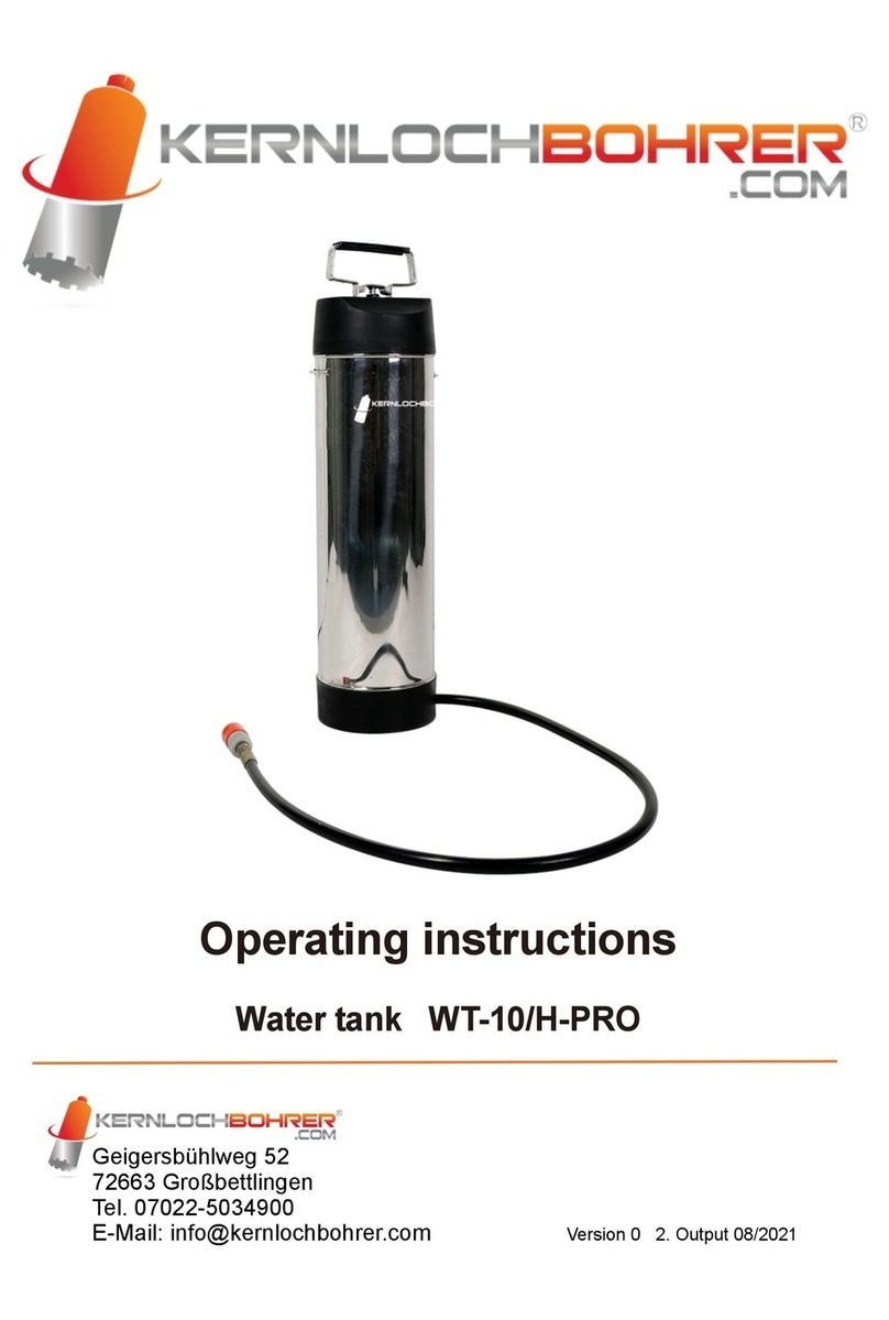
Kernlochbohrer WT-35/P-PRO User manual

Operating instructions
Water tank WT-35/P-PRO
Kernlochbohrer GmbH
Geigersbühlweg 52
72663 Großbettlingen
Phone: 07022-5034900
Email: info@kernlochbohrer.com Version 1 2. Output 05/2023

Content
Introduction 3
About this guide 3
Note 3
Explanation of symbols 4
Safety regulations 4
Before commissioning 7
Using the water tank 7
Battery level indicator 8
Transport 8
Cleaning and storage 8
Technical data 9
Troubleshooting 10
Environmental protection 11
Warranty 11
Exploded view 12
EC Declaration of Conformity 14
2

Introduction
Thank you for choosing the WT-35/P-PRO water tank from Kernlochbohrer GmbH.
This is a high-quality product based on state-of-the-art technology. We hope that
this device is to your satisfaction and meets your expectations. We are constantly
striving to improve our products in our product segment and will continue to supply
the market with new equipment.
Our company declines all responsibility in the event of violations of the operating
instructions that may lead to injuries or machine damage. In addition, all currently
applicable regulations of the Accident Prevention Regulations (UVV) and the
Employer's Liability Insurance Association (BG) must be observed.
About this guide
These operating instructions are for the model
WT-35/P-PRO
Check the machine model against the type plate.
Note
Read the entire instruction manual carefully before using the water tank. Special
attention should be paid to the section "Safety precautions".
Kernlochbohrer GmbH reserves the right to change the design and appearance of
the products and their operating instructions. Future changes to the operating
instructions will be made without prior notice.
3

Explanation of symbols
Warning of general danger. Failure to observe these safety precautions and
instructions may result in electric shock, fire and/or serious injury.
Safety regulations
❖Read all precautions before commissioning and keep the operating
instructions.
❖Please follow the operating instructions carefully, as failure to observe these
safety precautions and instructions may cause electric shock, fire and/or
serious injury.
1. Always check the charging cable and plug before recharging the battery. Only
have damage repaired by a specialist.
2. Only insert the plug into the socket when the water tank is switched off.
3. Do not use this tank to store flammable chemicals.
4. Always place the water tank on a flat, level floor and ensure that a strainer is
used when filling.
5. Never point the tank hose at a person or animal, whether the tank is switched
on or not.
6. This appliance is not intended for use by persons (including children) with
reduced physical, sensory or mental capabilities, or lack of experience and/or
knowledge, unless they have been given supervision or instruction concerning
use of the appliance by a person responsible for their safety. Children should be
supervised to ensure that they do not play with the appliance.
4

7. If the mains connector is damaged, the unit must no longer be charged.
8. Please ensure that the mains connection cable is not damaged by being driven
over, squeezed, tugged and the like.
9. Couplings of mains connection or appliance connection cables must be at least
splash-proof.
10. The unit must be connected to a line protected by a circuit breaker or a fuse
with the minimum current rating of 16A.
11. Do not operate the unit including accessories if: the unit shows visible damage
(cracks/breaks), the mains connection cable is defective or shows cracks or
ageing, there is suspicion of an invisible defect (after a fall).
12. No liability is accepted for any damage caused by misuse, improper operation
or improper repair.
13. There is a risk of electric shock if the appliance earth conductor is not
connected properly. Contact a certified electrician according to VDE or our
customer service if you are in doubt whether the socket is properly earthed. Do
not modify the plug supplied with the appliance. If it does not fit into the socket.
Have a suitable socket installed by a certified electrician according to VDE.
14. Note that the voltage must not exceed +/-5% of the nominal voltage. Higher
voltages can cause irreparable damage. Note that higher voltage peaks are not
generated when charging the water tank via a generator.
15. Do not charge the battery with a damaged charging cable or plug. If the charger
is not working properly, has been dropped or damaged, is outdoors or has fallen
into water. Make sure it is repaired by a qualified person.
5

16. Do not pull or carry the cable, use the cable as a handle, close a door on the
cable or pull the cable around sharp edges or corners. Do not run over the
cable. Keep the cable away from hot surfaces.
17. Do not pull the plug out of the socket by the cable. Do not hold the plug by the
cable to unplug it.
18. Do not handle the charging plug or the unit with wet hands.
19. Check the cable and plug regularly for damage. If the charging cable is
damaged, it must be replaced by a certified electrician according to VDE to
avoid danger.
20. Do not expose the water tank to precipitation.
21. Only allow trained personnel to operate the water tank.
22. Only use original spare parts and accessories for maintenance and repair.
23. Charge the accumulators in a dry and well-ventilated room. Escaping gases can
ignite in a confined space. Therefore, do not cover the ventilation when
charging.
24. Switch off the unit and disconnect the battery terminals before maintenance or
repair.
25. The installed motors and moving parts can cause injuries.
26. Battery acid can cause injuries to skin and eyes. Wear appropriate protective
clothing when handling the battery.
27. Keep electrical parts away from moisture.
28. Make sure that the main switch is in the "OFF" position before filling the water
tank.
29. Only use the machine when you are in full possession of your faculties.
6

Before commissioning
THE BATTERY MUST BE CHARGED 12 HOURS BEFORE FIRST USE!
It is important that you connect the battery correctly. Make sure that there is no
confusion here. Connect the red wire to the anode (+) and the black wire to the
cathode (-).
Fully charge the battery before or after each use. If the pointer points to the yellow
grid area, the battery must be recharged.
Charging the battery before it is completely discharged will not affect its life.
A completely discharged battery requires more than 10 hours of charging. At first
the charging indicator will show green, after more than 10 minutes of charging the
light will change to red, indicating that the battery is being charged. Once the
battery is fully charged, it will change back to green.
Using the water tank
Place the tank on a level surface when filling.
Install the outlet strainer and the inlet strainer in the correct position to protect the
pump and the nozzles from being clogged by impurities. Any impurities in the pump
can cause the water tank not to function properly.
The desired flow rate can be set on the valve to the desired range depending on
the contents of the water tank. We recommend reducing the water flow rate to a
minimum here. The lower the flow rate, the lower the power requirement, which
means that the battery can be used for a longer time. A high flow rate results in a
higher power requirement and thus reduces the battery's period of use before it has
to be recharged.
7

After filling the tank, tighten the cap on the filler neck clockwise. If you spill anything
during filling, wipe the tank with a cloth.
Battery level indicator
If the water tank's battery is low on power, the flow decreases, which means the
battery needs to be recharged.
Transport
When transporting your tank, make sure that the electricity is switched off. Always
place the tank in an upright position, protect the hose from sharp objects and never
transport your tank with harmful chemicals in it.
Cleaning and storage
After using the water tank, switch off the pump, fill some clean water into the tank.
Switch on the pump, let the pump run until the tank is empty. Make sure the pump,
hose and strainer are completely clean. Store your tank in a cool place.
8
Charger socket
Water hose
On/Off switch
Flow switch
Battery indicator

Make sure that the battery is fully charged after each use.
Keep the tank in a cool place that is inaccessible to children.
If you place the tank in a cold environment, you must empty all liquids in the tank.
Technical data
Capacity
35L
Battery
12V/17AH (Fuse:6A)
Maintenance free battery
Charger
Input 230V/50HZ
Automatic
Saturation
Output 12V/200MΩ
Pump
Pump model: FLO-2202A 12V2.6A
Flow rate: 4.0L/min.
Pressure switch cut-off at 4.8bar
Flow rate
5 levels adjustable
Display
Charge level indicator
Hose
6 metre outlet pressure hose
Tyres
Inflatable tyre, dimension: 8" Pressure: 3.0BAR
Weight
G.W: 22kg; N.W: 19kg
Dimension
43.5 x 36 x 89cm
9

Troubleshooting
Problem
Cause
Solution
The pump does not run
although the unit is
switched on.
The power supply was
disconnected.
Reconnect the battery cable.
Battery is empty
Charge the battery.
Damaged power switch
Replace the power switch
The pump makes very loud
noises.
Loose screws
Tighten the screws.
The pump is leaking.
The pump hose connection has
come loose or is broken.
Check the pump hose
connection, reattach the
clamps or replace defective
parts.
Pumps start again and
again
Clutch clogged
Clean the coupling.
Coupling or O-ring defective
Replace coupling or O-ring.
Gasket incorrectly
installed
Insert the seal in the correct
position.
Strainer clogged
Clean the sieve completely.
The hose has come loose from
the unit.
Reinstall the hose on the
machine.
Weak battery
Charge the battery or replace
the battery.
Pumps start again and
again
Clutch clogged
Check the coupling, clean
or replace it.
Loose or worn water hose
Tighten the tube clip and nut.
Small parts in the valve
Clean the valve thoroughly.
Too little flow at the coupling
Adjust the flow rate.
10

Environmental protection
Raw material recovery instead of waste disposal!
To avoid transport damage, the unit must be delivered in sturdy packaging.
Packaging as well as the unit and accessories are made of recyclable materials.
The plastic parts of the unit are labelled according to the material. This enables
environmentally friendly, sorted disposal via the collection facilities offered.
Only for EU countries
Do not throw power tools in the household waste! According to the European
Directive 2012/19/EU on waste electrical and electronic equipment and its
implementation in national law, used power tools must be collected separately and
recycled in an environmentally sound manner.
Warranty
In accordance with our general terms and conditions of delivery, a warranty period
of 12 months applies for material defects in business transactions with companies
(proof by invoice or delivery note). Damage caused by natural wear and tear,
overloading or improper handling shall remain excluded from this. Damage caused
by material or manufacturer defects shall be remedied free of charge by repair or
replacement. Complaints can only be accepted if the device is sent to the supplier
unassembled.
11

Exploded view
12

No.
Item no.
Designation
Number
1
11E40101
Tan k
1
2
11E40102
Inlet filter
1
3
11E40103
Cover
1
4
11E40104
Cover gasket
1
5
11E40105
Outlet seal
1
6
11E40106
Outlet cover
1
7
11E40107
Pump
1
8
11E40108
Car
1
9
11E40109
Axis
1
10
11E40110
Wheel 200*50
2
11
11E40111
Circlip
4
12
11E40112
Setting
2
13
11E40113
Handle
1
14
11E40114
Pipe connector
4
15
11E40115
Rubber cover
2
16
11E40116
Battery
1
17
11E40117
Steel plate
1
18
11E40118
Measuring device
1
19
11E40119
Setting switch
1
20
11E40120
Mains switch
1
21
11E40121
Charging socket
1
22
11E40122
Hose connector
1
23
11E40123
Nut M14
1
24
11E40124
Potentiometer
1
25
11E40125
Protective cap
1
26
11E40126
Outlet
1
27
11E40127
Output filter
1
28
11E40128
Fuse 250V 6A
1
29
11E40129
Gardena connection
1
30
11E40130
Plastic angle
1
31
11E40131
Battery holder
2
32
11E40132
Pipe (tank)
1
33
11E40133
Pipe (outlet)
1
34
11E40134
Hookah
1
13

35
11E40135
Gardena adapter
1
36
11E40136
Seal
1
37
11E40137
Schlauch tauchen
4
38
11E40138
Cross screw M3.5*16
2
39
11E40139
Cylinder head screw M8*16
2
40
11E40140
Cylinder head screw M8*25
2
41
11E40141
Nut M8
2
42
11E40142
Nut M8
4
43
11E40143
Hexagon head screw M8*35
2
44
11E40144
Hexagon head screw M5*25
6
45
11E40145
Cross screw M5*12
7
46
11E40146
Washer Φ5mm
12
47
11E40147
Washer Φ6mm
4
48
11E40148
Phillips screw M5*16
4
49
11E40149
Charger
1
14

EC Declaration of Conformity
The manufacturer/marketer
Kernlochbohrer GmbH
Geigersbühlweg 52
72663 Großbettlingen
hereby declares that the following product
Product name: Water tank
Typ: WT-35/P-PRO
complies with all relevant provisions of the applied legal regulations (hereinafter) - including their
amendments in force at the time of the declaration. The sole responsibility for issuing this
declaration of conformity lies with the manufacturer. This declaration relates only to the machine in
the condition in which it was placed on the market; parts and/or interventions subsequently fitted
by the end user are not taken into account.
The following legislation was applied:
EMV-Richtlinie 2014/35/EU
The following harmonised standards were applied:
EN 60204-1:2006+A1:2009 Safety of machinery - Electrical equipment of machines - Part 1:
General requirements
Part 1: General requirements
EN ISO 19932-1:2013 Plant protection equipment - Portable equipment
Part 1: Safety and environmental requirements
Requirements
Name and address of the person authorised to compile the technical file:
Kernlochbohrer GmbH
Geigersbühlweg 52
72663 Großbettlingen
Location: Großbettlingen
Date: 17.05.2023
Guido Pillat, Chief Executive
15
Table of contents
Other Kernlochbohrer Water Heater manuals