Kess KESSUPS 92RT User manual
Manual_KESSUPS92RT_V3_ENG
Uninterruptible power supply
KESSUPS 92RT
1 to 6 kVA
User Manual

2KESS Power Solutions GmbH / www.kess.at / [email protected]
CONTENT
1. INTRODUCTION 4
1.1 CONTACT 4
2. SAFETY INFORMATION 5
2.1 USED ICONS 5
3. QUALITY ASSURANCE AND STANDARDS 6
3.1 FIRST ENVIRONMENT 7
3.2 SECOND ENVIRONMENT 7
3.3 ENVIRONMENT 7
4. MODELS 8
4.1 VIEW OF THE MODELS 8
4.2 OPERATING PRINCIPLES 10
4.3 UPS OPERATING MODES 11
4.4 SPECIFIC FEATURES 12
4.5 OPTIONAL SUPPLIES 13
5. INSTALLATION 14
5.1 DELIVERY 14
5.2 PACKAGING 14
5.3 CONTENT 15
5.4 STORAGE 16
5.5 TRANSPORT TO THE SITE 16
5.6 SITE AND CONSTRUCTION 17
5.6.1 ROTATION OF THE CONTROL PANEL WITH LCD MONITOR 17
5.6.2 VERTICAL MOUNTING (TOWER) 18
5.6.3 VERTICAL MOUNTING (TOWER) WITH BATTERY MODULE 18
5.6.4 MOUNTING IN A 19“ CABINET 19
5.6.5 MOUNTING IN A 19“ CABINET WITH BATTERY MODULES 20
6. CONNECTION OF THE DEVICE 20
6.1 BEFORE CONNECTING 20
6.2 BEFORE CONNECTING BATTERIES AND THEIR PROTECTIONS 22
6.3 CONNECTION ELEMENTS 23
6.4 INPUT CONNECTION 23
6.5 CONNECTION OF THE IEC CONNECTOR OR OUTPUT TERMINALS 25
6.6 CONNECTION OF THE LOADS FOR MODELS UP TO 3 KVA 25
6.7 CONNECTION OF THE LOADS FOR MODELS 4 TO 6 KVA 26
6.8 CONNECTION OF EXTERN BATTERIES (BATTERY MODULE) 26
6.9 CONNECTION OF THE INPUT EARTH TERMINAL AND THE EARTH
CONNECTION TERMINAL 28
6.10 TERMINALS FOR THE EPO 28
6.11 TERMINALS FOR THE DIGITAL INPUT AND OUTPUT TO THE RELAY
(ONLY MODELS > 3 KVA) 29
6.12 AUXILIARY CONTACTS FOR THE MANUAL BYPASS
(ONLY FOR MODELS > 3 KVA) 29
6.13 PARALLEL CONNECTION (ONLY FOR MODELS > 3 KVA) 30
6.14 COMMUNICATION PORT 32
6.15 SOFTWARE 33

3
7. OPERATION 34
7.1 BEFORE OPERATING THE DEVICE WITH CONNECTED LOADS 34
7.2 CHECKS BEFORE OPERATION 34
7.3 START-UP OF AN UPS WITH MAINS VOLTAGE 35
7.4 START-UP OF AN UPS WITHOUT MAINS VOLTAGE 35
7.5 SHUT-DOWN OF AN UPS WITH MAINS VOLTAGE 35
7.6 SHUT-DOWN OF AN UPS WITHOUT MAINS VOLTAGE 36
7.7 OPERATION OF A PARALLEL SYSTEM (ONLY 4 TO 6 KVA MODELS) 36
7.8 OPERATION OF AN UPS WITH A PARALLEL SYSTEM OR A SINGLE UPS
(MODELS 4 TO 6 KVA) 37
7.9 REPLACEMENT OF A FAULTY UPS IN A PARALLEL SYSTEM 38
8. CONTROL PANEL WITH LCD MONITOR 38
8.1 INFORMATION SHOWN ON THE DISPLAY 38
8.2 LCD MONITOR FOR MODELS UP TO 3 KVA 41
8.2.1 ACOUSTIC ALARMS 42
8.2.2 PARAMETERS FOR THE UPS CONFIGURATION 42
8.2.3 SETTINGS ON THE UPS DISPLAY 45
8.2.4 MEANINGS OF THE OPERATION MODE 48
8.2.5 ERRORS, FAULT CODES & WARNING 49
8.3 LCD MONITOR FOR MODELS 4 TO 6 KVA 51
8.3.1 ACOUSTIC ALARMS 52
8.3.2 PARAMETERS FOR THE UPS CONFIGURATION 53
8.3.3 DESCRIPTION OF THE UPS OPERATION MODES (4 TO 6 KVA) 54
8.3.4 ERRORS, FAULT CODES AND WARNINGS 55
9. MAINTENANCE, GARANTY AND SERVICE 56
9.1 MAINTENANCE OF THE BATTERY 56
9.2 INDICATIONS FOR INSTALLATION AND REPLACEMENT OF THE BATTERIES 57
9.3 TROUBLESHOOTING FOR THE UPS 58
9.3.1 TROUBLESHOOTING GUIDE FOR DEVICES UP TO 3 KVA 59
9.3.2 TROUBLESHOOTING GUIDE FOR DEVICES FROM 4 TO 6 KVA 60
9.4 WARRANTY CONDITIONS 61
9.4.1 EXCLUSIONS FROM THE WARRANTY 61
10. GENERAL TECHNICAL SPECIFICATIONS 61

4KESS Power Solutions GmbH / www.kess.at / [email protected]
1. INTRODUCTION
We thank you in advance for the trust placed in us. Read this instruction manual
carefully in order to familiarize yourself with its content, since the more you know
about the equipment the greater your level of safety will be. We remain at your
disposal for any additional information or questions.
The equipment described here is capable of causing signicant physical
damage in case of improper handling. For this reason its installation,
maintenance and/or repair must be carried out exclusively by qualied
personnel.
Although no effort has been spared to ensure that the information in this user
manual is complete and accurate, we are not responsible for the completeness
of contents and accuracy.
The images included in this document are for illustrative purposes and may not
represent exactly the parts of the equipment shown.
Following our policy of constant evolution, we reserve the right to modify the
characteristics, operations or actions described in this document without prior
notice.
Reproduction, copying, assignment to third parties, modication or translation
of this manual, in any form, without previous written authorization by our rm is
prohibited. Our rm reserves the exclusive property rights.
1.1 CONTACT
KESS Power Solutions GmbH
Horn
Gewerbestraße 6
3580 Horn
Austria
telephone: +43 720 895010-0
fax: +43 720 895010-20
e-Mail: [email protected]
internet: www.kess.at
UID-Nr: ATU67467323
commercial register: 383965 f
legal form: Gesellschaft mit beschränkter Haftung
place of jurisdiction: Handelsgericht Wien

5
2. SAFETY INFORMATION
Important documents are available for downloading on our website
www.kess.at.
Compliance with the „Safety Instructions“ is mandatory and the user is legally
responsible for compliance and enforcement.
Read the safety instructions carefully before carrying out any action on the
device relating to its installation or start-up, change of location, conguration or
handling of any kind.
2.1 USED ICONS
For more information mind the safety instructions.
The equipment is delivered properly labelled for the correct identication of
each of the parts, which together with the instructions described in this user
manual allows the operations of installation and commissioning to be performed
in a simple and orderly manner without having any doubts whatsoever.
Finally, once the equipment is installed and operating, it is recommended to
save the documentation downloaded from the website, CD-ROM or Pen Drive in
a safe and easy-to-access place, for any future queries or doubts that may arise.
The following terms are used interchangeably in the document to refer to:
• “KESSUPS 92RT, KESSUPS, 92RT, device or UPS.“ Depending on the context of
the phrase, it can refer either to the actual UPS itself or to the the UPS and the
batteries, regardless of whether it is all assembled in the same metal casing or
not.
• “Batteries or accumulators.” Group or set of elements that stores the ow of
electrons by electrochemical means.
• “Client, installer, operator or user.“ These are used interchangeably to refer to
the installer and/or operator who will carry out the corresponding actions, and
the same person may be responsible for carrying out the respective actions
when acting on behalf of, or in representation of, the same.

6KESS Power Solutions GmbH / www.kess.at / [email protected]
3.QUALITY ASSURANCE AND STANDARDS
The product KESSUPS 92RT is designed, manufactured and sold in accordance
with quality management standards. The CE marking indicates conformity with
EU norms and the following guidelines:
The manufacturer accepts no liability in the case of modication or intervention
on the device by the user.
WARNING! KESSUPS 92RT up to 3 kVA is a category C2 UPS. In a residential
environment, this product may cause radio interference. In this case the user
must take additional measures.
KESSUPS 92RT 4 to 6 kVA is a category C3 UPS. This is a product for commercial
and industrial application in a second environment. Installation restrictions or
additional measures may be necessary to avoid disturbances.
It is not appropriate to use this equipment in basic life support applications (BLS),
where a failure can render vital equipment out of service or signicantly affect
its safety or effectiveness. It is also not recommended in medical applications,
commercial transport, nuclear installations, or other applications or loads, where
a failure can lead to personal or material damages.
The EC declaration of the product is available to the customer on request.
• 2014/35/EU Low voltage safety.
• 2014/30/EU Electromagnetic Compatibility (EMC)
• 2011/65/EU Restriction of the use of hazardous substances in
electrical and electronic equipment (RoHS).
• EN-IEC 62040-1 Uninterruptible Power Supplies (UPS) part 1: General and
safety requirements for UPS used in user access areas
• EN-IEC 60950-1 Information technology equipment - safety. part 1:
General requirements.
• EN-IEC 62040-2 Uninterruptible Power Supplies (UPS) part 2: EMC
requirements.

7
3.1 FIRST ENVIRONMENT
Environment including residential, commercial and light industry installations,
directly connected, without intermediate transformers, to a low voltage public
power grid.
3.2 SECOND ENVIRONMENT
An environment that includes all commercial, light industrial and industrial
establishments that are not directly connected to a low voltage power grid
supplying buildings used for residential purposes.
3.3 ENVIRONMENT
This product has been designed according to ISO 14001 and complies with all
essential environmental regulations .
Recycling of the equipment at the end of its lifespan
When it comes to disposal, the producer feels obliged to work together with
authorized and regulatory companies, so that all components are recyled
correctly after their effective lifespan. (Therefore contact your distributor.)
Packaging
Mind the legal requirements and specic regulations of the country in which the
device is installed.
Batteries
Batteries pose a serious danger to our health and the environment. Their disposal
should be carried out in accordance with the laws in force.

8KESS Power Solutions GmbH / www.kess.at / [email protected]
4.MODELS
4.1 VIEW OF THE MODELS
Fig. 1 to Fig. 3 show the different devices. Please mind that our products are
constantly evolving and discrepancies or slight contradictions may arise. In case
of doubt the labelling on the equipment itself will always be representative .
The nameplate of the device shows all relevant values.
Models up to 3 kVA
Battery module for models 1 to 6 kVA
6 kVA models
Control panel with LCD monitor
Control panel with LCD monitor
Plastic front trim
Plastic front trim
Fig.1: Front view of the models 3 to 6 kVA and its battery modules

9
Models up to 1,5 kVA
Fan
Earth connection
Input connector for Modem /
ADSL / Fax
Output connector with protection
for Modem / ADSL / Fax
Port Com
USB
Port Com RS-232 Protective cover for
the smart slot
Connector for
external EPO
Connector for the external
battery module
IEC output connector, non
programmable for critical loads
IEC output connector, programmable for
disconnection and non-critical loads
IEC input connector of the
AC power
Output connector with protection
for Modem / ADSL / Fax Fan
Port Com
USB Connector for
external EPO
Connector for the
external battery
module
IEC output connector, programmable for
disconnection and non-critical loads
IEC input connector of
the AC power
IEC output connector, non
programmable for critical loads
Port Com RS-232
Earth connection
Input connector for Modem /
ADSL / Fax
Output connector with protection
for Modem / ADSL / Fax
Fan Input connector for
Modem / ADSL / Fax
Connector
for external
EPO
Earth connection
Port Com
USB
Protective cover
for the smart slot
Connector for the
external battery
module IEC output connector, programmable for
disconnection and non-critical loads
Port Com
RS-232
IEC output connector, non
programmable for critical
loads
IEC input connector of
the AC power
IEC output connector of
16 A power
Fan
Port Com
RS-232
Port Com
USB Protective cover
for the smart slot
Connector for the external
battery module
2 kVA model
3 kVA model
6 kVA model
Protective cover for
the smart slot
Connector
for external
EPO
Earth connection
Output / earth/ input
terminals
communication bus
for parallel systems
Current signal bus for
parallel systems
Auxiliary contact of
the manual bypass
10 KESS Power Solutions GmbH / www.kess.at / [email protected]
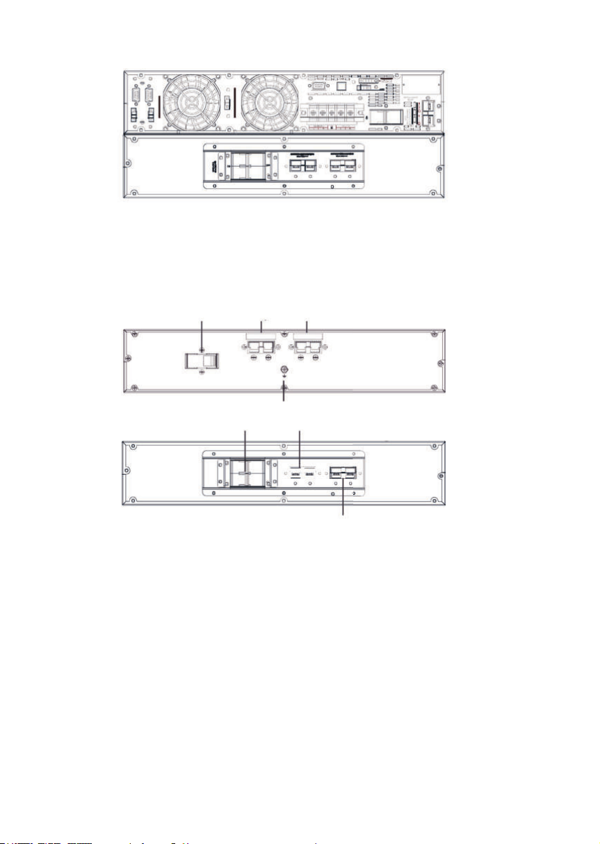
6 kVA model with battery module
Fig.2: Rear view oft the models 1 to 6 kVA
VDC-Schutz
Input connector for
battery module
Output connector for
battery module
Earth connection
Battery module for 1 to 3 kVA-device
Battery module for 6 kVA device
VDC protection battery module connector
Battery module
connector
Fig.3: Rear view of the battery module
4.2 OPERATING PRINCIPLES
This manual describes the installation and operation of the uninterruptible power
supply (UPS) KESSUPS 92RT as devices that can be independently operated or
connected in parallel (for models > 3 kVA).
The KESSUPS 92RT series ensures optimum protection of any critical load,
maintaining the supply voltage of the loads between the speci ed parameters
without interruption during failure, deterioration or uctuation of mains power,
and comes in a wide range of models (from 1 kVA to 6 kVA). Thus market-speci c
needs and wishes can be addressed in a more individual way.

11
Thanks to their PWM (pulse width modulation) and double-conversion
technology, the KESSUPS 92RT series is compact, silent and offers high
performance.
The double converter principle eliminates all mains power disturbances. A
rectier converts the AC current of the mains into DC current. It maintains the
optimum battery charge level and powers the inverter, which in turn, generates
a suitable AC sine-wave voltage for continuously powering the loads. In the case
of failure the batteries supply clean power to the inverter.
The design and construction of the KESSUPS 92RT series has been carried out in
accordance with international standards.
In addition, models with power ratings greater than 3 kVA can be expanded with
the connection of additional modules with the same power in parallel to obtain
N+X redundancy or an increase in the system‘s power.
This series has been designed to maximise the availability of critical loads and to
ensure that your business is protected from variations in the power distribution line
voltage, frequency, electrical noise, cuts and micro-cuts. This is the primary goal
of the KESSUPS 92RT series.
4.3 UPS OPERATING MODES
Normal mode
The device supplies output voltage from the inverter, mains power present with
correct input voltage and frequency.
Battery mode
The device runs with mains voltage or frequency out of range or without AC
input power, either due to mains failure or absence of cable connection,
supplying output voltage from the batteries.
Bypass mode
No matter the device is running or not, it supplies output voltage directly from
the AC mains.
With the inverter running, this operating mode may occur due to an overload,
blockage or inverter fault. The actions for each incident will be as follows:
Reduce the load connected to the output, unblock the device by resetting it
(stop it and start it again) and if the fault remains, contact the KESS service.
With the inverter shut down, the output supplies the main power directly through
the static bypass of the device, provided that it has AC input power.

12 KESS Power Solutions GmbH / www.kess.at / [email protected]
Frequent converter mode (CF)
Operating mode of the UPS as a frequency converter. In this mode, the static
bypass is disabled by the condition of disparate input and output frequencies.
Even if the LCD monitor shows a messages, it does not mean that the inverter
is operational. It is switched on by pressing the ‘ON’ button on the control
panel, see chapter 7.
4.4 SPECIFIC FEATURES
• True online with double-conversion technology and output frequency
separate from the mains.
• Output power factor 1. Pure sine waveform, suitable for almost all kinds of
loads.
• Input power factor > 0.99 and high overall performance (between 0,89 and
0,91 for models up to 3 kVA models and > 0,93 for higher power ratings).
Greater energy savings and lower user installation costs (wiring) are achived,
as well as low distortion of the input current, which reduces pollution in the
power supply network.
• Great adaptability to the worst conditions of the mains. Wide input voltage,
frequency and waveform ranges, thus avoiding excessive dependence on
limited battery power.
• Possibility of fast and easy backup extension by adding modules in rack
format. Each battery module has two connectors for easy connection to the
device and other identical modules.
• N+X redundant parallel connection to increase reliability and exibility in
power models > 3 kVA, with a maximum of 3 devices in parallel.
• Selectable high-performance mode (ECO MODE) > 0,95 to 0,99 depending on
the model. Financial savings for the users are possible.
• It is possible to start the device without mains power supply or discharged
battery. Be careful with this aspect because the greater the batteries are
discharged, the more the backup will be reduced.
• Intelligent battery management technology is very useful for extending the
lifespan of the accumulators and optimising the recharge times.
• Standard communication options via the RS232 serial port or USB port.
• Digital input for Start/Stop of the device and ‘Error or fault’ digital output in
models with power ratings > 3 kVA.
• Remote emergency power off control (EPO).
• Control panel with LCD monitor available on all models and LED indicators on
devices with power ratings > 3 kVA.
• Availability of optional connectable cards to improve the communication
capabilities.
• The device can be installed as a tower or rack using the attached supplies. The
control panel can be rotated.

13
4.5 OPTIONAL SUPPLIES
Isolation transformator
The isolation transformer provides galvanic isolation in order to completely
isolate the output from the input and/or change neutral mode. The placement
of an electrostatic screen between the primary and secondary windings of the
transformer provides a high level of electrical noise attenuation.
The isolation transformer can be physically placed at the input or output of the
UPS depending on the technical conditions of the whole system (device supply
voltage and/or load voltage, characteristics or their type, etc.).
In parallel systems, it is not possible to operate with independent transformers
for each UPS. In contrary, it is necessary to have a single common element for
the total adequate power. In any event, it will always be supplied as a
peripheral component external to the device itself in a separate box.
External maintenance bypass
The purpose of this option is to electrically isolate the device from the mains
and the critical loads without cutting the power to the latter. In this way,
maintenance or repair operations on the device can be carried out without
interruptions to the power supply of the protected system, while preventing
unnecessary hazards for the technical personnel.
Communication card
The UPS features a slot at the rear for inserting one of the following
communication cards:
• Integration using an SNMP-Adapter: Large computer systems based on LANs
and WANs that integrate servers in different operating systems must provide
the system manager with ease of control and administration. This facility is
obtained through an SNMP adapter. While the connection betwenn UPS
and SNMP is internal, the connection of the SNMP is made through a RJ45-10
base connector.
• Relay interface card: The UPS has an optional interface for relaycards
that provides digital signals in the form of potential-free contacts, with a
maximum applicable voltage and current of 240 V AC or 30 V DC and 1A. This
communication port enables a dialogue between the device and other
devices through the relays supplied in the terminal block (arranged on the
same card), with a single common terminal for all of them. From the factory, all
contacts are „normally open“ and can be changed one by one, as explained
in the information concerning the optional supplies. Please contact our KESS
Service for further information.

14 KESS Power Solutions GmbH / www.kess.at / [email protected]
Extendible guide bars for rack mounting
An extendible guide bar is optional available for all models. These bars allow the
19“ rack installation for any KESSUPS 92RT-device and any battery module.
5.INSTALLATION
Please mind our safety information. Non-compliance may lead to serious
accidents for people in direct contact or in the immediate vicinity, as well as
faults in the equipment and/or connected loads.
If not otherwise indicated, all actions, instructions, guidelines and notes are
applicable to the device, no matter they are part of a parallel system or not.
Pay attention to the chapters 2 and 5 concerning the safety information,
manual, storage, transport or installation of the device. Only use suitable means
of transportation to move the UPS in its packaging with a forklift or a lifting cart.
In any means, consider the technical data of the device as described in chapter
9.
5.1 DELIVERY
5.2 PACKAGING
To check the contents, it will be necessary to remove the packaging. Unpack in
the following way:
• Cut through the ribbons of the cardboard packaging.
• Remove the supplies (cable, mountings, etc.).
• Remove the device or the battery module from its packaging. Depending on
the devices weight the help of a second person or suitable mechanical aids
should be considered.
Check that the data on the labelling corresponds to your specic order. Once
the UPS is unpacked, check the previous data with those of the equipments
nameplate.
If there are any discrepancies, let us as soon as possible know. Therefore please
keep the manufactures number of the device and the reference number on the
delivery note in readiness.
Also check the packaging and that it has not suffered any mishaps during
transportation (packaging and impact indicator are in perfect condition).
Otherwise, follow the protocol indicated on the label attached to the impact
indicator.

15
• Remove the corner protector and the plastic cover. Keep the
packaging out of the reach of children.
• Check the device before continuing. If any failures occure, please contact the
KESS service.
• The devices packaging consists of a wooden pallet, cardboard,
polystyrene corners, polyethylene cover and strapping. All materials are
recyclable and the disposal must be carried out in accordance with current
laws. We reccomend to keep the packaging and use it again.
5.3 CONTENT
Devices 1 to 3 kVA:
• 1 UPS
• Quick start guide on paper
• 1 UPS communication cable
• 3 cables with IEC connectors for loads
• 1 cable for the devices AC power supply
• 2 metal pieces for the use as handles and screws for installing the unit in a rack
cabinet
• 4 plastic pieces for use as a base to facilitate the arrangement of the UPS as
a tower (vertical position)
Optional battery modules for UPS 1 to 3 kVA:
• 1 battery module
• 2 metal pieces for the use as handles and screws for installing the unit in a rack
cabinet
• 4 plastic pieces for use as a base to facilitate the arrangement of the UPS as
a tower (vertical position)
• 1 cable for connecting the battery module and an UPS or an other module
Devices 4 to 6 kVA:
• 1 UPS
• 2 metal pieces for the use as handles and screws for installing the unit in a rack
cabinet
• UPS connection cable
• USB-Kommunikationskabel
• 4 plastic pieces for use as a base to facilitate the arrangement of the UPS
as a tower (vertical position)
• 1 connection cable for the communication bus (Only useful for the connec-
tion of parallel devices).
• 1 cable for connecting the battery module and the UPS
Optional battery module for UPS 4 to 6 kVA:
• 1 battery module
• 2 metal pieces for the use as handles and screws for installing the unit in a rack
cabinet
• 2 plastic pieces for use as a base to facilitate the arrangement of the UPS as
a tower (vertical position)
• 1 cable for connecting the battery module and an UPS or an other module

16 KESS Power Solutions GmbH / www.kess.at / [email protected]
5.4 STORAGE
After receipt of the delivery it is advisable to repack the UPS till its nal
implementing to protect it against potential mechanical impacts, dust, mud, etc.
The device should be stored in a dry, ventilated room and protected from rain,
dust and water or chemical splashes. It is advisable to keep each device and
battery module in its original packaging, as it has been specically designed to
ensure maximum protection during transportation and storage.
For devices that contain Pb-Ca batteries, the indicated charging times must
be respected, otherwise the warranty may be invalidated.
After this period, connect the device to the mains together with the applicable
battery module. Start it according to the instructions described in this manual
and charge it for 12 hours.
In parallel systems, it is not necessary to interconnect the devices before battery
charging. Each of them can be treated independently to charge them.
Then shut the device down and disconnect it. Store the UPS and batteries in their
original packaging and note the new date for recharging the batteries.
Do not store the devices at places where the ambient temperature exceeds
50ºC or drops below -15ºC, as this may cause degradation of the electrical
characteristics of the batteries.
5.5 TRANSPORT TO THE SITE
It is recommended to transport the UPS with a forklift or suitable means of
transportation. Always mind the distance between both locations. When the
distance is great, it is recommended to transport the device in its packaging to
the installation site and then unpack it.
17
5.6 SITE AND CONSTRUCTION
All KESSUPS 92RT UPS are designed to be mounted as a tower (vertical) or rack
(horizontal) for installation in a 19“ cabinet. This applies for single as well as
parallel systems, whether a battery module is existing or not.
Follow the instructions indicated in this manual regarding the special features of
your device.
As example, Fig. 4 to 6 show illustrations of a device or a battery module. These
illustrations provide help and guidance in the following steps, but the instructions
are not intended to refer to a single model. Although the carried out actions are
in practice always the same for all of them.
For all instructions regarding the connections, refer to chapter 6.
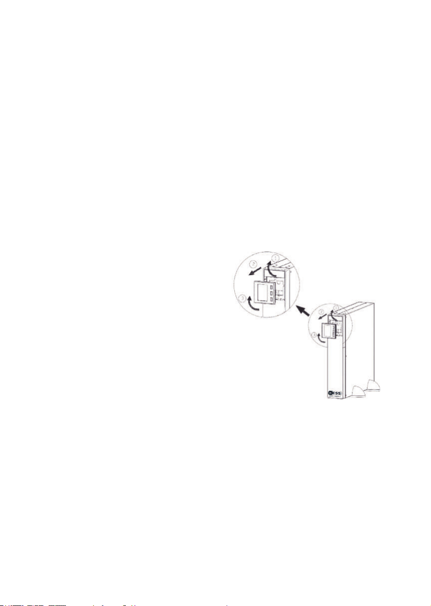
5.6.1 ROTATION OF THE CONTROL PANEL WITH LCD MONITOR
To facilitate reading the messages on the
display, it is possible to rotate the control
panel clockwise by 90º (see Fig. 4).
Proceed as follows:
Fig.4: Rotatable LCD monitor
• Insert your ngertips into the recesses of
the plastic housing around the display
and pull outwards.
• Rotate the control panel with LCD mo-
nitor 90º to the right and put it on its in-
itial position.

18 KESS Power Solutions GmbH / www.kess.at / [email protected]
5.6.2 VERTICAL MOUNTING (TOWER)
• Rotate the control panel according to chapter 5.6.1.
• Take the 4 pieces of plastic supplied with the device and join 2 pieces together
to obtain 2 feet bzw. bases.
• Place the UPS upright between the 2 feet at a distance of 70 mm (from each
end). See Fig. 5.
Fig.5: Vertical mounting (tower)
5.6.3 VERTICAL MOUNTING (TOWER) WITH BATTERY MODULE
• Rotate the LCD monitor.
• Take the 4 plastic pieces in angle form
(supplied with the UPS ) and the 2 angle
forms supplied with the battery modu-
le. Install them to obtain 2 bases to hold
the device and the battery module.
• Place the UPS and battery module up-
right between the 2 bases at a distance
of 70 mm from each end.
This paragraph refers only to devices with
a single battery module. For devices with
a greater number of battery modules
proceed in a similar way.
Fig.6: Vertical Mounting (tower) with battery
module
19
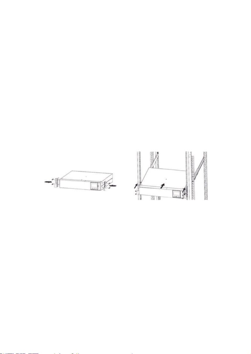
5.6.4 MOUNTING IN A 19“ CABINET
• Proceed as in g. 7 to install the device in a 19” cabinet.
• Use the supplied screws to x the 2 angle form adapters as handles on each
side of the UPS.
• To install the device in a rack cabinet, it is necessary to apply the lateral
internal guides as mounting. Alternatively, and on request, we can supply
universal slides as guides. These must be installed by the user. Mount the guides
at the required height, ensure the correct tightening of the xing screws and
the appropriate tting of the slides.
• Place the device onto the guides and insert it all the way to the back. It
depends on the device model and weight if it should be installed in the upper
or lower position. It is recommended that 2 people carry out the installation
operations.
• Fix the UPS to the cabinet frame using the screws supplied with the handles.
Fig.7: Mounting as a rack device in a 19“ cabinet

20 KESS Power Solutions GmbH / www.kess.at / [email protected]
• This paragraph refers only to devices with a single battery module. For devices
with a greater number of battery modules proceed in a similar way.
• Proceed as in Fig. 8 to install the device and its battery module in a 19”
cabinet.
• Use the supplied screws to x the 2 angle form adapters as handles on each
side of the UPS. Mind your hands. Repeat the same procedure for the battery
module.
• It is necessary to apply the lateral internal guides as mounting to install the
device, UPS or battery modules in a rack cabinet. Alternatively, and on
request, we can supply universal slides as guides. These must be installed
by the user. Mount the guides at the required height, ensure the correct
tightening of the xing screws and the appropriate tting of the slides.
• Place the device onto the guides and insert it all the way to the
back. Repeat the same procedure for the battery module. It
depends on the device model and weight if it should be installed in the upper
or lower position. It is recommended that 2 people carry out the installation
operations.
• Fix the UPS to the cabinet frame using the screws supplied with the handles.
5.6.5 MOUNTING IN A 19“ CABINET WITH BATTERY MODULES
Fig.8: Mounting in a 19“ cabinet with battery modules
6.CONNECTION OF THE DEVICE
6.1 BEFORE CONNECTING
In this manual, references are made to the connection of terminals and switch
operations that are only available in some versions or devices with battery
modules. Ignore the described operations if your device does not feature them.
The thermal controls of these devices are carried out with forced air ventilation
from the front to the rear. The front surface and about 15 cm on the rear side
should be left free of obstructions to facilitate the free air circulation.
Table of contents
Other Kess UPS manuals

Popular UPS manuals by other brands

Powervar
Powervar ACDEF700-11 User instruction manual

CyberPower
CyberPower CP600LCD Replacement guide

Bicker
Bicker IUPS-401-B8 user manual

Xtreme Power Conversion
Xtreme Power Conversion Network Xtreme Rack/Tower Series User and installation manual

HP
HP Enterprise R1500 G4 UPS user guide

Power Inspired
Power Inspired VIX3065 user manual


