Kess KESSUPS 91RT User manual

UPS series KESSUPS 91RT
700VA - 10kVA
UNINTERRUPTIBLE POWER SUPPLY
User's manual

2
General index
1. Introduction
1.1. Acknowledgement letter
1.2. Using this manual
1.2.1. Conventions and used symbols
1.2.2. For more information and/or help
1.2.3. Safety instructions
1.2.3.1. General safety warnings
1.2.3.2. To keep in mind
1.2.3.3. Safety warning regarding batteries
2. Quality and regulations
2.1. Standard
2.2. Environment
3. Presentation
3.1. Views
3.1.1. Views of the equipment
3.1.2. Legends corresponding to the equipments views
3.2. Operating principle
3.2.1. Main features
3.3. Options
3.3.1. Isolation transformer
3.3.2. External maintenance manual bypass
3.3.3. Integration in IT networks by means of the SNMP adaptor
3.3.4. Relays interface card
3.3.5. Parallel cable kit
3.3.6. MODBUS protocol
3.3.7. Telescopic guide kit for rack cabinet assembling in
4. Installation
4.1. To be considered in the installation
4.2. Reception of the equipment
4.2.1. Unpacking, content checking and inspection
4.2.2. Storage
4.2.3. Unpacking
4.2.4. Procedure to take out and install the batteries in equipments of 4 to 10
kVA
4.2.5. Vertical -tower type- or rack models
4.2.5.1. Rotation of control panel with LCD
4.2.5.2. Taking out or putting the front cover
4.2.5.3. Vertical -tower type-assembling
4.2.5.4. Vertical -tower type- assembling, with extended back up time (battery
module)
4.2.5.5. 19" rack cabinet mounting
4.2.5.6. 19" rack cabinet assembling, with extended back up time (battery
module)
4.3. Connection
4.3.1. Connection of input
4.3.2. Connection of the static bypass power blocks (> 3 kVA models power rate
only)
4.3.3. Connection of the IEC outlets and output power blocks
4.3.4. Connection of the external batteries (extended back up time)
4.3.5. Connection of main input earth terminal ( ) and the earth bonding
terminal ( )
4.3.6. Terminals for EPO (Emergency Power Off)
4.3.7. "Dry_in" terminals, remote ON-OFF (0,7 to 3 kVA equipments only)
4.3.8. "Dry_out" terminals, dry contact for alarm (0,7 to 3 kVA equipments only)
4.3.9. Connection in parallel
4.3.9.1. Introduction to the redundancy
4.3.9.2. Installation and parallel operating (4 to 10 kVA equipments only)
4.3.10. Communication ports
4.3.10.1. RS232 and USB interfaces
4.3.10.2. Smart slot
4.3.10.3. Relays interface (option)
4.3.11. Software
4.3.12. Considerations before starting up the connected loads
5. Operating
5.1. Commissioning
5.1.1. Controls before commissioning
5.2. UPS start up and shutdown
5.2.1. Start up and shutdown of the UPS
5.2.2. Start up of the UPS, without mains
5.2.3. UPS shutdown, with mains present
5.2.4. UPS shutdown, without mains
5.3. Operative for a parallel system (4 to 10 kVA models only)
5.4. How to replace a faulty UPS in a parallel system
5.5. Manual Bypass Switch (maintenance)
5.5.1. Operating principle
5.5.2. Transference to maintenance bypass
5.5.3. Transference to normal mode
6. Control panel with LCD
6.1. Control panel
6.1.1. Acoustic alarms
6.1.2. UPS status and color LC-display, as condition
6.1.3. Main screen
6.2. Operating modes of the equipment
6.3. Operating of the LCD panel
6.3.1. Main screen
6.3.2. UPS status submenu
6.3.3. Data logger submenu
6.3.4. Measurement submenu
6.3.5. Control submenu
6.3.6. Identification submenu
6.3.7. Setting submenu
6.4. Special functions
6.4.1. Operating on ECO mode
6.4.1.1. Short description of the ECO mode
6.4.1.2. To establish the ECO mode function
6.5. Operating as frequency converter
6.5.1.1. Short description of the frequency converter function
6.5.1.2. To establish the Converter mode function
7. Maintenance, warranty and service
7.1. Battery maintenance
7.1.1. Notes for installing and replacing the batteries
7.2. UPS Trouble Shooting guide
7.2.1. Troubleshooting guide. Alarm or fault indications
7.2.2. Troubleshooting guide. Warning indications
7.2.3. Troubleshooting guide. Other circumstances
7.3. Warranty conditions
7.3.1. Covered product
7.4. Description of the available maintenance and service contracts
8. Annexes
8.1. General technical specifications

3
1. Introduction
1.1. Acknowledgement letter
We would like to thank you in advance for the trust you have placed in
us by purchasing this product. Read this instruction manual carefully
before starting up the equipment and keep it for any possible future
consult that can arise.
We remain at you entire disposal for any further information or any
query you should wish to make.
Yours sincerely
KESS Power Solutions GmbH
The equipment here described can cause important physical
damages due to wrong handling. This is why, the installation
of equipments with power blocks, maintenance and/or fixing
of the here described equipment must be done by our staff
or specifically authorised.
According to our policy of constant evolution, we reserve the
right to modify the specifications in part or in whole without
forewarning.
All reproduction or third party concession of this manual is
prohibited without the previous written authorization of our
company.
1.2. Using this manual
The target of this manual or publication is to provide information re-
garding the safety and to give explanations about the procedures for
the installation and operating of the equipment. This manual and rest
of support documentation has to be read carefully before installing,
location change, setting or any handling of any kind, including the
start up and shutdown operation.
Keep this document for future consults.
In the next pages, the “equipment” and “KESS Support-Team” terms,
are referred to the Uninterruptible Power Supply or UPS and Service
and Technical Support respectively.
1.2.1. Conventions and used symbols
Some or all the symbols of this section can be used and shown in the
equipment and/or in the description of this document. It is advisable
to be familiar with them and understand their meaning.
• «Danger of electrical discharge» symbol. Pay special
attention to it, both in the indication on the equipment
and in the paragraph referred to this user’s manual, because it
contents features and basic information for person safety. To not
respect these indications can result in serious incidents or even
death due to electrical discharges .
• «Warning» symbol. Carefully read the indicated paragraph
and take the stated prevention measures, so it contents
basic safety instructions for persons. To not respect such
instructions can cause serious incidents. Those indications with
“CAUTION ” symbol content features and basic instructions for
safety of the things. To not respect such instructions can damage
the goods.
• «Precaution» symbol. Read the paragraph text and take
the stated preventive mediums, it contents the basic
instructions and features for the equipment safety. To not respect
these indications can create material damages on the own
equipment, installation or loads.
• «Notes of information» symbol. Additional topics that
complement the basic procedures. These instructions are
important for the equipment use and its optimum
efficiency.
• «Main protective earthing terminal» symbol. Connect the
earth cable coming from the installation to this terminal.
• «Earth bonding terminal». Connect the earth cable coming
from the load and the external battery cabinet to this terminal.
• Preservation of the environment: The presence of this
symbol in the product or in their associated documentation
states that, when its useful life is expired, it will not be
disposed together with the domestic residuals. In order to avoid
possible damages to the environment, separate this product from
other residuals and recycle it suitably. The users can contact with
their provider or with the pertinent local authorities to be informed
on how and where they can take the product to be recycled and/or
disposed correctly.
• Alternating Current A.C.
• Direct Current D.C.
• Recycle
1.2.2. For more information and/or help
For more information and/or help of your specific unit, contact our
KESS Support-Team.
1.2.3. Safety instructions
• Check the data of the nameplate are the required by the instal-
lation.
• Never forget that the UPS is a generator of electrical en-
ergy, therefore the user has to take precautions about
against direct and indirect contacts.
Its energy source, a part from the AC mains, lies on the batteries,
usually included in the same case or cabinet that the equipment
electronics. However, some models and/or extended back up
times, batteries can be supplied in a separate case or cabinet.
If the batteries are connected to the equipment and their pro-
tections are switched “On”, whenever they are, it is irrelevant if
the UPS is or not connected to mains, as well as the status of the
mains protection. The outlets or output power blocks will supply
voltage meanwhile the battery set has energy.
• Compliance as regards to “Safety instructions“ is manda-
tory, being the user the legal responsible regarding to its
observance and application. Read them carefully and follow the
stated steps in the established order, keep them for future con-
sults that may arise.
• If the instructions are not in total or partial and in special referred
to the safety, do not carry on with the installation or commis-
sioning tasks, because there could be a risk on your safety or on the
other/s persons, being able to make serious injuries even death, also it

4
can cause damages to the equipment and/or to the loads and installa-
tion.
• The local electrical regulations and the different restric-
tions of the client's site, they can invalidate some recom-
mendations included in the manuals. When discrepancies exist,
the user has to comply the local regulations.
• The equipments provided with power cord with plug and
outlets, can be connected and used by personnel without
any kind of experience.
The equipments with power blocks have to be installed by quali-
fied personnel and can be used by personnel with no specific
training, just with only help of this manual.
A person is defined as qualified, if it has experience of assem-
bling, commissioning and perfect control operating of the equip-
ment, if he has the requirements to do the job and if has read and
understand all the things described in this manual, in particular
the safety indications. Such preparation is considered only valid if
it is certified by our KESS Support-Team.
• Place the equipment the closest to the power supply and loads
to be supplied, leaving an easy access if it were needed an urgent
disconnection.
In the hardwired equipments and due to the impossibility of fast
disconnection, a disconnection device (switch) with easy access
and close to the equipment will be installed.
• Warning labels should be placed on all primary power switches
installed in places away from the equipment to alert the electrical
maintenance personnel of the presence of a UPS in the circuit
The label will bear the following text or an equivalent one:
Before working in this circuit.
• Isolate the Uninterruptible Power System (UPS).
• Check the voltage between all terminals including the
protective earth.
Risk of voltage feedback from UPS.
1.2.3.1. General safety warnings
• All connections and disconnections of the cables from the equip-
ment, including the control ones, will be done with no power
supply and the switches on rest, position «On» or «Off».
• Shutdown the equipment completely by switching «Off» the
button of the control panel first. Next disconnect the cable from
the wall outlet for standard equipments up to 3 kVA or by switching
«Off» the input circuit breaker and disconnect the power supply ca-
bles in models with higher power rate.
The indiscriminate manoeuvring of the switches may in-
volve production losses and/or equipment damages.
Consult the documentation before doing any action
• Pay special attention to the labelling of the equipment
that warns about the «Electrical shock hazard». Inside the
equipment there are dangerous voltages, never open the enclo-
sure, the access has to be done by qualified staff. In case of main-
tenance or fault, contact the KESS Support-Team.
• Cross cable sections used to supply the equipment and loads, will
be according to the nominal current stated in the nameplate label
of the equipment, and respecting the Low Voltage Electrotechnical
Regulations or standards of the country.
Use approved cables only.
• Protection Earth cable of the UPS drives the leakage current of
the load devices. An isolated earth cable has to be installed as
part of the circuit that supplies the equipment. Cross cable section
and its features will be same as the power supply cables and have
to have an protection earth cable.
All outlets of the UPS has an earth bonding, duly connected and
those equipments with power blocks there is an exclusive ter-
minal for the load earth connection. When an outgoing distribu-
tion is done, i.e power strips, it is essential that they have an earth
terminal connected to each one of them.
It is essential that the cables that supplies the loads have the
earth connection cable.
The protection earth must be connected to the frame or
metallic chassis of any electrical equipment (in our case to
the UPS, battery cabinet or case and loads), assuring that it is done
before connecting the input voltage.
Check the quality and availability of the earth, it has to be be-
tween the defined parameters by the local or national regula-
tions.
• In small equipments (the ones connected with the foreseen
power cord with plug), the user has to check the wall outlet cor-
responds with the type of supplied plug, with earth duly installed
and connected to the local protection earth.
• During the normal UPS operation, in equipments up to
3kVA the power cord cable can't be disconnected from
wall outlet, because the protection earth of the own UPS would
be disconnected and also the earth from the loads connected to
the output.
For this reason, the general protection earth cable of the
building or switchgear panel that supplies the UPS will not be
disconnected.
• In small UPS (the ones connected with the foreseen power cord
with plug), check that the sum of the leakage currents of the UPS
and connected load/s do not exceed over 3,5mA.
• The installation will have input protections sized to the currents
of the equipment and stated in the nameplate label (RCD de-
vices type B and circuit breakers with C characteristic or any other
equivalent one).
Overload conditions are considered as a nonpermanent an ex-
ceptional operating mode, so these currents will not be kept in
mind when sizing the protections.
• Do not overload the UPS by connecting loads with inrush con-
sumptions at its output, like laser printers.
• Output protection will be done with a circuit breaker of C charac-
teristic or an equivalent one.
It is recommended to distribute the output power, into four lines
as minimum. Each one of them will have a protection circuit
breaker sized to the quarter of the nominal power. This kind of
outgoing distributions will allow that any fault in any device con-
nected to the equipment, that makes a short-circuit, will affect
to the line with the faulty device only. An uninterruptible power
supply will be guaranteed to the rest of connected loads, due to
the protection tripping of the affected line by the short-circuit
only.
• When replacing a fuse, do it for another of the same type, character-
istics format and size.
• Under any concept the input power cord will be connected to the
output of the equipment, either directly or through other ways.
5
• Models with separate bypass line, a galvanic isolation
transformer has to be installed in any of the two lines that
supply the UPS (rectifier input or static bypass), to avoid the direct
union of the neutral of both lines through the internal wiring of
the equipment.
This is applicable when the two lines are supplied from different
mains, i.e.:
Two different electrical companies.
An electrical company and genset, ...
• All the equipments have an auxiliary terminal strip to install an
external emergency power off button (EPO).
The type of circuit is selectable through the LCD panel of the
equipment. The contact is preset from factory as normally open,
so the button must be switched to close the circuit and the
voltage to the loads is broken. To establish the power supply to
the loads again, the EPO button must be deactivated.
EPO doesn't affect to the power supply of the equipment, it only
breaks the power supply to the loads as a safety measure.
• When supplying input voltage to a UPS with fitted in or
separate static bypass, although the inverter is still turned
«Off» (deactivated) it doesn't mean that at the output there will
not be voltage.
So, to do it, the input and static bypass switches will have to be
turned «Off».
Put warnings of danger and/or emergency switches if the safety
Standards require it in your particular installation.
• It is possible that the UPS supplies output voltage through
the manual bypass to those equipments that incorporate
it either standard or optional, so it will have to be considered as
regards to safety. If it were necessary to break the output supply of
the equipment in this situation, deactivate the outgoing distribu-
tion protection or in case of lack of it the general protection of the
distribution panel that feeds the UPS.
• All power supply electrical cables have to be fixed to the equip-
ments and loads, interfaces, etc..., to unmovable parts and in the
way to avoid treads, trips on them or fortuitous pulls.
• Phase equipments in the foreseen terminal for that purpose.
• CHASSIS or RACK mounted equipments are destined to be installed
in a predetermined set to be done by professionals.
The installation has to be designed and executed by quali-
fied personnel, who will be the responsible to apply the
safety and EMC regulations and standards that controls the
particular installations where the product is destined.
The equipments assembled in CHASSIS do not have enclo-
sure protection, even the power blocks are unprotected.
Some RACK mounted equipments do not have the power
blocks protected.
• Never manipulate the equipment with wet hands.
1.2.3.2. To keep in mind
• Do not try to dismantle or change any part of the equip-
ment, if this action is not contemplated in this document.
Manipulation inside the UPS due to any modification, reparation
or any other cause, can make an electrical discharge of high
voltage and it is restricted to qualified staff only. Do not open the
equipment.
A part from the implicit stated risks, any action that make the
modification, internal or external of the equipment or just only
the simple intervention inside of itself, which is not stated in this
document, it can expire the warranty.
• If it is observed that the UPS exhausts smoke or toxic gas, shut-
down it immediately and disconnect it from the power supply.
This kind of fault can cause fire or electrical discharge. Contact our
KESS Support-Team.
• In case of an accidental equipment dropping or if the enclosure is
damaged, do not start it up under any concept. This kind of fault
can cause fire or electrical discharge. Contact our KESS Support-
Team.
• Do not cut, manipulate the electrical cables, do not put heavy
objects over them too. Any of these actions could cause a short-
circuit and make a fire or electrical discharge.
Check that the electrical cables of connection, plugs and outlets
are in good conditions.
• When moving an equipment from a cold place to a warm en-
vironment and vice versa, it can cause condensation (small
water drops) in the external and internal surfaces. Before
installing a moved equipment from another place or even
packaged, the equipment will be left for a minimum time
of two hours in the new location before making any action,
with the purpose of adapting it to the new environmental
conditions and avoid the possible condensations.
The UPS has to be completely dry before starting any installation
task.
• Do not store, install or expose the equipment in corrosive, wets,
dusty inflammable or explosive environments and never out-
doors.
• Avoid to locate, install or store the equipment in a place with
direct sunlight or high temperatures. Batteries could be dam-
aged.
In the exceptional case and long exposition to intense heat,
batteries can cause filtrations, overheating or explosions,
which can cause fires, burn or other injuries. High tempera-
tures can also make deformation in the enclosure.
• The location will be spacious, airy, away from heat sources and
easy access.
• Do not obstruct the cooling grids by entering objects through
themselves or other orifices.
• In equipments of low power rate (up to 3kVA), leave as minimum
space of 25 cm in the equipment peripheral and 50 cm for higher
power rates equipments.
• Also in the UPS with power blocks, it is recommended to leave
another additional 50 cm for an eventual intervention of the
KESS Support-Team, considering that if it means to move the
UPS, the connected cables will have the needed clearance.
• Do not put materials over the equipment or parts that obstruct
the correct visualization of the synoptic.
• Be careful to not wet it, because it is not waterproof. Do not allow
entering any kind of liquids in. If accidentally the outside of the
machine comes into contact with liquids or salt air, dry it with a
soft and absorbent cloth.
• To clean the equipment, wipe over a damp cloth and then dry it.
Avoid sprinkling or spillage that could enter through the slots or
cooling grids, which may cause fire or electric shock.
Do not clean the equipments with products that could have al-
cohol, benzene, solvent or other inflammable substances, or they
6
are abrasive, corrosive, liquids or detergent.
• When it is needed to remove the protection cover to access to
the terminals, they will have to be put back before starting up the
equipment. Otherwise you may incur personal injury or equip-
ment damage.
• Be careful to not lift heavy loads without help, according to the
following recommendations:
, < 18 kg.
, 18 - 32 kg.
, 32 - 55 kg.
, > 55 kg.
• UPSs are electronic equipments, so they will be treated as they
are:
Avoid shocks.
Avoid jolting or bouncing of the UPS, like those produced by
moving the equipment on a hand truck and move on an un-
even or wavy surface.
• UPS transport will be done packaged inside its original packaging
in order to prevent it from shock and impact and by means of the
suitable type of packaging (carton box, pallet packaging, ...) and
appropriate to its weight.
• Although the physical location of the elements can differ from
the illustrations in this manual in some cases, the correct labelling
correct the possible doubts and makes easy its comprehension.
1.2.3.3. Safety warning regarding batteries
• The manipulation and connection of the batteries shall
be done and supervised by personnel with battery
knowledge only.
Before doing any action, disconnect the batteries. Check that no
current is present and there is not dangerous voltage in the DC
BUS (capacitors) or in the endpoint of the battery set terminals.
Battery circuit is not isolated from input voltage. Dangerous volt-
ages can be found between the terminals of the battery set and
the earth. Check that there is not any voltage at the input before
take any action over them.
• When faulty batteries are replaced, the complete battery set has
to be replaced, less exceptional cases in new equipments, were
due to manufacturing faults it will only be replaced the defective
ones.
The replacement will be done by another one of the same type,
voltage, capacity, quantity and brand. All of them has to be of the
same brand.
• Generally, the used batteries are sealed lead acid of 12V and
maintenance free (VRLA).
• Do not reuse the faulty batteries. There could be an explosion
or burst any battery with the involved problems and issues that
could happen.
• Generally supplied batteries are installed in the same cabinet,
case or rack of the equipment. Depending on the power, au-
tonomy or both, they can be supplied separately from the equip-
ment in another cabinet, case or rack, with the interlink cables
among them. Do not modify its length.
• In those equipments requested without batteries, their acquisi-
tion, installation and connection of themselves will be done by
the end-user and under his responsibility. Data concerning the
batteries as regards to quantity, capacity and voltage, are stated
in this battery label sticked beside the nameplate of the equip-
ment. Respect these data, battery connection polarity strictly.
For an optimum and efficient operating, the battery set has to be
located as close as possible to the equipment.
• The battery voltage can involve the risk of electric shock
and can produce high short circuit currents. Observe the
following preventive measures before manipulating any terminal
block identified in the labelling as «Batteries»:
Disconnect the corresponding protection elements.
When connecting a battery cabinet to the equipment, re-
spect the cable’s polarity and colour (red-positive; black-
negative) indicated in the manual and in the corresponding
labelling.
Wear rubber gloves and shoes.
Use tools with insulated handles.
Take off watches, rings or other metal objects.
Do not place metal tools or objects over the batteries.
Never manipulate with your hands or through conducting
objects, do not short either the battery terminal block of the
equipment or the own from the batteries.
• When the equipment and/or battery module has a protection
through a fuse and it is needed to be replaced, it will always be
done by another one with the same dimension, type and size.
• For long periods of disconnection, consider that the equipment
has to be connected once a month for 10 hours as minimum, in
order to charge the batteries, so the irreversible degradation of
itself is avoided. On the other hand, in case of storing an equip-
ment, it will be done in a fresh and dry place, never outdoors.
• Never short the battery terminals as it involves a high risk. It involves
the detriment of the equipment and batteries.
• Avoid mechanical efforts and impacts.
• Do not open or mutilate the battery. Spilled electrolyte is harmful
and toxic to the skin and eyes.
• Do not dispose the batteries in a fire and high temperatures. The
batteries may explode.
• In case of contact of the acid with parts of the body, wash imme-
diately with plenty water and call urgently the nearest medical
service.
• Batteries involve a serious risk for the health and for the environ-
ment. Their disposal should be done according to the existing
laws.

7
2. Quality and regulations
2.1. Standard
The KESSUPS 91RT product is designed and manufactured in accord-
ance with the standard EN ISO 9001 of Quality Management Systems.
The marking shows the conformity to the EEC Directive by means
of the application of the following standards:
• 2006/95/EC Low voltage directive.
• 2004/108/EC Electromagnetic Compatibility directive (EMC).
In accordance with the specifications of the harmonized standards.
Standards as reference:
• EN-IEC 62040-1. Uninterruptible power supply (UPS). Part 1-1:
General and safety requirements for UPS’s used in accessible
areas by end users..
• EN-IEC 60950-1. IT equipments.
• Safety. Part 1: General requirements.
• EN-IEC 62040-2. Uninterruptible power supply (UPS). Part 2: EMC
requirements.
The manufacturers responsibility is excluded in the event of
any modification or intervention in the product by the cus-
tomer’s side.
This is a product for its use in commercial and industrial ap-
plications, so restrictions and additional measures can be
needed in the installation to prevent perturbations.
iDeclaration of conformity CE of the product is at the client disposal
under previous request to our headquarters offices.
2.2. Environment
This product has been designed to respect the environment and has
been manufactured in accordance with the standard ISO 14001.
Equipment recycling at the end of its useful life:
Our company commits to use the services of authorised societies and
according to the regulations, in order to treat the recovered product
at the end of its useful life (contact your distributor).
Packaging:
To recycle the packing, follow the legal regulations in force.
Batteries:
The batteries mean a serious danger for health and environment.
The disposal of them must be done in accordance with the
standards in force.

8
3. Presentation
3.1. Views
3.1.1. Views of the equipment
Figures from 1 to 3 are showing the illustrations of the equipment de-
pending on the format of the case and regarding the power rate of
the model. Nevertheless and due to the product is in constant evolu-
tion, some small discrepancies or contradiction can arise. In case of
doubt, the labelling of the own equipment will always prevail.
iIn the nameplate sticked in the equipment, all the data re-
ferred to the main features of the equipment can be checked.
Act in accordance with the installation.
KESSUPS 91RT models
from 0,7 to 3 kVA
KESSUPS 91RT models
from 4 to 6 kVA - 3HE
from 8 to 10 kVA - 5HE
Battery module
from 0,7 to 3 kVA
Battery module
from 4 to 6 kVA - 3HE
from 8 to 10 kVA - 5HE
Fixing screws,
Front cover
Fixing screws,
Front cover
Fixing screws,
Front cover
Fixing screws,
Front cover
Control panel with
LCD panel
Front cover
Control panel with
LCD panel
Front cover
Fig. 1. Front view of models from 0,7 to 10 kVA and battery
modules for extended back up times.
3.1.2. Legends corresponding to the
equipments views
Symbols and their meaning
Symbol Meaning Symbol Meaning
Warning Earth
Risk of discharge Alarm silenced
UPS ON / Battery
test Overload
UPS OFF Battery
UPS on Standby
or shutdown Recycling
Alternating
(AC)
Keep the UPS in an
aired and cooled
place
Direct (DC)
Tab. 1. Used symbology in the equipment and/or this manual.

9
Tomas IEC de
salida AC
Models from 4 to 6 kVA
standard
USB COM portParallel bus
connection
Breaker for each IEC outlet
group
Connector for
external EPO
Smart slot
protection cover
Fan
RS232 COM port
Main earth for
battery module
Mechanical lock f.
manual bypass
Bypass manual
Terminal
protection cover
for bypass, input
and output
Cable gland for bypass, input
and output terminals
IEC AC outlets
"LS2"
Models from 0,7 to 2 kVA standard
USB COM port
RS232 COM port
IEC inlet for AC
power supply
Main earth for
battery module
Connector for
remote ON/OFF
Auxiliary contact
connector
Connector for
external EPO
Smart slot
protection cover
Fan
IEC AC outlets
"LS1"
IEC AC outlet
of 16A
Models of 3 kVA standard
USB COM port
RS232 COM
port
IEC inlet for AC
power supply
Main earth for
battery module
Connector for
remote ON/OFF
Auxiliary contact
connector
Connector for
external EPO
Smart slot
protection cover
Fan
IEC AC outlets
"LS2"
IEC AC outlets
"LS1"
10
Models from 8 to 10 kVA
standard
IEC AC outlets
USB COM port
Parallel bus
connection
Breaker for IEC outlet
group
Smart slot
protection cover
Fan RS232 COM
port
Mechanical lock
for manual bypass
Manual bypass
Protection cover
for bypass, input
and output
terminals
Cable gland for bypass, input
and output terminals
Fan
Battery connector
protection cover
Connector for
external EPO
Fig. 2. Rear view models from 0,7 to 10 kVA.
Earth bonding
terminal to be
connected to the
equipment and
with other module
Battery module for equipments
from 0,7 to 3 kVA
Earth bonding
terminal to be
connected to the
equipment and
with other module
Battery module for equipments
from4 to 6 kVA
The connection of the battery module with the equipment
and/or with other module is done from the front panel in
equipments up to 6kVA. To do it, it will be needed to remove the front
cover of all the modules, to have access to the connectors ready for
this purpose.
Cable with
connector at
the end, to
connect with the
equipment
Battery module for equipments
from 8 to 10 kVA Protection cover
for battery
connector, to be
connected with
another module
Fig. 3. Rear view of the battery modules for extended back up
times

11
3.2. Operating principle
This manual describes the installation and operating of the Uninter-
ruptible Power Supply (UPS) from KESSUPS 91RT series, as equip-
ments that can work as a single units or connected in parallel with a
maximum of two units (equipments higher than 3 kVA only).
UPS from KESSUPS 91RT series assures a maximum protection of any
critical load, keeping the power supply voltage to the loads between
the stated parameters, with no break, when a failure, fluctuation or
deterioration happen in the electrical commercial mains and with
wide range of available models (from 0,7 kVA to 10 kVA) and allow
adapting the model to the end-user needs.
Thanks to the used technology, PWM (pulse width modulation) and
the double conversion, the UPSs from KESSUPS 91RT series are com-
pact, silent and with high efficiency.
The double converter principle cancels any perturbation of the en-
ergy mains fluctuations. A rectifier converts the AC alternating cur-
rent from mains into DC direct current, which keeps both the optimal
battery charge level and supplies the inverter that at the same time
generates a sinewave AC alternating voltage ready to supply the
loads permanently. In case of input mains power supply fault, the
batteries supply clean energy to the inverter.
The design and UPS construction from KESSUPS 91RT series have
been done in accordance with the international standards.
In models up to 3 kVA, there are available IEC outlets associated to
configure groups by means of the control -LS1 and LS2-. At higher
power models available automatic protections per each outlet group
and also they have terminals to make the corresponding power con-
nection.
The complete series has connectors for USB and RS232 ports and
EPO too for an external installation by the end-user of an emergency
button, as an option. In the models from 0,7 to 3 kVA it is supplied a
dry contact to install a remote start up and shutdown of the equip-
ment (Dry-in), as well as an auxiliary contact as an alarm (Dry-out).
As an option, inside the smart slot, one of the following communica-
tion cards can be inserted: AS-400 interface or SNMP for controlling
the equipment via Internet/Intranet.
Models from 4 to 10 kVA, allow the parallel connection of a second
equipment of the same features for a redundant configuration or to
increase the available power. This connection can be done at any time
and it does not condition the acquisition of itself. Likewise, this power
range has manual bypass.
It is possible to increase the standard back up time of the equipment by
connecting additional battery modules.
3.2.1. Main features
• True on-line with double conversion technology and output fre-
quency independent from mains.
• Output power factor 0,9 and pure sinewave, suitable for almost
any kind of loads.
• Input power factor > 0,99 and high general efficiency (between
0,87 and 0,9 for models 0,7 to 3 kVA and > 0,93 for higher power
rates). It is obtained both a higher energy saving and lower cost
of installation to the end-user, as well as low input current distor-
tion, therefore the pollution in the power supply is minimised.
• High adaptability to the worst conditions of the input mains.
Wide input voltage range, frequency range and wave shape, so
it is avoided the excessive dependence of the limited energy of
the battery.
• Availability of the extended back up times, by adding additional
battery modules.
• Possibility to connect two equipments in parallel (models with
power rate higher than 3 kVA only).
• High efficiency mode > 0,95 selectable (ECO-MODE). Energy
saving, which revert to the user in an economic way.
• Possibility to start up the equipment without mains or battery
discharged. Be careful with the last aspect, because the back up
time will be decreased as much they are discharged.
• The technology of smart battery management is very useful to
extend the battery lifetime and to optimise the recharging time.
• Standard communication options through RS-232 or USB ports.
• Remote emergency power off control (EPO).
• Control signal of remote emergency power off (EPO).
• Interface between user and equipment through the control
panel LCD and led indicators.
• Available option connectivity cards to improve the communica-
tion capacity.
• Simplified maintenance, which allows replacing the batteries in a
secure way without shutdown the UPS.
• Installation of the rack or tower equipment, with adaptable
control panel (horizontal or vertical) to the required installation
mode.

12
3.3. Options
Depending on the selected configuration, the equipment can in-
clude any of the following options:
3.3.1. Isolation transformer
The isolation transformer, provides a galvanic isolation that allows
isolating the output from the input completely.
The installation of an electrostatic shield between the primary and
secondary windings of the transformer provides a high level of at-
tenuation of the electrical noises.
The isolation transformer can be installed at the input or output of
the UPS from KESSUPS 91RT series and it will always be located out
from the equipment enclosure.
3.3.2. External maintenance manual bypass
The purpose of this option is to isolate electrically the equipment
from mains and critical loads, without breaking the power supply to
the loads. Therefore, in this way the maintenance or fixing tasks can
be done in the equipment with no interruption on the power supply
energy to the protected system, at the same time that unnecessary
risks are avoided to the technical staff.
The basic difference between this option and the manual bypass inte-
grated in the own UPS enclosure in models of higher power rate than 3
kVA, consists in a better manoeuvring, because it allows a complete dis-
connection of the UPS from the installation
3.3.3. Integration in IT networks by means of
the SNMP adapter
The big IT systems based on LANs and WANs that integrate servers
with different platforms, they have to include an easy way of control-
ling and management at the manager system disposal. This facility
is got through the SNMP adapter, which is well-known by the main
software and hardware manufacturers.
The available SNMP option for KESSUPS 91RT series is a card to be in-
serted into the slot that the UPS has on its rear side.
The connection of the UPS with the SNMP is internal meanwhile the
connection between the SNMP and the IT network is done through a
RJ45 connector 10 base.
3.3.4. Relays interface card
See section 4.3.10.3.
3.3.5. Parallel cable kit
The parallel cable kit is used to make the parallel communication con-
trol between two equipments of the same power rate that makes a
system.
3.3.6. MODBUS protocol
The big IT systems based on LANs and WANs, many times they re-
quire that the communication with any device to be integrated in the
IT network has to be done by means of an industrial standard pro-
tocol.
One of the most used industrial standard protocols in the market is
the MODBUS protocol. KESSUPS 91RT series is also ready to be in-
tegrated in this type of environments through the external “SNMP
card” device with MODBUS protocol.
3.3.7. Telescopic guide kit for rack cabinet
assembling in
There is available one model of telescopic guide kit for all models,
suitable for 19-inch rack cabinet.
These guides allow installing any unit of the KESSUPS 91RT equip-
ment and their possible battery modules.
13
4. Installation
• Check the Safety instructions, from section 1.2.3.
• Check that the data in the nameplate are the required by the in-
stallation.
• A wrong connection or manoeuvring, can make faults in the UPS
and/or loads connected to itself. Read carefully the instructions of
this manual and follow the stated steps in the established order.
• The equipments can be installed and used by personnel
with no specific training just with the help of this «Manual»
only, less those ones that are hardwired, which have to be in-
stalled by qualified personnel.
• All connections of the equipment including the control
(interface, remote panel, ...), will be done with the switches
at rest and no voltage present (UPS power supply switch to «Off»).
• Never forget that the UPS is an electrical energy generator,
so the user has to take the needed cautions against direct
and indirect contacts.
• When there is only one equipment, omit all the instructions of
this document and their implicit connections as regards to par-
allel systems.
• Parallel system installation needs a switchgear panel with separate
input, output and static bypass protections, and a manual bypass
too.
• This switchgear panel allows isolating only one equipment from
the system, when facing any malfunctioning and supplying the
loads with the rest of equipments during the preventive main-
tenance or during the reparation of itself, in redundant systems.
Under request a manual bypass panel can be supplied for a single
equipment or a particular system.
• In parallel systems, the length and cross section of the ca-
bles that go from the switchgear panel till each UPS and
vice versa, will be the same for all of them without any exception.
• Battery circuit is not isolated from input voltage. Haz-
ardous voltages can be found out between the battery
terminals and earth. Check that there is not input voltage before
doing any intervention on them.
4.1. To be considered in the installation
• Depending on the power of the equipment, there is a power cord
with plug or it is hardwired for input and IEC outlets or hardwired
for output, as connection parts for power. The rest of connections
are done through the connectors, including the connection of
the equipment with the battery module.
• Terminals for separate bypass line are only available in KESSUPS 91RT-
models higher than 3 kVA .
• Cross cable section of the bypass, input and output lines, will
be calculated from the current stated in the nameplate of each
equipment, and respecting the Local and/or National Low
Voltage Electrotechnical Regulations.
• Protections of the switchgear panel, will have the following fea-
tures:
For input and bypass lines: optionally RCD devices and/or C
characteristic for circuit breakers.
For the output (load feeding), C characteristic for circuit
breaker.
Regarding the size, they will be as minimum to the currents stated
in the nameplate of each UPS.
• In the nameplate of the equipment there are only printed the
nominal currents as it is stated in the safety standard EN-IEC
62040-1. To calculate the input current, the power factor and the
efficiency of the equipment have been considered.
Overload conditions are considered as nonpermanent and ex-
ceptional operating mode.
• If it is added peripherals to the input, output and/or bypass like
transformers or autotransformers to the UPS, the currents stated
in the own nameplates of those elements has to be considered in
order to use the suitable cross sections, by respecting the Local and/
or National Low Voltage Regulation.
• When an equipment incorporates a galvanic isolation
transformer, as standard, as an option or either installed
by yourself, either at the UPS input, bypass line, output or at all of
them, protections against indirect contact has to be fitted in (re-
sidual current device) at the output of each transformer, because
due to its specification of isolation it will prevent the triggering of
the protections fitted in the primary of the transformer in case of
electrical shock in the secondary (output of the isolation trans-
former).
• Remind you that all external isolation transformers already in-
stalled or supplied from factory, has the neutral of the secondary
connected to earth by means of a cable bridge between both
terminals. If it were required an isolated output neutral, remove
this cable bridge, keeping the precautions stated in the respec-
tive local and/or national low voltage regulations.
• According to the most current trends, all the UPSs have batteries
inside the same rack enclosure of the equipment, but in counter-
part the resultant weight in the models from 4 to 10 kVA is notori-
ously high (see the stated weights in the table 13 and/or in the
own packaging of the equipment).
Attending the recommendations stated in section 1.2.3.2. re-
garding to weight handling makes easy the installation of this
power range in a rack cabinet when the handling labours are
done manually, the battery block has to be removed from the
equipment according to the procedure described in section
4.2.4..
• Battery protection is by means of fuse and internal, so it is no ac-
cessible by the end-user.
Battery modules have internal protections by fuse, and they are
not accessible by the end-user too.
4.2. Reception of the equipment
4.2.1. Unpacking, content checking and
inspection
• To unpacking, see section 4.2.3.
• On receiving the device, make sure that it has not suffered any
damage in transport (impact, drop, ...) and its features correspond
with the ones in the order, so it is recommended to unpack the
UPS and make a first visual inspection.
• In case of observing damages, make all pertinent claims to the
transport agency or in their lack to our company.

14
Never start up an equipment when external damages can
be observed.
• Also check that the data in the nameplate sticked in the pack-
aging and in the equipment, correspond to the ones stated in the
order, so it is required to unpack it (see section 4.2.3). Otherwise,
make a nonconformity as soon as possible, by quoting the serial
number of the equipment and references in the delivery note.
• Check the contents of the packaging. Depending, if we are
checking an equipment or battery module, the contents will
vary.
Equipment:
– The own equipment.
– Quick guide in paper.
– 1 power cord for input connection -schuko plug and
IEC connector- (Standard UPS of 3 kVA only).
– 3 cables for output connection with IEC connectors
(equipments up to 3 kVA only).
– 1 communication cable RS232.
– 1 communication cable USB.
– 4 plastic pieces to be joint two by two to fit the UPS in
vertical position (only equipments 4 to 6 kVA).
– 2 metallic pieces and bolts to fit the UPS in vertical posi-
tion (equipments higher than 3 kVA).
– Two metallic pieces with L shape to adapt the equip-
ment to rack format.
Battery module:
– The own equipment.
– 1 connection cable for protection earth, to link the
equipment and module.
– 2 plastic pieces to adapt the supports of vertical installa-
tion of the UPS and batteries (battery modules for equip-
ments up to 3 kVA only).
– 1 metallic piece and bolt to joint the battery module
with the equipment on tower format.
• Once the reception is finished, it is advisable to pack the UPS and
the battery module/s again till its commissioning in order to pro-
tect it against mechanical shocks, dust, dirt, etc...
4.2.2. Storage
• Storage of the equipment will be done in a dry place, safeguard
from rain, protected from dust, water jets or chemical agents. It
is advisable to keep the equipment and the battery pack/s, into
their original packages, which have been designed to assure the
maximum protection during the transport and storage.
• In general the storage lifetime of UPS batteries is limited.
• After this period of time, connect the equipment to mains and
together with battery module/s, if any, start it up according to
the instructions described in this manual and charge them for 2
hours from floating level.
In equipments higher than 3 KVA ready for its parallel connec-
tion, it is not needed to make the connection between the equip-
ments to charge the batteries. It can be treated as separate units
to charge them.
• Finally, shutdown the equipment, disconnect it and fit the UPS
and batteries in their original packaging, noting the new battery
charge date on each respective label.
• Do not store the devices where the ambient temperature ex-
ceeds above 50ºC or below –15ºC, otherwise it may degrade the
electrical characteristics of the batteries. The lifetime of the bat-
teries can get reduced if the temperature is not 20°C.

15
4.2.3. Unpacking
• The packaging of the equipment consists of a cardboard enclo-
sure, expanded polystyrene corner pieces (EPS), polyethylene
foam (EPE), polyethylene sleeve and band, all of them are recy-
clable materials; therefore they should be disposed according
to current regulations. We recommend to keep the packaging
in case its use is necessary in the future.
• Proceed as follows:
Cut the strips of cardboard enclosure.
Remove the accessories (cables, supports, ... )
Remove the equipment or battery module from the pack-
aging, keeping in mind that it is needed the help of a second
person depending on the weight of the model or use the
suitable mechanical mediums.
Remove the protection corners from the packaging and the
plastic bag.
Do not leave the plastic bag at the children hand, due
to the risk that it means.
Check the equipment before proceeding and in case dam-
ages where confirmed, contact with the supplier or in lack of
it with our firm.
4.2.4. Procedure to take out and install the
batteries in equipments of 4 to 10 kVA
• According to the current trends, all the UPSs have batteries inside
the same rack enclosure of the equipment, but on the contrary
the resultant weight from 4 to 10kVA models is very high (see
weights stated in the table 13 and/or in the own packaging of the
own equipment).
Attending the recommendations stated in the section 1.2.3.2.
regarding the weight manipulation and to make easier the instal-
lation of this power range in the rack cabinet when the manipula-
tions are done by hand, the battery block has to be removed from
the equipment.
Proceed as follows to remove the battery block or pack, based on
one pack for 4 to 6 kVA models and two packs for 8 and 10 kVA
models (see figure 4):
Remove the front cover of the equipment according to the
procedure described in section 4.2.5.2., considering that 8
and 10 kVA models there is a second front cover, which has to
be removed too in the same way.
Remove the blocking cover/s from battery pack, removing
the fixing screws first.
Using the handle that each battery pack has, remove the bat-
tery block by pulling from it till removing it completely.
Consider that each battery pack is wired and connected to the
electronic unit by means of a fast connection connector, so
there could be some resistance to its disconnection.
In 8 and 10 kVA models remove the second battery pack.
• Depending on the required assembling type, vertical -tower type
- or to be installed in the rack cabinet, proceed as it is described in
the respective sections.
• Finally, insert the battery pack/s again.
When fitting in the battery block, make sure that it is inserted till
the end. The correct electrical joint between the connector of the
battery pack and the equipment depends on it.
• Put the blocking cover back for the battery pack and its fixing
screws.
If this cover is not properly fixed against the metallic chassis,
check that the battery pack is completely inserted.
• Put the front cover back depending on the equipment, according to
the described procedure in section 4.2.5.2..
Blocking cover for battery pack
Handle for battery pack
Power rate models from 4 to 6 KVA.
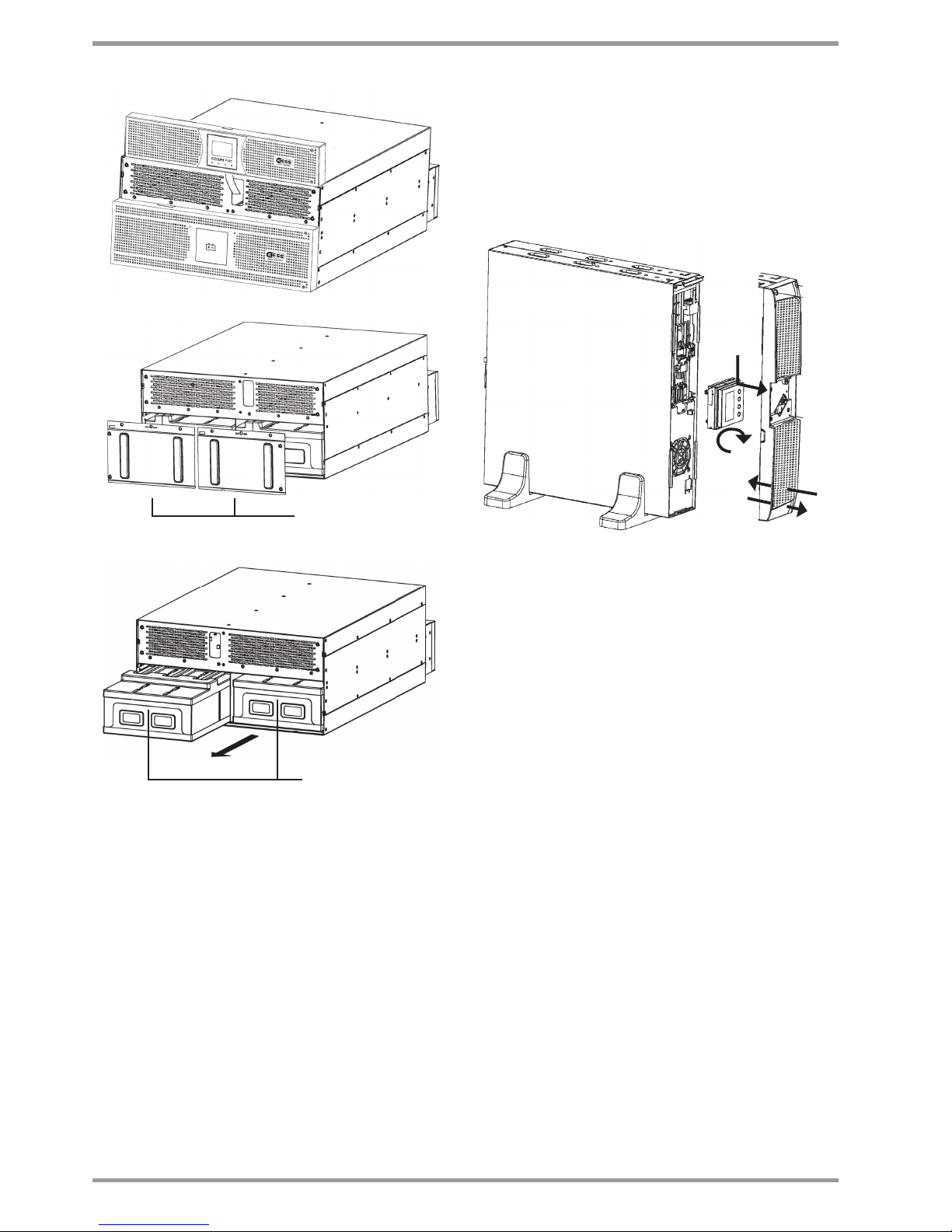
16
Power rate models from 8 to 10 KVA.
Blocking cover for battery
packs
Handle for battery pack
rack
Fig. 4. Battery pack/s removing.
4.2.5. Vertical -tower type- or rack models
• All the UPSs from KESSUPS 91RT series are designed to assemble
the equipment as tower format -vertical position of the equip-
ment- or rack -horizontal position- for its installation in 19" cabi-
nets.
Follow the instructions stated in the sections related to any of
both possibilities, attending the particular configuration of your
equipment.
• Figures from 5 to 10 show as an example an equipment up to 3
kVA. These illustrations are only for help and orientation in the
steps to follow and they are not particular for any model, because
in practice, the actions to make are the same for all models up to
6 kVA.
8 to 10 kVA models, the connection with battery modules for ex-
tended back up time, it is done through a connector located in
the rear side of the equipment (see figure 11).
• All the instructions relating to connections will detailed later on,
less those ones regarding the battery connection. Therefore, this
section will only describe the works linked with the assembling.
4.2.5.1. Rotation of control panel with LCD
Fig. 5. Rotation of control panel with LCD over the front cover.
• To make easier the message reading when the equipment is ver-
tically installed, it is advisable to rotate 90º clockwise the control
panel with LCD (see figure 5).
• Also, it is advised to rotate the control panel, if any tower type equip-
ment requires to be assembled as rack. Consider that the rotation of
the control panel will be counter clockwise.
• Proceed as follows:
Remove the front cover as it is stated in section 4.2.5.2
Slightly open the nails of the four trims that hold the control
panel with LCD to the front cover to free it and push inward
"A" to separate both parts.
Rotate it 90º on clockwise "B" and insert it again into the front
cover till click it "C". Check the correct closing of the fixing
nails.
Put the front cover back, in the reverse way as its removing
(see section 4.2.5.2).
90º
"A"
"B"
"C"

17
"A"
"C"
"B"
"D"
Fig. 6. Taking out the front cover.
4.2.5.2. Vertical -tower type-assembling
• Rotate the control panel according to section 4.2.5.1.
• In equipments up to 3 kVA, take the 4 plastic pieces "A" in angle
shape supplied with the equipment and joint them two by two
till obtain two supports or stabilizers "B".
• For equipments up to 3 kVA.
Put the UPS vertical between the two stabilizers supports "B"
(see figure 7).
For equipments of higher power.
Put the equipment vertical and fix the two metallic supports,
one at each side, by means of the supplied screws (models 4
to 6 KVA).
For equipment of 8 to 10 kVA, put the equipment vertical.
There are no supports or stabilizers.
"A"
"A"
"B"
Fig. 7. Vertical -tower type- assembling.
4.2.5.3. Vertical -tower type- assembling, with
extended back up time (battery module)
• The description of this section is based on an equipment with
only one battery module (see figure 8). For a higher quantity of
modules proceed to the connection among them.
• Rotate the control panel of the equipment according to section
4.2.5.1.
• In equipments up to 3 kVA, take the 4 plastic pieces "A" with angle
shape and supplied with the UPS and the two supplied with the
battery module "B", and joint them till obtain two supports or sta-
bilizers "C" to hold the equipment and battery module.
• For equipments up to 3 kVA.
Put the UPS and battery module on vertical position between
the stabilizers supports "C".
Fix the "D" metallic piece that joint UPS and battery module

18
by means of the supplied screws "E".
For equipments of higher power.
Put the equipment and battery module in vertical position
and together. Next fix the two metallic supports by means of
the supplied screws, one on the side of the equipment and
other one on the side of the battery module, in the UPS 4 to
6 kVA.
For equipment of 8 to 10 kVA, put the equipment vertical.
There are not supports or stabilizers.
Fix the joint metallic piece between the UPS and battery
module by means of the supplied screws.
"A"
"A" "B"
"C"
"F"
Fig. 8. Model in vertical -tower type- assembling with extended
back up time (battery module).
• Regarding the connections of the UPS with the battery module
in models up to 6 kVA, make the following steps, but reading sec-
tion 4.3.4 previously:
Connect the supplied earth joint cable "F", between the UPS
and battery module.
Remove the front cover of the equipment and battery
module, as it is described in section 4.2.5.2.
Take the extensible cable with connector "H" of the battery
module and connect it with the "G" connector of the equip-
ment.
To connect it with other battery modules, there is the "J" con-
nector. Take the extensible cable with "H" connector of the
beside battery module and connect it to the "J" connector of
"H"
"J"
"G"
"K"
"K"
"D"
"E"

19
the previous one. Repeat the same steps for a high quantity
of modules.
In the side of each front cover, there are the "K" trims as hole to
go the cables through it with the battery modules. Break the
needed trims to pass the connection bus.
Put the front cover back on the equipment and battery
module, as it is stated in section 4.2.5.2.
• For 8 and 10 kVA UPSs with the battery module, proceed as fol-
lows, but reading section 4.3.4 previously (see figure 11):
Connect the supplied earth joint cable , between the UPS
and battery module.
To connect the battery module with the equipment, there
is a connector on the rear side of both units. Insert the aerial
connector from battery module into the connector of the
equipment.
Battery module has base connector, foreseen to connect the
aerial connector from another module .
4.2.5.4. 19" rack cabinet mounting
• All models can be installed in a 19" rack cabinet, attending the
height of each model:
Models up to 3 kVA, 2 units height.
Models from 4 and 6 kVA,3 units height.
Models of 8 and 10 kVA, 5 units height.
"A"
"C"
"B"
Fig. 9. 19" rack cabinet assembling.
• To do it proceed as follows (see figure 9):
Fix both adaptor angles "A" of the equipment as rack, to its
side by means of the supplied screws.
Put a UPS in a rack cabinet, it is needed to have the side in-
ternal as support mode "C". In lack of them and under re-
quest, a rails can be supplied as a guide, to be installed by
the end user. Make the assembling at the required height,
assuring the correct torque of the fixing screws.
Face the equipment over the rails and enter it to the bottom.
Depending on the model of the equipment and as a result of
the weight, it is recommended to make the installation works
by two persons, and even more when they are done on the
top and bottom of the cabinet.
Fix the equipment to the frame of the cabinet by means of
the screws "B".
4.2.5.5. 19" rack cabinet assembling, with extended
back up time (battery module)
• This section describes a single equipment with only one battery
module (see figure 10). For higher quantity of modules repro-
duce the connection procedure among them.
• All models can be installed in a 19" rack cabinet, keeping in mind
the height of each model:
Models up to 3 kVA, height of 2 units.
Battery module for models up to 3 kVA, height of 2 units.
Models from 4 to 6 kVA, height of 3 units.
Models of 8 and 10 kVA, height of 5 units.
Battery module for models from 4 to 10 kVA, height of 3 units.
• To do this, proceed as follows:
Fix both adaptor angles "A" to the equipment and to the bat-
tery module as rack, on their side, by means of the supplied
screws.
Put a UPS in a rack cabinet, it is needed to have the side in-
ternal as support mode "C". In lack of them and under request,
a universal rails can be supplied as a guide, to be installed by
the end user. Make the assembling at the required height, as-
suring the correct torque of the fixing screws.
Face the equipment over the rails and enter it to the bottom.
Proceed in the same way for the battery module.
Depending on the weight of model of the equipment and
battery module, it is recommended to make the installation
works by two persons.
Fix the equipment to the frame of the cabinet by means of
the screws "B".
• Regarding the connections of the UPS with the battery module
in models up to 6 kVA, make the following steps, but reading sec-
tion 4.3.4 previously:
Connect the supplied earth joint cable "F", between the UPS
and battery module.
Remove the front cover of the equipment and battery
module, as it is described in section 4.2.5.2.
Take the extensible cable with connector "H" of the battery
module and connect it with the "G" connector of the equip-
ment.
To connect it with other battery modules, there is the "J" con-
nector. Take the extensible cable with "H" connector of the
beside battery module and connect it to the "J" connector of
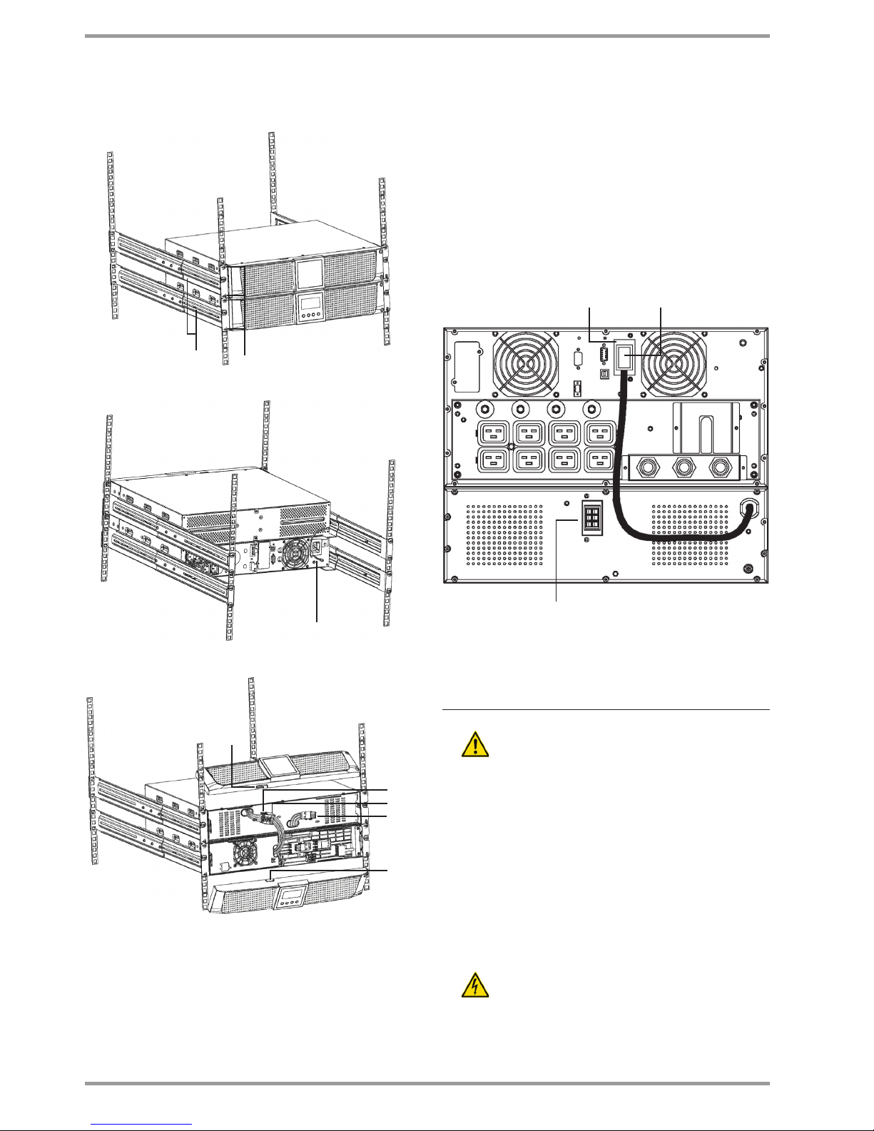
20
the previous one. Repeat the same steps for a high quantity
of modules.
"C" "B"
"F"
"G"
"J"
"K"
"K"
"H"
Fig. 10. 19" rack cabinet assembling, with extended back up
time (battery module).
In the side of each front cover, there are the "K" trims as hole to
go the cables through it with the battery modules. Break the
needed trims to pass the connection bus.
Put the front cover back of the equipment and battery
module, as it is stated in section 4.2.5.2.
• Regarding the connections of the UPS with the battery module
in models of 8 and 10 kVA, make the following steps, but reading
section 4.3.4 previously (see figure 11):
Connect the supplied earth joint cable, between the UPS and
battery module.
To connect the battery module with the equipment, there
is a connector on the rear side of both units. Insert the aerial
connector from battery module into the connector of the
equipment.
Battery module has base connector, foreseen to connect the
aerial connector from another module.
Base connector to connect it with
another battery module
Socket for battery
module
Wire of battery module
Fig. 11. Battery module connection for 8 and 10 kVA equipments.
4.3. Connection
• Cross cable section used in the power supply of the
equipment and loads to feed, will be sized according to
the nominal current stated in the nameplate sticked on the
equipment, by respecting the Low Voltage Electrotechnical Reg-
ulations or norms of the corresponding country.
• Installation will have the suitable input protections sized to the
current of the equipment and stated in the nameplate of the
equipment (optionally residual current devices and/or circuit
breaker with C characteristic or any other equivalent one).
Overload conditions are considered as a nonpermanent an ex-
ceptional operating mode, so these currents will not be kept in
mind when sizing the protections.
• Output protection will be done with a circuit breaker of C charac-
teristic or any other equivalent one.
• The equipments can be installed and used by personnel
with no specific training, just with only help of this
«Manual», less those ones with power blocks have to be installed
by qualified personnel.
This manual suits for next models
1
Table of contents
Other Kess UPS manuals


 Series user manual")


