3
Introduction
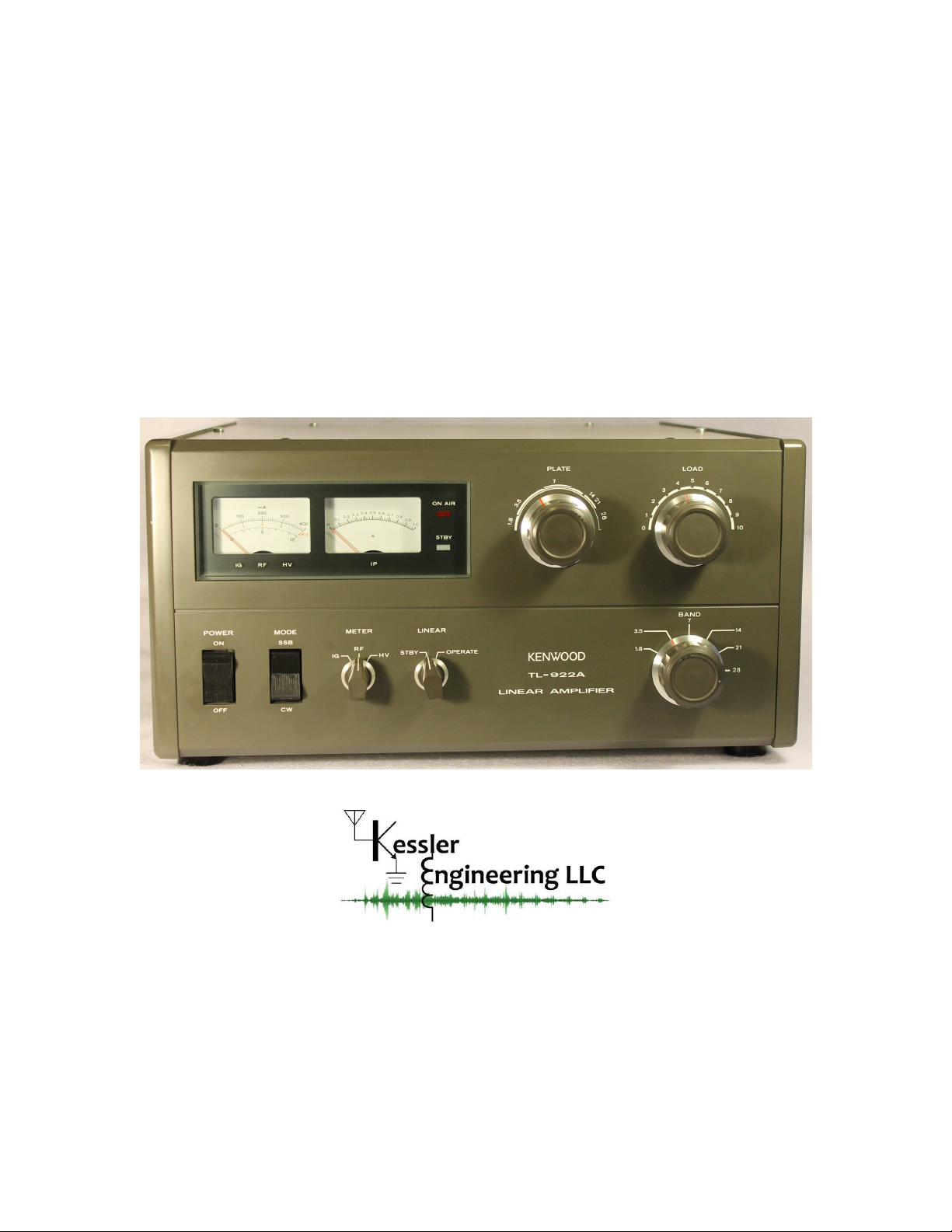
3.1 General Description and Purpose
The Kenwood TL-922/TL-922A is a relatively low-cost HF linear amplifier with outstanding
ergonomics. These amplifiers were constructed with high-quality components, in a form-
factor that is attractive, functional, and unobtrusive. Unfortunately that original design (now
30+ years old) included a number of design shortcomings, some of which were detrimental
to the amplifier’s operation and longevity.
Over the years, a number of excellent articles have been written, such as those published
by Richard Measures, AG6K, (SK) [3]-[7], that highlighted many of these problems and
provided very good solutions. By applying these solutions, the amplifier’s shortcomings may
be eliminated and its overall operation and longevity greatly enhanced. In short, a properly
modified TL-922 is a very reliable amplifier that will provide many years of flawless service.
A problem not always easily overcome by those seeking to perform these upgrades, is ex-
actly how and where to implement them as well as where to find appropriate sources of parts.
Another complication arises when one attempts to service a modified amplifier, particularly
if modified by someone else. Depending upon the modifier’s competency, willingness to doc-
ument, and overall “neatness”, troubleshooting such an amplifier can become a daunting
task. Kessler Engineering LLC has overcome these challenges for you by making the process
of upgrading the TL-922 amplifier much more practical, affordable, and serviceable.
Throughout this document, TL-922 will be used interchangeably to refer to both the
TL-922 and the TL-922A linear amplifiers. The TL-922 and TL-922A are (almost) identical
and these upgrades apply equally to both amplifiers. The TL-922 was sold throughout the
World as a 160m-10m linear amplifier. However, 10m operation was disabled at the factory in
order to permit importation into the United States, hence the TL-922 and TL-922A variants.
Although a stock TL-922A will not operate on 10m, all of the components necessary for 10m
operation were installed in the “A” variant and 10m operation may be enabled by removing
a mechanical stop on the bandswitch and minimal rewiring of the 10m tuned input network.
www.KesslerEngineeringLLC.com