Daily use
Daily use is very simple:
Use prox card and then enter the code.
Configure / Change User Codes
P [b or s] [yyy] [k] [z] [e] P or
b=programcode, s=systemcode 8 digits)
yyy = address
k = hold prox card in front of SA850 successful read is acknowledge with beeps)
z = user code def. in ‘Code length’)
e = max usage if none entered there are no limits)
Finishing:
P: Code is configured as an A-code Access but only if by-passed)
: Code is configured as an AB-code Access and By-pass)
If further codes must be configured the procedure can continue with yy.
If configuration is done terminate with P or
.
Delete user codes
P [b or s] [yyy] P
x = program code
yyy = address
P [b or s] P 12 0000 P
System– and program code are not affected. Only user code are deleted.
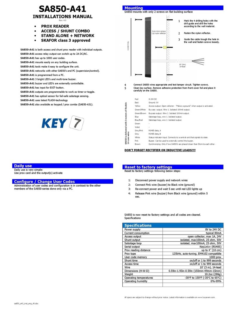
Mounting
mounts with only 2 screws on flat building surface
DON’T FO GET DIODE ON INDUCTIVE LOADS!!!!
eset to factory settings
Reset to factory settings following below step
SA850 is now reset to factory settings and all codes are cleared.
Specifications
Power supply 8V to 24V DC
Current consumption
typical 80mA
Access output
open collector, max 1A, 24V
Bell output
open collector, max 1A, 24V
open collector, max 1A, 24V
Sabotage loop
isolated, max100mA, 25 ohm, 50V
Prox type
125kHz, auto-tuning, EM4102 compatible
User code memory
1000 prox and/or 1000 key codes
By-pass time
on/off or 1 to 999 seconds
Access time
on/off or 1 to 999 seconds
Thread alarm time
3 seconds
Wire
10’ 3 m), 14-lead
Dimensions H-W-D)
0.59in-1.93in-0.59in 150mm-49mm-15mm)
Operating temperatures
-30°F to 150°F -35°C to 65°C)
All specs are subject to change without prior notice. Latest information is available on www.keyseven.com.
1
Mark the 4 drilling holes with the
drill guide and drill the holes
according to the wall material.
2
Fasten the nylon reflector.
3
Guide the cable trough the hole in
the wall and fasten screws loosely.
SA850 is delivered with 3 meters of flexible
14-core wire:
Red
8-24V DC
Access output. Open collector - "Makes a ground" when output is activated.
Green/White
By-pass output, wire 1. Isolated output.
pass output, wire 2. Isolated output.
Blue
Sabotage loop, wire 1. Isolated output.
Sabotage loop, wire 2. Isolated output.
Green
Bell output. Open collector - "Makes a ground" when output is activated.
Thread alarm output. Open collector
"Makes a ground" when output is activated.
Grey/Pink
RS485 data, A
Grey
RS485 data, B
White
Status indicator input. Connects to a central unit that signals its by-pass) state.
Buzzer. Can be used to externally control the buzzer.
Synchronizing. Only if two SA850’s are placed closer than 50cm to each other.
4
Connect SA850 wires appropriate and test tamper circuit with function 42
test)
. Tighten screws.
5
Clean key surface. Remove adhesive protection from front cover foil and place it
carefully on the SA850.
1:
Disconnect power supply and network wires
2:
Connect Pink wire buzzer) to Black wire ground)
3:
Re-connect power and wait 5 sec until red LED lights up
4:
Release Pink wire buzzer) from Black wire ground) within 5
sec.
SA850-A31
INSTALLATIONS MANUAL
Rev. 4.0
•P OX EADE + KBD
•ACCESS CONT OL
•BY-PASS
•STAND ALONE + NETWO K
•SKAFO cl. 3 approved
SA850-A31 is both access control and by-pass switch with individual outputs.
SA850-A31 isolated by-pass output and 1A open collector access output
SA850-A31 has up to 1000 user codes. SA850-A30 is for 100 users)
SA850-A31 mounts easily on any building surface.
SA850-A31 tools make it easy to configure the unit.
SA850-A31 networks with other SA850’s and PC supervision/control).
SA850-A31 can be programmed from the keypad or from a PC.
SA850-A31 ‘clickable’ keys, 3 bright LED’s and multi-tone buzzer.
SA850-A31 buzzer and LED’s are externally controllable.
SA850-A31 has a separate output for thread alarm secret code).
SA850-A31 has a bell button with dedicated output.
SA850-A31 has input for EXIT-button.
SA850-A31 outputs are programmable to work as timer or toggle.
SA850-A31 can be connected to PC or printer for log function.
SA850-A31 has optical sensor for sabotage sensing.
SA850-A31 also available without prox reader SA850-A20).
SA850-A31 also available without keypad SA850-A40).


