Keyscan NETCOM2 User manual

NETCOM2 - Rev. B Installation Guide
This guide outlines how to install and program the NETCOM2 Rev. B. The NETCOM2 Rev. B
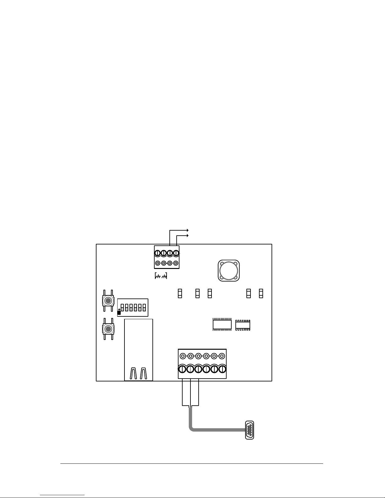
is a serial to Ethernet converter that utilizes an embedded TCP/IP device server and
requires an assigned static IP address as noted below under Before You Start. The
NETCOM2 Rev. B mounts inside the ACU/ECU enclosure. For mounting locations within the
ACU enclosure, refer to the 11 x 17 sheet that accompanied the control board or the
Technical Guide on the Keyscan Product Documentation Library CD.
New - Network Programming / Selectable DIP Switches
The NETCOM2 Rev. B is a redesigned version of the NETCOM2. You can now program the
NETCOM2 Rev. B using a local network connection from a server/laptop which has the
Keyscan NETCOM Utility installed.
In conjunction with its network programming capability, the NETCOM2 Rev. B has DIP
switches for setting one of the embedded programming IP addresses and selecting the bit
rate that matches the control boards on the communication loop. The DIP switches (S2)
are reviewed on page 5.
Before You Start
Verify that you have all the parts as outlined below
Obtain a static IP address, Subnet Mask, and, if applicable, a Gateway from the
network administrator for each NETCOM2 Rev. B. Space for recording addresses is
provided at the back
You may require the assistance of the network administrator for programming the
NETCOM2 Rev. B
Ensure that you install the latest Keyscan NETCOM Utility, which is on the enclosed
CD, on a server/laptop that has a local network connection to the NETCOM2 Rev. B
Contents
Pg
Programming Connection Methods
2
Section 1 –Install/Configure the NETCOM2 Rev. B
4
Switches S1, S2 & S3
5
Embedded Programming IP Address
5
Bit Rate Settings
6
Steps to Install and Configure the NETCOM2 Rev. B
6
Section 2 - Install the NETCOM Program Tool Utility and Program the NETCOM
9
Steps to Program the NETCOM2 Rev. B
10
Manually Configure a NETCOM Serially
13
Specifications
16
Address Settings
16
Parts
Qty
NETCOM2 Rev. B
1
Utilities and Drivers CD
1

Keyscan Inc. A Member of the Kaba Group
2
Programming Connection Methods
The NETCOM2 Rev. B can be programmed using one of the following connection methods:
Programmed using a local network connection via the RJ45 terminal
Programmed using a serial data cable (Keyscan part # 40-2322) via the TB2 terminal
block
Programmed using a network crossover cable via the RJ45 terminal
This document outlines the procedures for programming the NETCOM2 Rev. B using the
local network connection method which starts on page 4.
If you elect to use either the serial data cable or the network crossover programming
methods see the notes below.
Notes on Serial Data Cable Programming
The NETCOM2 Rev. B can be programmed with a serial data cable connected from the
server/laptop with the NETCOM Program Utility to the NETCOM2 Rev. B’s TB2 terminal
block as shown below. The NETCOM2 Rev. B requires a 12VDC power source. Ensure that
the DIP switch S2.1 is in the OFF position (Run mode). After establishing the connection,
open the NETCOM Program Utility, complete the necessary settings and program the
device. See Figure 3 or Figure 4 for permanent operating connections.
Figure 1 –Serial Data Cable Connection
RS-232 - 5 conductor
shielded 22 AWG cable
Black
Green
Red
to 12 VDC
power supply
to server/laptop
KI-00502E-10-14
12VDC
+-
RESET
GND TD RD DTRDCD I/O
EGND
RS-232TD RD POWER
LEDsLEDs
PRO GRAM
PRO GRAM
S1
S3
O
N
123456
NETCOM2 Rev. B
Red (+)
Black (-)
S2
RJ45

NETCOM2 Rev. B Installation Guide
3
Notes on Network Crossover Cable Programming
The NETCOM2 Rev. B can be programmed using a network cross over cable connected to
the NETCOM2 Rev. B’s RJ45 terminal. The NETCOM2 Rev. B requires a 12VDC power
source. Ensure that the DIP switch S2.1 is in the OFF position (Run mode). If you elect to
program it with the Network Connection via ARP Request, you require the NETCOM2 Rev.
B’s MAC address, which is printed on the RJ45 port. This method does not require setting
one of the NETCOM2 Rev. B’s embedded IP addresses. See Figure 3 or Figure 4 for
permanent operating connections.
Supplementary Documents
You may also require the following Keyscan documentation which can be located on the
Keyscan Products Documentation Library CD:
CIM Setup Guide
Keyscan Technical Guide
Prerequisites
NETCOM Program Utility version 6.0.16 or higher
Manually Configure the NETCOM2 Rev. B Serially
In the event that you program the NETCOM2 Rev. B using one of the three programming
connection methods previously reviewed and the device fails to communicate, refer to
manually configuring the device on page 13. You should only undertake these procedures if
you were unsuccessful programming the device with the NETCOM Program Tool Utility.

Keyscan Inc. A Member of the Kaba Group
4
Section 1 –Install/Configure the NETCOM2
Rev. B
This section outlines the procedures for installing and configuring the NETCOM2 Rev. B.
After completing the instructions in section 1, ensure you review and complete the
instructions in section 2.
Keyscan recommends that you review the document first, before beginning the installation.
Important
If you are installing more than one NETCOM2 Rev. B, do not apply power to more than one
NETCOM2 Rev. B at a time until each unit has been programmed with its assigned static IP
address. If you apply power to multiple NETCOM2 Rev. Bs while they are configured with
the same embedded programming IP address, you will create an address conflict on the
network. As a result, you will not be able to program the units.
Figure 2 - NETCOM2 Rev. B Circuit Board
12VDC
+-
RESET
GND TD RD DTRDCD I/O
Activity
LED
12VDC
from
DPS-15 LED Legend
- RS-232 indicates serial connection
- TD indicates PC polling ACU/ECU
- RD indicates ACU/ECU replying to
PC
- POWER indicates unit receiving
power
- PROGRAM indicates unit is
programming selected IP & bit rate
S1, S2, S3 Switches
- S1 –Reset
- S2.1 –Run/Program Mode*
- S2.2/3 –bits/second selection
- S2.4/5 –IP address selection
- S2.6 –Unassigned
- S3 –Starts program sequence
*Run mode for operating
*Program mode for on-board
programming firmware
Link
LED KI-00245E-08-13
EGND
RS-232TD RD POWER
LEDsLEDs
PROGRAM
PROGRAM
S1
S3
O
N123456S2

NETCOM2 Rev. B Installation Guide
5
Switches S1, S2 and S3
The NETCOM2 Rev. B’s switches S1, S2 and S3 are used to configure the device for the
functions outlined in Table 1.
The Steps to Install and Configure the NETCOM2 Rev. B will tell you which switches to set
and when to initiate setting the switches.
Table 1 –S1, S2 & S3 Switch Functions
Switch
Name
Setting
Function
S1
Reset
Press
momentarily
Resets the embedded device server
to prepare for programming
S2.1
Run/Program
Mode
Off = Run
On = Program
Sets the device for run mode
(operate) or enables S3 to initiate
program sequence (embedded
firmware)
S2.2 /
S2.3
Bit Rate
Selection
See Table 3
Configures the NETCOM2 Rev. B for
the specified bit rate/second
processing speed
S2.4 /
S2.5
Embedded
Programming IP
Address
Selection
See Table 2
Configures the NETCOM2 Rev. B
with an embedded programming IP
address for network connection to
program the device.
S2.6
Unassigned
N/A
S3
Program
Press
momentarily
S2.1 must be on. When pressed
initiates the program sequence for
the embedded firmware.
Embedded Programming IP Address
The NETCOM2 Rev. B has three (3) embedded programming addresses. You select one of
these addresses by setting the DIP switches S2.4 and S2.5 as outlined in Table 2. These
addresses act as a temporary IP to connect the NETCOM2 Rev. B with a server/laptop that
has the Keyscan NETCOM Utility. The NETCOM2 Rev. B and the server/laptop must be on a
local network for programming. The NETCOM2 Rev. B is not programmable via routers.
You must select an embedded programming IP address that matches the first three octets
used by your network. Octets are the series of numbers separated by a period (.).
Example of first three octets in an IP address - 192.168.100.
If you do not use matching octets you will not be able to communicate with the NETCOM2
Rev. B.
Table 2 –Embedded Programming IP Addresses/DIP Switch Settings
IP Address
S2.4
S2.5
Type
192.168.100.254
Off
Off
Static
10.0.100.254
Off
On
Static
169.254.100.254
On
Off
Static

Keyscan Inc. A Member of the Kaba Group
6
Using the Embedded IP Address as the Static IP Address
Although Keyscan does not recommend this, as an option the embedded programming IP
address may also be used as the static IP address. If you elect to do this you only need to
set the embedded IP address as outlined in the instructions below. The device does not
have to be programmed with the Keyscan NETCOM Program Utility. In the Client software,
the panels on the communication loop must have the embedded programming IP specified.
Using the embedded programming IP address restricts your communication with the panels
to a local network connection and you can only use a NETCOM2 Rev. B once per embedded
IP.
NETCOM2 Rev. B Bit Rate Setting
DIP switches S2.2 & S2.3 regulate the NETCOM2 Rev. B’s bit rate setting. The NETCOM2
Rev. B’s bit rate setting must match the bit rate setting of the control boards on the
communication loop. The bit rate on the control board is determined by J16 jumpers or S2
DIP switches. The bit rate is the number of bits processed per second at one of the speeds
listed in the table.
Table 3 –DIP Switch Bit Rate Settings
Bit Rate/Second
S2.2
S2.3
Notes
9,600
On
On
19,200
On
Off
57,600
Off
Off
Default
115,200
Off
On
Steps to Install and Configure the NETCOM2 Rev. B
Ensure that you know which embedded programming IP address to select based on the IP
addresses used on the network and you know the control board bit rate setting. Space is
provided at the back for recording the IP address, Subnet Mask, Gateway and MAC
address.
1. Mount and connect the NETCOM2 Rev. B as shown in either Figure 3 or Figure 4
within the ACU metal enclosure.
2. Ensure the S2.1 DIP switch is in the off position.
3. Connect the NETCOM2 Rev. B to the power. Observe that the POWER LED illuminates.
4. Set the S2.4 and S2.5 DIP switches to the correct embedded programming IP address
in accordance with the network. Refer to Table 2.
5. Set the S2.2 and S2.3 DIP switches to the same bit rate setting as the control boards.
Refer to Table 3. If connecting with DSC, match NETCOM to DSC bit rate setting.
6. Set the S2.1 DIP switch to the ON position.
7. Press and release the S3 PROGRAM button. Observe the PROGRAM LED illuminates –
solid –and the RD LED - flashes.
8. Press and release the S1 RESET button. Observe the following LED sequences:
After flashing for approximately 2 seconds the TD, RD and PROGRAM LEDs turn
off.
9. Change the S2.1 DIP switch to the off position.
Continued on the next page…

NETCOM2 Rev. B Installation Guide
7
10. The NETCOM2 Rev. B is configured and installed and ready for programming. Perform
any other necessary connections at the ACU.
11. Secure the ACU metal enclosure cover.
12. Proceed to Section 2 - Install the Keyscan NETCOM Utility and Program the NETCOM
on page 9.
Figure 3 - NETCOM2 Rev. B Connected to Control Board Communication Terminal
Server with Keyscan
Communication
Application/Service
- RS-232 DataCable
- Control Board
- Server/PC
- NETCOM2B
- 10/100 Base-TCable
10/100 Base-T
to
network
12 VDCto DPS15
to
network
RS-232
22 AWG shielded cable
Maximum - 100 ft (30 m)
GND
RS-232 (COM4)
Control Board
(PC 109x)
Green
Black
Connect shield to
enclosure ground lug at
one end of cable. Cut
shield off at other end and
ensure it is isolated.
TD
RD
DCD
DTR
CTS
Red
IOCB (COM1)
RX
TX
Parts List
KI-00163E-10-14
Control Board
S2 - DIP switches 7 & 8 = OFF (PC 1097 orlater)
or
J16 –pins F& G = OFF (PC 1094 & PC 1095)
12VDC
+-
RESET
GND TD RD DTRDCD I/O
EGND
RS-232TD RD POWER
LEDsLEDs
PRO GRAM
PRO GRAM
S1
S3
O
N
123456
Shield*
Brown & white not used. Tape
back separately.
to
ground lug
Green
Red
Black
LED Legend
- RS-232 indicates serial connection
- TD indicates PC polling ACU/ECU
- RD indicates ACU/ECU replying to
PC
- POWER indicates unit receiving
power
- PROGRAM indicates unit is
programming selectedIP & bit rate
S1, S2, S3 Switches
- S1 –Reset
- S2.1 –Run/Program Mode*
- S2.2/3 –bits/second selection
- S2.4/5 –IP address selection
- S2.6 –Unassigned
- S3 –Starts program sequence
* for on-board programming firmware
If using shielded Ethernet cable, connect
EGND terminal on NETCOM2B to
enclosure ground lug.
NETCOM2 Rev. B
*Insulate shield with PVC tubing such as
Alpha (p/n PVC10516 16 AWG) or
comparable insulator.
Red (+)
Black (-)
S2

Keyscan Inc. A Member of the Kaba Group
8
Figure 4 - NETCOM2 Rev. B Connected to CIM 0 Communication Terminal
Building to Building Communication
Where NETCOM2 Rev. Bs are used on a LAN/WAN integrating building-to-building
communication, a point-to-point private network is required.
CIM 0
Jumper ON J4
COMMON AUXINPUTS- E
17 18 19 20 21 22 23 24
IOCB (COM1)
RX
TX
CPB/CB COMMS
(COM4)
H2
COMMON AUXINPUTS- E
17 18 19 20 21 22 23 24
IOCB (COM1)
RX
TX
CPB/CB COMMS
(COM4)
TD1
RD1
TD2
RD2
GND
RTS
CTS
GND
RTS
CTS B3 B2 B1 B0 Diag
J2
RESET
-
CAN2
+
EGND
-
CAN1
+
GND
V +
(+12V)
SCKT1
PC106x
J1
J7
J8
J6
J5
CAN2
CAN1
1 2 1 2 1 2 1 2
Rx-COM COM
CAN CAN-Tx
J3J4 J9
J12
Power
Good
Fault
HDR1
J10J11
TD1
RD1
TD2
RD2
GND
RTS
CTS
GND
RTS
CTS B3 B2 B1 B0 Diag
J2
RESET
-
CAN2
+
EGND
-
CAN1
+
GND
V +
(+12V)
SCKT1
PC106x
J1
J7
J8
J6
J5
CAN2
CAN1
1 2 1 2 1 2 1 2
Rx-COM COM
CAN CAN-Tx
J3J4 J9
J12
Power
Good
Fault
HDR1
J10J11
Black
Green
Red CIM 0
CIM 1
CIM n
Slave
Global
Master
Termination Jumpers ON
J5 & J6 / J7 & J8
first & last CIM
Connect EGND
terminal on all
CIMs to ground
lugs in ACU
metal
enclosures.
Global Master
Jumper ON - J3
CAT 5
CAN Bus
Slave - Jumper OFF - J3
H2
H2
Shield*
to ACU
ground
lug
*Insulateshield with PVC tubing such as
Alpha (p/n PVC1051616 AWG) or
comparable insulator.
RS-232 - 5 conductor
shielded 22 AWG cable
CAT 5
CAN Bus
TerminationJumpers ON
J5 & J6 / J7 & J8
first & last CIM
Slave
H1
Slave - Jumper OFF - J3
H1
H1
White Orange
Orange
Blue
White Blue
Ground
White Orange
Orange
Blue
White Blue
Ground
White Orange
Orange
Blue
White Blue
Ground
KI-00469E-10-14
12 VDC to DPS15
- RS-232 Data Cable
- Control Board
- PC with network connection
- CIM
- NETCOM2B
- 10/100 Base-T Cable
- CAT 5 Cable –2 twisted pairs
Parts List
to network
10/100 Base-T cable
to network
Bit Rate / Jumper Settings (0 = OFF / 1 = ON)
Bit CIM Control Board
J9 J10 J11 J16 –1 2 6 S2 –2 3
9600 0 0 1 0 0 0 0 0
19200 0 1 0 0 1 0 1 0
57600 1 0 0 0 0 1 0 1
115200 1 0 1 0 1 1 1 1
Bit Rate / Distance
Bit CAN Bus RS-232
9600 3280' (999.7 m) 49.2' (14.9 m)
19200 3280' (999.7 m) 49.2' (14.9 m)
57600 984' (299.9 m) 26.2' (7.9 m)
115200 262' (80 m) 9.84' (3 m)
Note
CIM 0 / NETCOM6B does not support a
reverse network connection. CIM 0 requires
a NETCOM6P for reverse network.
Server with Keyscan
Communication Application/
Service
12VDC
+-
RESET
GND TD RD DTRDCD I/O
EGND
RS-232TD RD POWER
LEDsLEDs
PRO GRAM
PRO GRAM
S1 S2
O
N123456
Black
Green
Red
Red (+)
Black (-)
Connect shield to enclosure
ground lug at one end of RS-232
cable. Cut shield off at other end
and ensure it is islolated.
If using shielded Ethernet
cable, connect EGND
terminal on NETCOM2B/6B
to enclosure ground lug.
S3 NETCOM2
Rev. B

NETCOM2 Rev. B Installation Guide
9
Section 2 - Install the Keyscan NETCOM Utility
and Program the NETCOM
Each NETCOM2 Rev. B that you have installed must be programmed with the Keyscan
NETCOM Program Utility which is on the enclosed Utilities and Drivers CD. To install the
Keyscan NETCOM Program Utility, load the CD into the CD-ROM or DVD drive. The utility is
set on auto-start. Follow the on-screen prompts.
NETCOM2 Rev. B requires Keyscan NETCOM Utility version 6.0.16 or higher
The server/laptop IP address must have the same first three octets as the embedded
programming IP address set on the NETCOM2 Rev. B from section 1.
If your server IPs do not match the first three octets as the embedded programming
IP address on the NETCOM2 Rev. B, see IP Address Examples below and steps to set
a static IP address for the server/laptop
If your server IPs match the first three octets as the embedded programming IP
address on the NETCOM2 Rev. B, go to Steps to Program the NETCOM2 Rev. B
IP Address Examples
The following three examples show the embedded programming IP address and valid
corresponding IP addresses for the server/laptop.
Table 4 –Valid Subnet Server Examples
NETCOM2 Rev. B –IP Address
Valid Server IP Address
192.168.100.254
192.168.100.20
10.0.100.254
10.0.100.33
169.254.100.254
169.254.100.100
Steps to Set a Static IP Address for the Server/Laptop
These steps apply to most Windows operating systems. You must have installed the
NETCOM Program Tool Utility to perform the procedures below.
1. Select Start > All Programs > Keyscan NETCOM Program Tool > Keyscan NETCOM
Program Tool.
2. From the Keyscan NETCOM Utility screen, click on the Network Connections button.
3. Right click on Local Area Connection > Properties.
4. Select Internet Protocol Version 4 (TCP/IPv4). Select the Properties button.
5. Click in the radio button opposite Use the following IP address:
6. Enter the correct IP address and subnet mask.
7. Click on OK.
8. Click on OK.
9. Click on the X in the upper right of the Local Area Connection screen to exit.
10. Complete the Steps to Program the NETCOM2 Rev. B.

Keyscan Inc. A Member of the Kaba Group
10
Steps to Program the NETCOM2 Rev. B
These instructions assume you have completed section 1 and the Keyscan NETCOM Utility
is installed on a server/laptop connected on a local network with the NETCOM2 Rev. B. If
you are continuing from Steps to Set a Static IP Address for the Server/Laptop go to step
2.
1. Select start > All Programs > Keyscan NETCOM Program Tool > Keyscan NETCOM
Program Tool.
2. From the Keyscan NETCOM Utility screen, click Program NETCOM Device.
3. From the Select NETCOM Device Type, click on the NETCOM2 Family of Boards.
4. From the Program NETCOM2B, NETCOM2 & NETCOM2P screen, enter the assigned IP
address. This is not to be confused with the embedded programming IP address.
5. Enter the Subnet Mask by selecting an address from the drop down list.
6. For a gateway, optional, enter the number in the Default Gateway text box.

NETCOM2 Rev. B Installation Guide
11
Depending on the network configuration, the Subnet Mask and Gateway settings
are in relation to network communication between the NETCOM2 Rev. B and the
server with the Keyscan communication application or service.
7. From Program via IP Address or Serial Port, select the embedded programming IP
address that the NETCOM2B’s S2.4 & S2.5 DIP switches were set on.
If Network Connection via ARP Request is selected, enter the NETCOM2 Rev. B’s
MAC address printed on the RJ45 terminal in the MAC Address boxes.
8. Click on the down arrow below and to the right of Communication Baud Rate and
select the bit rate that corresponds to the NETCOM2 Rev. Bs S2.2 & S2.3 DIP
switches.
9. Leave Ethernet Connection Type on Automatic Negotiation unless given a specific
setting by the IT administrator.
If the NETCOM device experiences network communication difficulties, you may
have to alter the Ethernet Connection Type from automatic negotiation. (The
Ethernet Connection Type is the network speed & duplex setting). Set the
NETCOM so it matches the network equipment setting. If the network equipment
was on an automatic setting, then reconfigure both the network equipment,
which may include routers or switches, and the NETCOM to a matching fixed
speed and duplex setting. As an example, NETCOM = 100 Mbit/Half Duplex –
Network equipment = 100Mbit/Half Duplex.
10. The Discovery Port 77FE setting is disabled by default. Keyscan recommends that you
leave it on the default setting. This function is principally for troubleshooting
communication difficulties.
If you de-select the Disable Discovery Port 77FE function (the box does not have
a check mark) the Discover NETCOM Devices function will list the device by its
MAC address and IP address if it is located on the network.
11. Click on the Program NETCOM button. Wait while the utility programs the device.
12. From the Program Device via Network Connection prompt –Your NETCOM2 device
has been configured, click on the OK button.
13. Click on the Exit button of the Program NETCOM2B, NETCOM2 & NETCOM2P Boards
screen.
14. From the Keyscan NETCOM Utility screen, verify network communication with the
NETCOM2 Rev. B by selecting the Start Ping button.
Continued on the next page…

Keyscan Inc. A Member of the Kaba Group
12
15. Wait for the PING Status result message:
IP Success indicates the NETCOM2 Rev. B has network communication
IP Timed Out indicates the NETCOM2 Rev. B does not have network
communication—verify settings and connections*
16. Click on the x in the upper right corner of the Keyscan NETCOM Utility screen to close
the application.
17. If the installation of the NETCOM2 Rev. B has altered panel communication, open a
Keyscan Client software module, log on, make the necessary panel setting changes,
and perform an upload.
If this is a new installation, refer to the Keyscan Software Installation Guide on
how to install the Keyscan software, configure system communication and set up
a site.
* If the IP address was not accepted by the NETCOM2 Rev. B on the 1st attempt, return to
the Program NETCOM2B, NETCOM2 & NETCOM2P Boards screen and press the F4 key on
the keyboard. Click inside the box to the left of Program Server Address Settings Only so it
has a check mark. Re-enter the settings, including the IP Address. Click on the Program
NETCOM button. If successful, program the NETCOM one more time. For additional
programming tips, press the F1 key with the Keyscan NETCOM Program Settings screen
open.
Important
If you experience communication difficulties, you may have to program the NETCOM2 Rev.
B following the procedures outlined in Manually Configure the NETCOM2 Serially on page
13.

NETCOM2 Rev. B Installation Guide
13
Manually Configure the NETCOM2 Rev. B Serially
These procedures should only be performed in the event that the Keyscan NETCOM Utility
was used to program the NETCOM2 Rev. B in section 2 and the device is still failing to
communicate. These procedures are intended for advanced computer users only. You
require a data serial cable (Keyscan part # 40 –2322).
Important
Keyscan recommends that you review the setup procedures before performing them so you
are familiar with the steps, some of which are intricate and require quick dexterity.
1. With the serial data cable establish a connection to the server/laptop that has the
NETCOM Program Tool utility.
2. Open the NETCOM Program Tool utility and select the Keyscan Hyper Terminal Button.
3. Set the Comm Port Number if you are connected via a serial port other than
communication port #1.
4. Leave the baud rate set on 9600. Click on the Open Port button.
5. To enter Setup Mode, reset the NETCOM2, either by pushing the reset button or
cycling the unit’s power (power off and back on).
6. Within 1 second of the NETCOM2 reset, enter 3 lowercase x characters—xxx.
Tip—The easiest way to enter Setup Mode is to hold down the x key at the
keyboard terminal while resetting the unit.
7. When the Setup Mode window opens, press the Enter key within 5 seconds to enter
setup mode.
RS-232 - 5 conductor
shielded 22 AWG cable
Black
Green
Red
to 12 VDC
power supply
to server/laptop
KI-00502E-10-14
12VDC
+-
RESET
GND TD RD DTRDCD I/O
EGND
RS-232TD RD POWER
LEDsLEDs
PRO GRAM
PRO GRAM
S1
S3
O
N
123456
NETCOM2 Rev. B
Red (+)
Black (-)
S2
RJ45

Keyscan Inc. A Member of the Kaba Group
14
8. Once you reach the Change Setup: prompt, Press 0 for Server setup parameters and
enter the following values for 0 Server (Keyscan values)
0 Server (User Defined Values)
IP Address: Enter the User Static IP Address, and press the Enter key.
Set Gateway IP Addr: Press the Y key for yes or the N key for no.
If Y was selected in the previous step, then enter the Gateway IP address, and
press the Enter key.
Netmask: Specify the Netmask by entering its list number (the number on the
left opposite the Netmask) and press the Enter key.
3= 255.255.255.248
4= 255.255.255.240
5=255.255.255.224
6= 255.255.255.192
7= 255.255.255.128
8= 255.255.255.0 (Default)
9= 255.255.254.0
10 = 255.255.252.0
11 = 255.255.248.0
12 = 255.255.240.0
13 = 255.255.224.0
14 = 255.255.192.0
15 = 255.255.128.0
16 = 255.255.0.0
17 = 255.254.0.0
18 = 255.252.0.0
19 = 255.248.0.0
20 = 255.240.0.0
21 = 255.224.0.0
22 = 255.192.0.0
23 = 255.128.0.0
24 = 255.0.0.0
Set DNS Server IP addr: Press the N key for no.
Change telnet config password: Press the N key for no.
9. After completing the Server parameters, press 1 for Channel 1 setup parameters and
enter the following Keyscan values. Press the Enter key after each entry.
1 Channel 1 (Keyscan Values)
Baudrate = 9600 (Must match ACU settings)
I/F Mode =4C
Flow = 00
Port No. =3001
ConnectMode =C0
Send ‘+++’ in Modem Mode =N
Show IP addr after ‘RING’ = N
Remote IP Address = 000.000.000.000
Remote Port = 0
DisConnMode =00
FlushMode =80
Pack Cntrl =01

NETCOM2 Rev. B Installation Guide
15
DisConnTime =15:00
SendChar 1 =00
SendChar 2 =00
10. After completing the Channel 1 parameters, Press 9 to save the configuration and
restart the NETCOM2 unit.
Note
To exit without saving any changes, press 8.

Keyscan Inc. A Member of the Kaba Group
16
Specifications
Input Power Requirements
12VDC, 270mA. Powered by DPS15
Maximum Cable Lengths
ACU/ECU to NETCOM2 Rev. B—22 AWG 5 conductor shielded - max 100 feet /30 m
CIM to NETCOM2 Rev. B—22 AWG 5 conductor shielded - max 49.2 ft/14.9 m @ 9600 bps
Network Communication
Existing LAN or WAN (TCP/IP protocol—port 3001)
Agency Approvals—Ethernet Socket
Complies with Class B limits of EN 55022: 1998 Direct & Indirect ESD.
Complies with EN55024:1998
Dimensions
3.031” x 3.896” (77 mm x 99 mm)
Environmental
Suitable for industrial and commercial applications.
Operating temperatures: 50C to 700C (410F to 1580F)
RJ45 Ethernet (Xport) LED States
The RJ45 Ethernet terminal has two bi-colour LEDs:
Link LED (left side)
Activity LED (right side)
Amber –flashing
10 Mbps
Amber –flashing
Half-duplex
Green –flashing
100 Mbps
Green –flashing
Full-duplex
Address Settings
*IP Address:
*Subnet Mask:
Gateway:
**Ethernet Connection
Type:
MAC Address
* Required fields for device configuration with software
** If other than Automatic Negotiation
Keyscan Inc.
901 Burns St., E. Whitby, Ontario, Canada L1N 0E6
1.888.539.7226 (toll free Canada/USA)
905.430.7226 (elsewhere)
www.keyscan.ca
Technical Support
Hours –9:00 A.M. to 6:30 P.M. Eastern Time
NETCOM2 Rev. B Installation Guide (PC109x –07.15)
Table of contents
Popular Media Converter manuals by other brands

MDS Power
MDS Power VTCi320 Installation and operation manual

LINK-MI
LINK-MI LM-DA03 user manual

Littfinski Daten Technik
Littfinski Daten Technik S-DEC-4-MM-B Assembly instruction

Rose electronics
Rose electronics CNV-UHD-HD/SC Installation and operation manual

Honeywell
Honeywell NX series user manual

VigilLink
VigilLink VLSP-18CTH14 user manual