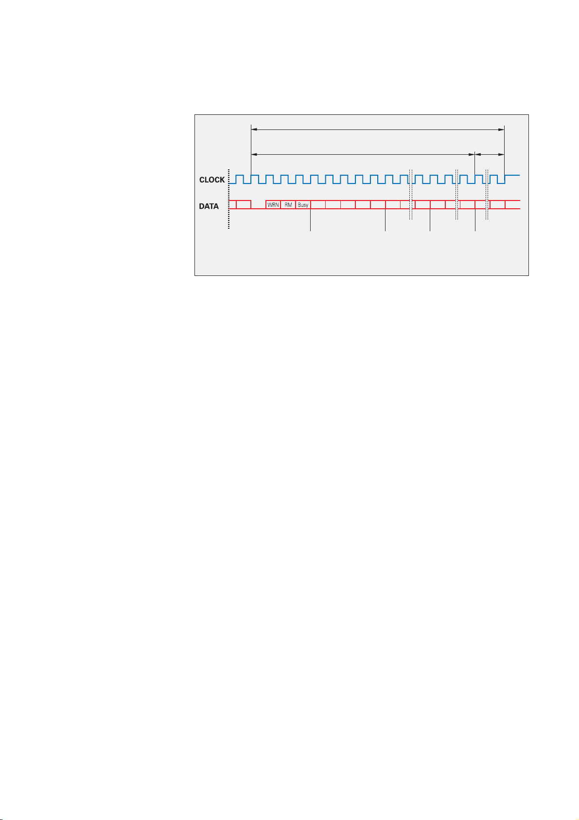
manuals.online logo
Brands
  1. Home
  2. •
  3. Brands
  4. •
  5. HEIDENHAIN
  6. •
  7. Media Converter
  8. •
  9. HEIDENHAIN EnDat 2.2 Manual

HEIDENHAIN EnDat 2.2 Manual

Other manuals for EnDat 2.2

1

Other HEIDENHAIN Media Converter manuals

HEIDENHAIN LC 2 1 Series User manual

HEIDENHAIN

HEIDENHAIN LC 2 1 Series User manual

HEIDENHAIN EIB 741 User manual

HEIDENHAIN

HEIDENHAIN EIB 741 User manual

HEIDENHAIN ECN 125 User manual

HEIDENHAIN

HEIDENHAIN ECN 125 User manual

HEIDENHAIN MSL 41 User manual

HEIDENHAIN

HEIDENHAIN MSL 41 User manual

HEIDENHAIN LIP 481R User manual

HEIDENHAIN

HEIDENHAIN LIP 481R User manual

HEIDENHAIN ERP 880 User manual

HEIDENHAIN

HEIDENHAIN ERP 880 User manual

HEIDENHAIN LIDA 573 User manual

HEIDENHAIN

HEIDENHAIN LIDA 573 User manual

HEIDENHAIN LIF 171R User manual

HEIDENHAIN

HEIDENHAIN LIF 171R User manual

HEIDENHAIN ECN 1113 User manual

HEIDENHAIN

HEIDENHAIN ECN 1113 User manual

HEIDENHAIN TTR ERM 2200 C User manual

HEIDENHAIN

HEIDENHAIN TTR ERM 2200 C User manual

HEIDENHAIN ECN 1313 EnDat01 User manual

HEIDENHAIN

HEIDENHAIN ECN 1313 EnDat01 User manual

HEIDENHAIN LIP 581R User manual

HEIDENHAIN

HEIDENHAIN LIP 581R User manual

HEIDENHAIN LIP 481 V User manual

HEIDENHAIN

HEIDENHAIN LIP 481 V User manual

HEIDENHAIN ECN 1325 EnDat22 User manual

HEIDENHAIN

HEIDENHAIN ECN 1325 EnDat22 User manual

HEIDENHAIN AK ERP 10 Series User manual

HEIDENHAIN

HEIDENHAIN AK ERP 10 Series User manual

HEIDENHAIN LIF 481R User manual

HEIDENHAIN

HEIDENHAIN LIF 481R User manual

HEIDENHAIN KCI 1319 User manual

HEIDENHAIN

HEIDENHAIN KCI 1319 User manual

HEIDENHAIN LC 2 1 Series User manual

HEIDENHAIN

HEIDENHAIN LC 2 1 Series User manual

HEIDENHAIN LIDA 407 User manual

HEIDENHAIN

HEIDENHAIN LIDA 407 User manual

HEIDENHAIN ECN 1324 S User manual

HEIDENHAIN

HEIDENHAIN ECN 1324 S User manual

HEIDENHAIN LS 6 8 C Series User manual

HEIDENHAIN

HEIDENHAIN LS 6 8 C Series User manual

HEIDENHAIN ECI 119 EnDat01 User manual

HEIDENHAIN

HEIDENHAIN ECI 119 EnDat01 User manual

HEIDENHAIN LIC 3107 User manual

HEIDENHAIN

HEIDENHAIN LIC 3107 User manual

HEIDENHAIN LIP 401R User manual

HEIDENHAIN

HEIDENHAIN LIP 401R User manual

Popular Media Converter manuals by other brands

SoundTraxx Blunami BLU-2200 user guide

SoundTraxx

SoundTraxx Blunami BLU-2200 user guide

SPROLINK VA1 user manual

SPROLINK

SPROLINK VA1 user manual

Acclaim Lighting DDC-1-AC user guide

Acclaim Lighting

Acclaim Lighting DDC-1-AC user guide

Nikon AF-S TC-20E III user manual

Nikon

Nikon AF-S TC-20E III user manual

Axis AXIS Q7406 user manual

Axis

Axis AXIS Q7406 user manual

Omega TAC80B-J instruction sheet

Omega

Omega TAC80B-J instruction sheet

Zoom Thunderbolt TAC-2R Operation manual

Zoom

Zoom Thunderbolt TAC-2R Operation manual

OST iConverter 10/100M quick start guide

OST

OST iConverter 10/100M quick start guide

Vertiv Netsure user manual

Vertiv

Vertiv Netsure user manual

birddog MINI user guide

birddog

birddog MINI user guide

Roland GI-10 owner's manual

Roland

Roland GI-10 owner's manual

Wallenstein WX310 Operator's manual

Wallenstein

Wallenstein WX310 Operator's manual

Pace MSS 200-1 Service manual

Pace

Pace MSS 200-1 Service manual

Solar Converters EQ 12/24-50 manual

Solar Converters

Solar Converters EQ 12/24-50 manual

CYP EL-7400V Operation manual

CYP

CYP EL-7400V Operation manual

TIE MIDI 1i1o user manual

TIE

TIE MIDI 1i1o user manual

DCS Vivaldi Upsampler user manual

DCS

DCS Vivaldi Upsampler user manual

Westermo MCW-211 SERIES user guide

Westermo

Westermo MCW-211 SERIES user guide

manuals.online logo
manuals.online logoBrands
  • About & Mission
  • Contact us
  • Privacy Policy
  • Terms and Conditions

Copyright 2025 Manuals.Online. All Rights Reserved.

Digital drive systems and feedback loops with position encoders for measured value acquisition require fast data transfer with high
transmission reliability from the encoders. Further data, such as drive-specific parameters, compensation tables, etc. must also be
made available. For high system reliability, the encoders must be integrated in routines for error detection and have diagnostic
capabilities.
The EnDat interface from HEIDENHAIN is a digital, bidirectional interface for encoders. It is capable both of transmitting position values
from incremental and absolute encoders as well as transmitting or updating information stored in the encoder, or saving new information.
Thanks to the serial transmission method, only four signal lines are required. The data are transmitted in synchronism with the clock
signal from the subsequent electronics.The type of transmission (position values, parameters, diagnostics, etc.) is selected through
mode commands that the subsequent electronics send to the encoder.The EnDat 2.2 interface, a purely serial interface, is also suited for
safety-related applications.
Technical Information
EnDat 2.2 – Bidirectional Interface for Position Encoders
Power supply
CLOCK 16 MHz
DATA Position values, parameters, datum shifts,
electronic ID label, diagnostics, warning, etc.
2
The EnDat interface provides everything
needed to reduce system cost—per axis
up to 50%—and at the same time improve
the technical standard.The most significant
benefits are:
Cost optimization
A single interface for all absolute and• incremental encoders
Simple subsequent electronics with• EnDat receiver chip and standard
components
Simpler, more economical power supply,• since remote sensing is not required
Simple connection technology: Standard• connecting elements (M12 – 8-pin),
single shielded standard cable and low
wiring costs
Small motor or system dimensions• through compact connecting elements
No expensive additional sensory analysis• and wiring: EnDat 2.2 transmits
additional data (limit switch/temperature/
acceleration)
Faster configuration during installation:• Datum shifting through offsetting by a
value in the encoder
Improved quality
Higher system accuracy through specific• optimization in the encoder
High contour accuracy, particularly for• CNC machine tools: position value
formation in the encoder permits shorter
sampling intervals without influencing
the computing time of the CNC
Higher availability
Automatic configuration of the system• axis: all necessary information can be
saved in the encoder (electronic ID label).
High system reliability through purely• digital data transmission
Diagnostics through monitoring• messages and warnings that can be
evaluated in the subsequent electronics
High transmission reliability through• cyclic redundancy checking
Safety system
EnDat 2.2 was conceived for safety-• related machine designs
Two independent position values for• error detection
Two independent error messages• Checksums and acknowledgments• Forced dynamic sampling of error• messages and CIRCLE formation by
subsequent electronics
Support for state-of-the-art machine
designs
Suitable for direct drive technology• thanks to high resolution, short cycle
times and commutation information
Cyclic sampling every 25 µs with full• “read and write” mode
Position values available in the• subsequent electronics after only approx.
10 µs
Miniature connecting
element, M12, 8-pin
Simple connection technology,
8-wire cable, single shielding
Integrated interpolation and position value
formation, temperature measurement
Connecting element,
e.g. M12, D-sub
Power supply without remote
sensing
(UP= 3.6 to 5.25 V or
3.6 to 14 V)
Simple subsequent electronics with
EnDat 2.2 receiver chip and standard
components (“EnDat Master”)
* For parallel power supply lines
Benefits of the EnDat Interface
For further information on implementing
EnDat or additional documents, see
www.EnDat.de
3
The extended EnDat interface version 2.2
is compatible in its communication,
command set and time conditions with
the previous version 2.1, but also offers
significant advantages. It makes it possible,
for example, to transfer what is termed
“additional data” with the position value
without sending a separate request for it.
The interface protocol was expanded and
the time conditions were optimized as
follows:
Increased clock frequency (CLOCK)• (16 MHz)
Optimized calculating time (position• value acquisition within 5 µs)
Minimized dead time (recovery time)• (1.25 to 3.75 µs)
Expanded power supply range (U• P= 3.6
to 5.25 V or 3.6 to 14 V at encoder)
EnDat 2.2 command set (includes EnDat 2.1 command set)
•Position values for incremental and absolute encoders
•Additional data on the position value
’Diagnostics, test values
’Absolute position values after reference run of incremental encoders
’Parameter upload/download
’Commutation
’Acceleration
’Limit position signal
’Position value 2 for safety-related applications or incremental encoders
EnDat 2.1 command set
•Absolute position values
•Send and receive parameters
•Reset
•Test command
•Test values
The EnDat interface transmits position
values or additional physical quantities in an
unambiguous time sequence and serves to
read out from and write to the encoder’s
internal memory.
1. Position values can be transmitted with
or without additional data. The additional
data types are selectable via the
Memory Range Select (MRS) code.
Other functions such as parameter
reading and writing can also be called
after the memory area has been
selected. Through simultaneous
transmission with the position value,
additional data can also be requested of
axes in the feedback loop, and functions
executed with them.
2. Parameter reading and writing is
possible both as a separate function and
in connection with the position value.
Parameters can be read or written after
the memory area is selected.
3. Reset functions serve to reset the
encoder in case of malfunction. Reset is
possible instead of or during position
value transmission.
4. Test commands and values are used
for forced dynamic sampling in safety-
related controls.The significance of the
error message is inverted in order to
monitor its generation.
Compatibility of EnDat 2.2 > 2.1
Description of Function
S
CRC
F1 DD
DD
CRC CRC CRC CRC
2T 2T
0
S
CRC
00111
000111
F1 D
t
D
DDD
CRC CRC CRC CRC
4
A clock pulse (CLOCK) is transmitted by
the subsequent electronics to synchronize
data transmission. When not transmitting,
the clock signal is on high level.
Clock frequency and cable length
Without propagation-delay compensation,
the clock frequency is variable between
100 kHz and 2 MHz, depending on the
cable length. Because large cable lengths
and high clock frequencies increase the
signal run time to the point that they can
disturb the unambiguous assignment of
data, the delay can be measured in a test
run and then compensated. With this
propagation-delay compensation in the
subsequent electronics, clock frequencies
up to 16 MHz at cable lengths up to a
maximum of 100 m (fC† 8 MHz) are
possible.The maximum clock frequency is
mainly determined by the cables and
connecting elements used.To ensure
proper function at clock frequencies above
2 MHz, use only original HEIDENHAIN
cables.
The permissible clock frequencies shown
in the diagrams apply for a clock on-off
ratio of 1:1. This means that the HIGH and
LOW levels of the clock are equally long.
For other on-off ratios, the theoretical clock
frequency is calculated as FCL =
Determining the propagation time
After every change in the transmission line
hardware, the propagation time must be
ascertained—preferably automatically after
every power interruption.
The subsequent electronics transmit the
mode command Encoder transmit position
values without additional data to the
encoder. After the encoder has switched to
transmission, i.e. after in total 10 clock
periods, a counter in the subsequent
electronics starts with every rising edge.
The subsequent electronics measure the
Clock frequency
Clock frequency [kHz]
Cable length [m]
Without delay compensation
With delay compensation
Clock on-off ratio
Clock
propagation time as the difference
between the last rising clock pulse edge
and the edge of the start bit. The process
should be repeated at least three times in
order to rule out any disturbances during
the calculation of the propagation time and
to test the value for consistency.The signal
propagation time is measured at a reduced
clock frequency (100 kHz to 200 kHz). To
attain sufficient accuracy, however, the
value must be sampled at an internal
frequency that is at least eight times higher
than the clock frequency to be used later
for data transmission.
1
2tmin
Clock pulse
transmitted to
the encoder
Clock pulse at
encoder
Data at
encoder
Start counter
Data at subs.
electronics
Mode
Mode command
Clock frequency 100 kHz to 200 kHz
S= start, F1 = error, D= data
DataTransfer
5
Transmitted data are identified as either
position values, position values with
additional data, or parameters. The type of
information to be transmitted is selected
by mode commands. Mode commands
define the content of the transmitted
information. Every mode command
consists of three bits.To ensure reliable
transmission, every bit is transmitted
redundantly (inverted or double). If the
encoder detects an incorrect mode
transmission, it transmits an error
message.The EnDat 2.2 interface can also
transfer parameter values in the additional
data together with the position value.This
makes the current position values
constantly available for the control loop,
even during a parameter request.
Mode bit
No. Mode command M2 M1 M0 (M2) (M1) (M0)
1 Encoder send position values
EnDat 2.1 command set
EnDat 2.2 command set
000111
2 Selection of memory area 0 0 1 1 1 0
3 Encoder receive parameter 0 1 1 1 0 0
4 Encoder send parameter 1 0 0 0 1 1
5 Encoder receive reset1) 101010
6 Encoder send test values 0 1 0 1 0 1
7 Encoder receive test command 1 1 0 0 0 1
8 Encoder send position value with additional
data 111000
9 Encoder send position value and receive
selection of memory area 2) 001001
10 Encoder send position value and receive
parameter2) 011011
11 Encoder send position value and send
parameter2) 100100
12 Encoder send position value and receive
error reset2) 101101
13 Encoder send position value and receive
test command2) 110110
14 Encoder receive communication command3) 010010
1) Same reaction as from switching the power supply off and on
2) Selected additional data is also transmitted
3) Reserved for encoders that do not support the safety system
The time absolute linear encoders need for
calculating the position values tcalf
sometimes differs depending on whether
EnDat-2.1 or EnDat-2.2 mode commands
are transmitted (see catalog: Linear
Encoders for Numerically Controlled
MachineTools – Specifications). If the
incremental signals are evaluated for axis
control, then the EnDat 2.1 mode
commands should be used. Only in this
manner can an active error message be
transmitted synchronously with the
currently requested position value.
EnDat 2.1 mode commands should
not be used for purely serial position-value
transfer for axis control.
Selecting theTransmissionType
6
For every data transfer one data packet is
transmitted in synchronism with the clock
signal.The transmission cycle begins with
the first falling clock edge.The measured
values are saved and the position value is
calculated.
After two clock pulses (2T), the subsequent
electronics transmit the mode command
Encoder transmit position value (with/
without additional data).
After successful calculation of the absolute
position value (tcalf—see table), the start
bit begins the data transmission from the
encoder to the subsequent electronics.
The subsequent error bits, error 1 and
error 2 (only with EnDat 2.2 commands),
are group signals for all monitored functions
and serve for failure monitoring. They are
generated separately from each other and
indicate when a malfunction of the encoder
can result in incorrect position values.The
exact cause of the disturbance is saved in
the “operating status” memory and can be
interrogated in detail.
The encoder then transmits the absolute
position value, beginning with the LS. Its
length varies depending on which encoder
is being used.The number of required
clock pulses for transmission of a position
value is saved in the parameters of the
encoder manufacturer.
The data transmission of the position value
is completed with the Cyclic Redundancy
Check (CIRCLE).
This is followed in EnDat 2.2 by the
additional data 1 and 2, each also
concluded with a CIRCLE.The content of
the additional data is determined by the
selection of the memory area and is
transmitted in the next sampling cycle for
additional data. This information is then
transmitted with every sample until a
selection of a new memory area changes
the content.
With the end of the data word, the
clock must be set to HIGH. After 10 to
30 µs or 1.25 to 3.75 µs (with EnDat 2.2
parameterizable recovery time tm) the data
line falls back to LOW.Then a new data
transmission can be initiated by starting
the clock.
Position value packet without additional data
Encoder saves
position value
Subsequent electronics
transmit mode command
Mode command Position value CIRCLE
S= start, F1 = error 1, F2 = error 2, L= LS, M= MSB
Diagram does not include the propagation-delay compensation
Without delay compensation With delay compensation
Clock frequency fc100 kHz ... 2 MHz 100 kHz ... 16 MHz
Calculation time for
Position value
Parameter tcalf
tac
Typical of EnDat 2.2 encoders: †5 µs
Max. 12 ms
Recovery time tmEnDat 2.1: 10 to 30 µs
EnDat 2.2: 10 to 30 µs or 1.25 to 3.75 µs (fc‡1 MHz)
(parameterizable)
tRMax. 500 ns
tST – 2 µs to 10 µs
Data delay time tD(0.2 + 0.01 x cable length in m) µs
Pulse width tHI
tLO
0.2 to 10 µs
0.2 to 50 ms
to 30 µs (with LC)
Pulse width fluctuation HIGH
to LOW max. 10%
PositionValues
7
Data packet with position value and additional data 1 and 2
Encoder saves
position value Subsequent electronics
transmit mode command
Mode command Position value CIRCLE Additional datum 2 Additional datum 1
CIRCLE CIRCLE
S= start, F1 = error 1, F2 = error 2, L= LS, M= MSB
Diagram does not include the propagation-delay compensation
Typical command sequence when transmitting a position value with additional data:
Content of the data packet
Error messages 1 and 2
The EnDat interface enables
comprehensive monitoring of the encoder
without requiring an additional transmission
line. An error message becomes active if a
malfunction of the encoder might result in
incorrect position values. At the same time,
the cause of error is saved in the encoder.
Errors include:
Light unit failure• Signal amplitude too low• Error in calculation of position value• Power supply too high/low• Current consumption is excessive•
For reasons of security it is necessary to
generate a second, independently acquired
error message. It is transmitted with the
inverted value as error message 2.
Subsequent
electronics
transmit
Encoder
transmits
Subsequent
electronics
transmit
Encoder transmit position value and receive
selection of memory area (selection of the
desired additional data)
Mode command
001 001
▲
Position value
▲
MRS Random
content
Encoder transmit position value and receive
selection of memory area (acknowledgment
of the MRS code)
Mode command
001 001
▲
Position value
▲
01000111
Acknowledgment
request for MRS
code
Random
content
Encoder send position value with additional
data (acknowledgment) Mode command
111 000
▲
Position value Additional datum 1
MRS acknowledg-
ment
Position value
The position value is transmitted as a
complete data word whose length
depends on the resolution of the encoder.
Transmission begins with the LSB (LSB
first).
8
Status data
WRN—warnings
This collective bit indicates whether certain
tolerance limits of the encoder have been
reached or exceeded, for example rotational
speed or light source control reserve,
without necessarily indicating an incorrect
position value.This function makes it
possible to issue preventive warnings in
order to minimize idle time.The cause of
the warning is stored in the encoder
memory. The alarms and warnings
supported by the respective encoder are
saved in the "parameters of the encoder
manufacturer" memory area.
RM—reference marks
The RM bit indicates whether the reference
run has been completed. In incremental
systems, this is required in order to
establish the absolute reference to the
machine reference system.The absolute
position value can then be read from the
additional data 1. On absolute encoders,
the RM bit is always on HIGH.
Busy—parameter request
When LOW, the busy bit indicates that a
parameter request (read/write) is possible.
If a request is being processed (HIGH), the
encoder memory must not be accessed.
Content of the additional data
The content of the additional data is defined
by the mode command for selection of a
memory area.This content, updated with
each clock pulse, is transmitted until there
is a new request. A unique number is
assigned to each additional datum. It is
5 bits in length and is transmitted for
inspection purposes.The following
contents are possible:
Additional datum 1
Diagnostics•
Cyclic information on encoder function
and additional diagnostic values.
Position value 2•
For incremental encoders: Relative
position information (counter starts
from zero at switch-on). The absolute
position value is only available after the
reference marks have been traversed
(RM bit HIGH).
For absolute encoders: Second absolute
position value for safety-related
applications.
Memory parameters•
Parameters saved in the encoder can
also be transmitted along with the
position values.The request is defined
via memory range selection, followed
by output of the parameters with the
associated address.
MRS code—acknowledgment•
Acknowledgment of the requested
memory area selection
Test values•
Test values serve for inspection
purposes, in service diagnostics, for
example.
Temperature•
Transmission of temperature in encoders
with integrated evaluation of
temperature sensors.
Additional sensors•
The EnDat 2.2 protocol enables the
connection of 16 additional sensors (4-bit
address).The sensor values are output in
a rolling request process (x+1); the
assigned sensor can be identified based
on the supplied address.
Additional datum 2
Commutation•
Some incremental encoders provide
“rough” position information for
commutation in electric motors.
Acceleration•
If the encoder has additional sensor
systems for acceleration measurement,
it can transmit the results.
Limit position signals•
Limit position signals and homing
information.
Asynchronous position value•
Position formed by oversampling
between two "regular" requests.
Operating status error sources•
Detailed information about the cause of
the present error message.
Timestamp•
Reserved for touch probes
30 bits
Additional data 5 bits
CIRCLE
Acknowledgment of
additional data 8 bits
address or
data
8 bits data
Additional data
One or two additional data can be appended
to the position value, depending on the
type of transmission (selection via MRS
code).The additional data are each 30 bits
in length, with a LOW level as first bit. Each
additional datum is concluded with a CRC
that is formed from the respective additional
data without the first bit or the CRC.
The additional data supported by the
respective encoder is saved in the encoder
parameters.
The additional data includes status
information, addresses, and data:
9
The encoder provides several memory
areas for parameters.These can be read
from by the subsequent electronics, and
some can be written to by the encoder
manufacturer, the OEM, or even the end
user. Certain memory areas can be write-
protected.
The parameters, which in most cases are
set by the OEM, largely define the function
of the encoder and the EnDat interface.
When the encoder is exchanged, it is
therefore essential that its parameter
settings are correct. Attempts to configure
machines without including OEM data can
result in malfunctions. If there is any doubt
as to the correct parameter settings, the
OEM should be consulted.
Addressing
Before transmission of parameters (reading
or writing), the corresponding memory
range must be selected. On or more
“MRS codes” are therefore assigned to
the respective memory areas (MRS ƒ
Memory Range Select).
After selection of the memory range, the
word address is also required for reading or
writing information.The access time tac for
reading or writing can be up to 12 ms.The
MRS code selection and the reading and
writing of data are possible with EnDat 2.1
or 2.2 mode commands.
Block diagram of absolute encoder with EnDat 2.2 interface
Parameters of the Encoder Manufacturer
This write-protected memory area contains
all information specific to the encoder,
such as encoder type (linear, angular,
singleturn/multiturn, etc.), signal periods,
number of position values per revolution,
transmission format of absolute position
values, direction of rotation, maximum
permissible speed, accuracy dependent on
shaft speeds, support from warnings and
alarms, part number, and serial number.
This information forms the basis for
automatic configuration.
A separate memory area contains the
parameters typical for EnDat 2.2, such as
status of additional data, temperature,
acceleration, support of diagnostic and
error messages.
Parameters of the OEM
In this freely definable memory area, the
OEM can store his information, e.g. the
“electronic ID label” of the motor in which
the encoder is integrated, indicating the
motor model, maximum current rating, etc.
The size of the OEM area depends on the
encoder.
Operating parameters
This area is available to the customer
for a datum shift, the configuration
of diagnostics and for statements.
Furthermore, a warning threshold can
be defined for the temperature sensor
integrated in the encoder. Other functions
(cycle time, I/0, touch-probe status) are
reserved for future applications.The
operating parameter area can be protected
against overwriting.
Parameter
Memory Areas
Operating status
This memory area provides detailed alarms
or warnings for diagnostic purposes. Here
it is also possible to activate write protection
for the OEM parameter and operating
parameter memory areas, and to
interrogate their status. Once write
protection is activated, it cannot be
removed.
Absolute encoder Subsequent
electronics
Absolute
position value
Operating
parameters Operating
status Parameters
of the OEM Parameters of the encoder
manufacturer for
EnDat 2.1 EnDat 2.2
EnDat interface
Incremental
signals *)
*) Depends on
encoder
»1 VPP A*)
»1 VPP B*)
10
The meaning of the information contained
in the parameters of the encoder
manufacturer depends on the encoder.
HEIDENHAIN encoders can be divided into
six groups.They are differentiated by the
type of encoder (word 14 of the EnDat 2.1
parameters).
Encoder types:
LLinear encoders
WAngle encoders (rotational)
DRotary encoders (rotational)
EEIB external interface box for
conversion of 1 VPP to pure serial
EnDat 2.2
IL Incremental linear encoder with integral
conversion of 1 VPP to purely serial
EnDat 2.2
iIncremental rotational encoder with
integral conversion of 1 VPP to purely
serial EnDat 2.2
TTouch probe
The meanings of parameters are divided
into evaluation categories. On the basis of
these categories, the user can make clear
decisions on the use of parameters and
their integration in the application software.
Evaluation categories:
Required:•
It is essential for operation of the
encoder that these parameters be
considered.
Depending on application:•
Whether these parameters are to be
considered depends on the customer's
application. If, for example, no OEM
range is used, then the parameter
regarding memory allocation for
parameters of the OEM need not be
considered.
Informative:•
These parameters are not required for
encoder operation, but they give the user
additional information such as the model
number.
Irrelevant:•
If no encoder types were assigned to
any of the three other evaluation
categories, then the parameter is not
required for encoder operation and can
be ignored.
The additional data for EnDat 2.2 contained
in the parameters of the encoder
manufacturer depends in part on the
respective encoder.
The additional data, additional functions,
diagnostic values, and specifications that
the respective encoder supports are saved
in the assigned status words of these
memory areas. Before interrogation of the
additional data, HEIDENHAIN recommends
reading out the supported information and
functions (typically for every initialization of
encoders).They are also shown in the
encoders’ specifications.
Parameters of the Encoder Manufacturer
Parameters of the encoder manufacturer for EnDat 2.1
Unit for
Required
Depends on
application
Informative
Word Contents Linear
encoder
Rotary/angle
encoder
Remark
4 Mask 0 – – ––––
5 Mask 1 – – ––––
6 Mask 2 – – ––––
7 Mask 3 – – ––––
8 Version of the EnDat interface – – – – All “2” saved with EnDat 2.1 or 2.2
9 Memory allocation for parameters of
the OEM ––
All
– – Depends on encoder; program flexibly.
Memory pointer to first free address
10
11 Memory allocation for compensation
values – – –––Reserved for encoder manufacturer
12
13 Number of clock pulses for transfer of
position value (transmission format) ––All – – Setting the correct clock number for
position transmission
14 Encoder model – – All – – Defines the units of the parameters
15 Signal period(s) per revolution for
incremental output signals nm – All ––E, IL, i: for calculating the smallest
display step (LS) or the correct display
value for negative traverse direction
All: for EnDat-compliant datum shift
16
17 Distinguishable revolutions (only for
multiturn encoders) – – W D – – Required for correct calculation of the
position
18 (Nominal) increment of reference
marks mm Signal periods – – E IL i –
19 Position of first reference mark mm – – – IL Not supported by EIB