Keysight Technologies N5991 User manual

User Guide
Keysight N5991 HDMI Frame
Generator

Notices
© Keysight Technologies 2020
No part of this manual may be reproduced
in any form or by any means (including
electronic storage and retrieval or transla-
tion into a foreign language) without prior
agreement and written consent from
Keysight Technologies as governed by
United States and international copyright
laws.
Manual Part Number
N5991-91500
Edition
Edition 1.0, March 2020
Keysight Technologies Deutschland GmbH
Herrenberger Strasse 130,
71034 Böblingen, Germany
Technology Licenses
The hardware and/or software described in
this document are furnished under a
license and may be used or copied only in
accordance with the terms of such license.
U.S. Government Rights
The Software is “commercial computer
software,” as defined by Federal Acquisition
Regulation (“FAR”) 2.101. Pursuant to FAR
12.212 and 27.405-3 and Department of
Defense FAR Supplement
(“DFARS”) 227.7202, the U.S. government
acquires commercial computer software
under the same terms by which the soft-
ware is customarily provided to the public.
Accordingly, Keysight provides the Soft-
ware to U.S. government customers under
its standard commercial license, which is
embodied in its End User License Agree-
ment (EULA), a copy of which can be found
at http://www.keysight.com/find/sweula.
The license set forth in the EULA represents
the exclusive authority by which the U.S.
government may use, modify, distribute, or
disclose the Software. The EULA and the
license set forth therein, does not require
or permit, among other things, that Key-
sight: (1) Furnish technical information
related to commercial computer software
or commercial computer software docu-
mentation that is not customarily provided
to the public; or (2) Relinquish to, or other-
wise provide, the government rights in
excess of these rights customarily provided
to the public to use, modify, reproduce,
release, perform, display, or disclose com-
mercial computer software or commercial
computer software documentation. No
additional government requirements
beyond those set forth in the EULA shall
apply, except to the extent that those
terms, rights, or licenses are explicitly
required from all providers of commercial
computer software pursuant to the FAR and
the DFARS and are set forth specifically in
writing elsewhere in the EULA. Keysight
shall be under no obligation to update,
revise or otherwise modify the Software.
With respect to any technical data as
defined by FAR 2.101, pursuant to FAR
12.211 and 27.404.2 and DFARS 227.7102,
the U.S. government acquires no greater
than Limited Rights as defined in FAR
27.401 or DFAR 227.7103-5 (c), as appli-
cable in any technical data.
Warranty
THE MATERIAL CONTAINED IN THIS
DOCUMENT IS PROVIDED "AS IS," AND IS
SUBJECT TO BEING CHANGED, WITHOUT
NOTICE, IN FUTURE EDITIONS. FURTHER,
TO THE MAXIMUM EXTENT PERMITTED BY
APPLICABLE LAW, KEYSIGHT DISCLAIMS
ALL WARRANTIES, EITHER EXPRESS OR
IMPLIED WITH REGARD TO THIS MANUAL
AND ANY INFORMATION CONTAINED
HEREIN, INCLUDING BUT NOT LIMITED TO
THE IMPLIED WARRANTIES OF
MERCHANTABILITY AND FITNESS FOR A
PARTICULAR PURPOSE. KEYSIGHT SHALL
NOT BE LIABLE FOR ERRORS OR FOR
INCIDENTAL OR CONSEQUENTIAL
DAMAGES IN CONNECTION WITH THE
FURNISHING, USE, OR PERFORMANCE OF
THIS DOCUMENT OR ANY INFORMATION
CONTAINED HEREIN. SHOULD KEYSIGHT
AND THE USER HAVE A SEPARATE
WRITTEN AGREEMENT WITH WARRANTY
TERMS COVERING THE MATERIAL IN THIS
DOCUMENT THAT CONFLICT WITH THESE
TERMS, THE WARRANTY TERMS IN THE
SEPARATE AGREEMENT WILL CONTROL.
Safety Notices
CAUTION
A CAUTION notice denotes a hazard. It
calls attention to an operating proce-
dure, practice, or the like that, if not
correctly performed or adhered to,
could result in damage to the product
or loss of important data. Do not pro-
ceed beyond a CAUTION notice until
the indicated conditions are fully
understood and met.
WARNING
A WARNING notice denotes a hazard. It
calls attention to an operating proce-
dure, practice, or the like that, if not
correctly performed or adhered to,
could result in personal injury or death.
Do not proceed beyond a WARNING
notice until the indicated conditions
are fully understood and met.
2Keysight N5991 HDMI Frame Generator User Guide

Keysight N5991 HDMI Frame Generator User Guide 3
Contents
1 Introduction
Overview of the Guide 6
Document History 7
First Edition (March 2020) 7
HDMI Frame Generator - Overview 8
2 Test Instrument Setup
M8195A Single Module setup 10
M8195A Two Module setup 11
3 Using the Software
Connecting to the Instruments 14
Main window 18
TMDS Mode 19
FLR Mode 28
Video Format 29
Link Training Pattern selection 29
Save / Load Settings dialog 30
Main menu 31
4 Troubleshooting

4Keysight N5991 HDMI Frame Generator User Guide
Contents


6Keysight N5991 HDMI Frame Generator User Guide
1 Introduction
Overview of the Guide
This guide provides a detailed description of the Keysight N5991 HDMI
Frame Generator.

Keysight N5991 HDMI Frame Generator User Guide 7
Introduction 1
Document History
First Edition (March 2020)
The first edition of this user guide describes functionality of software
version 1.0.

8Keysight N5991 HDMI Frame Generator User Guide
1 Introduction
HDMI Frame Generator - Overview
The HDMI (High-Definition Multimedia Interface) Frame Generator
software (also known in short as “Frame Generator” or “software”) is a
stand-alone software utility. It provides semi-automatic control of Keysight
Technologies’ M8195A AWG (Arbitrary Waveform Generator) TMDS and
FRL Signal Generator for physical layer tests.
The Frame Generator is a flexible tool for trouble-shooting and debugging.
it complements the full Test Automation Software (N5991HP1A), which
provides automated physical layer compliance tests and device
characterization. It allows a wide range of HDMI video formats to be
generated and provides control over parameters such as color depth and
color code. It comprises jitter insertion for jitter tolerance tests to set the
skew and other key parameters. The software runs on a standard Windows
PC and controls the hardware test resources through appropriate
interfaces, such as a LAN (Local Area Network).

Keysight N5991 HDMI Frame Generator
User Guide
2Test Instrument Setup
M8195A Single Module setup / 10
M8195A Two Module setup / 11
Prior to using the HDMI Frame Generator software for connecting
instruments, Keysight recommends setting up the test instruments and
establishing the required connections.
1 Connect the instruments (AWG and other instruments, such as, signal
and waveform generators) to the controller PC via USB or LAN.
2 Establish all required cable connections between the instruments and
the DUT (device under test).
3 Switch on the PC and instruments.
4 Start Keysight “IO (Input Output) VISA (Virtual Instrument Software
Architecture) connection Expert” and check the connections for the
instruments.
5 Set the correct IP addresses for the instruments.
The AWG setup can be used in two different configurations:
• based on single M8195A module (TMDS only)
• based on two M8195A modules and an M8197A synchronization
module

10 Keysight N5991 HDMI Frame Generator User Guide
2 Test Instrument Setup
M8195A Single Module setup
This setup consists of a limited HDMI test configuration.
It does not have any instrument intra-pair skewing capability, can only
reach up to around 8Gbit/s and does not support FRL testing.
Figure 1 Connection diagram for an M8195A single module setup
For a full coverage of HDMI PHY testing, the M8195A two module setup
(shown further) is required.
Keysight N5991 HDMI Frame Generator User Guide 11
Test Instrument Setup 2
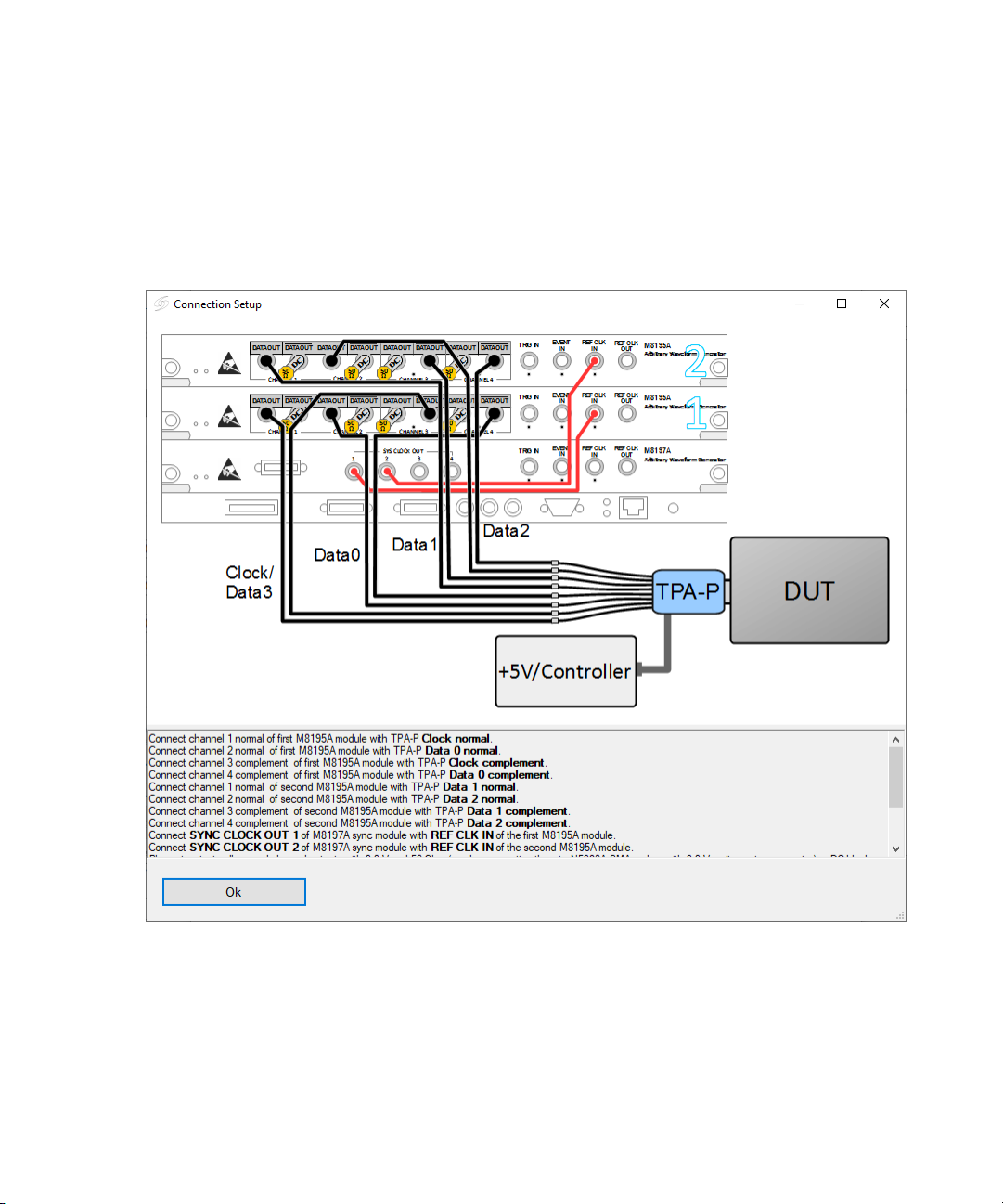
M8195A Two Module setup
This setup consists of two M8195A 2-channel modules and a M8197A
multi-channel synchronization module.
Figure 2 Connection diagram for an M8195A two module setup

12 Keysight N5991 HDMI Frame Generator User Guide
2 Test Instrument Setup

14 Keysight N5991 HDMI Frame Generator User Guide
3 Using the Software
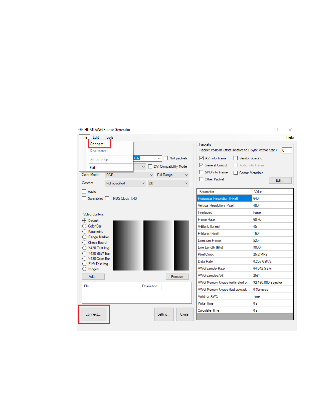
Connecting to the Instruments
After the HDMI Frame Generator is launched, the software is in “offline”
mode. This means that any user inputs remain ineffective until the
software is connected to the instruments. Click the “Connect…” button
(see Figure 3) to open the “ConnectDialog” window. Doing so enables you
to either enter or modify parameters that are necessary to establish the
connections to the signal generator and complementary instruments, such
as power supplies.
Figure 3 HDMI Frame Generator main window (Instruments in disconnected state)
Keysight N5991 HDMI Frame Generator User Guide 15
Using the Software 3
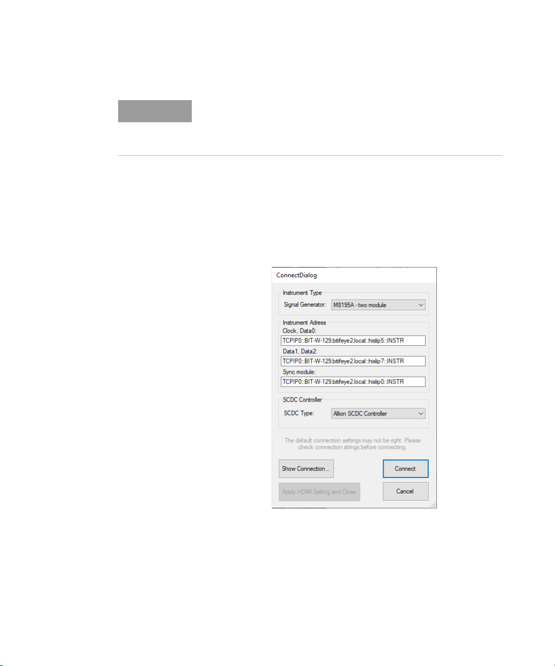
On the “ConnectionDialog” window (see Figure 4),
1 From the ‘Signal Generator’ drop-down options under “Instrument
Type”, select an AWG configuration:
•‘M8195A - single module’: if a single M8195A hardware is used.
•‘M8195A - two module’: if two M8195A and a M8197A sync module
hardware are used.
Figure 4 Connect Dialog window
2 Specify the IP address of the AWG Host PC. This is the PC, which is
connected to the hardware and runs the AWG firmwares. The default
entry “localhost” is valid, if the HDMI Frame Generator software is
residing on the controller PC of the AWG system.
NOTE
Suitable cable connections between the PC and the instruments are
required, such as LAN or USB-to-GPIB connections. The specific
connection is reflected in the name-string of the instrument. For details
on naming conventions, refer to the Keysight IO Libraries.

16 Keysight N5991 HDMI Frame Generator User Guide
3 Using the Software
3 Select and specify the modules. Each generator and the
synchronization module is specified by its VISA address, which includes
its IP address.
•For the option ‘M8195A - single module’, enter the VISA address of
the AWG module to the “Clock, Data0” and “Data1, Data2” text
boxes, respectively. This module generates all TMDS signals.
•For the option ‘M8195A - single module’, enter the VISA address of
the first AWG module to the “Clock, Data0” text box. This module
generates TMDS Clock and TMDS Data0 signals. Enter the VISA
address of the second AWG module to the “Data1, Data2” text box.
This module generates TMDS Data1 and TMDS Data2 signals. Enter
the VISA address of the ‘M8197A synchronization module’ to the
“Sync module” text box. This module synchronizes and de-skews
both the AWG modules.
4 From the ‘SCDC Type’ drop-down options under “SCDC Controller”,
select an option:
•Total Phase Aardwark
•Allion SCDC Controller
5 Click “Show Connection...” to view the basic connection set-up for the
selected configuration.
6 After setting the desired configuration, click “Connect”. The software
checks the availability of the desired connections and, if available,
establishes the instrument connections. Once connections are
successful, the label of the “Connect” button on the main window
changes to “Set”. Also, the functionality of this button is modified;
wherein, clicking “Set” applies the selected video format (and other
such formats) to the connected instruments.
7 Unless you are an advanced AWG user and have created and loaded
customized HDMI settings individually, click “Apply HMDI Setting and
Close” to exit the “ConnectDialog” window. The necessary HDMI
settings for the AWG system are applied automatically. Note that you
must first start the AWG setup specific firmware(s) on the Host PC.
8 Click Cancel, if you wish to terminate the “ConnectDialog” window
without connecting.

Keysight N5991 HDMI Frame Generator User Guide 17
Using the Software 3
CAUTION
If no Bias-Tees are used, the M8195 hardware caters for the offsets
required by the HDMI Standard. To do so, all channels must always have
the correct terminations applied. Removing its termination or applying a
wrong termination results in the safety-disablement of the M8195A
outputs. It is very important that all channels are properly terminated and
an over-voltage condition must always be avoided. If not correctly
performed, this setup could result in damage to the M8195A hardware
and any connected instruments. Modifying connections against the
recommended setup shall be done at your own risk, but it may cause
over-voltage conditions, wrong terminations and interfere accurate
functionality of the HDMI Frame Generator software. Keysight
recommends proper adherence to every instruction regarding
connections.
18 Keysight N5991 HDMI Frame Generator User Guide
3 Using the Software
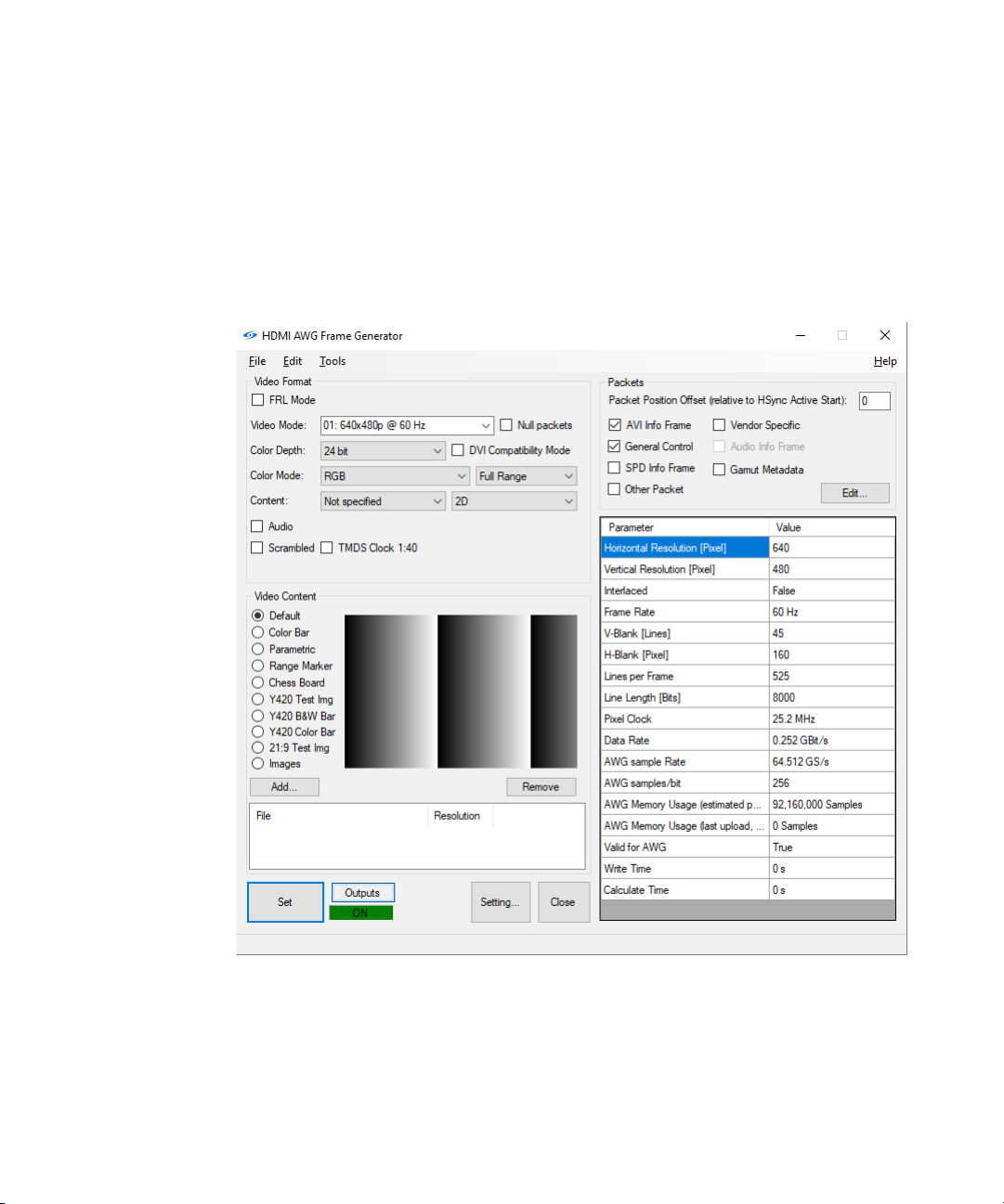
Main window
Once the connection to the instruments have been established
successfully, the main window is displayed as shown in Figure 5. It offers
basic functionality as well as access to top-level test parameters along
with the status information.
Figure 5 HDMI Frame Generator main window (Instruments in connected state)
After the parameters have been set, perform the following steps:
1 Click “Connect”. The “Connect” button initiates a dialog box that helps
in establishing a connection with the instruments, such as a signal

Keysight N5991 HDMI Frame Generator User Guide 19
Using the Software 3
generator, selected by a user. For more information, refer to
“Connecting to the Instruments” on page 14. The “Connect” button
automatically changes to the “Set” button after the Frame Generator is
connected to the instruments. Click the “Set” button to download the
pattern and set the clock frequency for the selected video mode.
2 After the Frame Generator is connected to the instruments, the
“Outputs” button appears alongside the “Set” button. Click “Outputs”
to switch On/Off the AWG outputs. If the label below this button is
Green in color, it indicates that the outputs of the AWG are switched
On, wheres, Red indicates that the AWG outputs are switched Off.
3 To download patterns, click the ‘Set Setting’ option in the “File” menu.
Once the patterns are downloaded, the “Start/Stop” button appears.
Click the “Start/Stop” button to start/stop the sequence.
4 Click the “Setting...” button to save the current settings of the Frame
Generator to a file. You may re-load this file into the Frame Generator
to assign the saved settings in the current state of the Frame
Generator software. The ‘Settings’ file is capable of containing multiple
settings. For more information, refer to Setting Dialog.
5 Click “Close” to exit the HDMI Frame Generator software.
TMDS Mode
The parameters for the TMDS Mode are shown when the FRL Mode check
box is unchecked (see Figure 4):
The properties of the video frame are divided into three sections:
1 Video Format
2Packets
3 Video Content
Video Format
The “Video Format” section in the upper part of the main window allows
you to select several parameters.
For HDMI TMDS testing, the parameters available are described in Table 1.

20 Keysight N5991 HDMI Frame Generator User Guide
3 Using the Software
Table 1 Parameters for HDMI TMDS testing
Parameters that are available for check box selections are:
• Null Packets—Check this option to fill up the blanking periods to
achieve balanced pattern.
• DVI Compatibility Mode—Check this option to enable the DVI interface,
which transfers video only.
• Audio—Audio output is accessible if supported by the hardware.
• Scrambled—HDMI 2.0 introduces scrambling to reduce EMI and to
improve the DC balancing. To send a scrambled video, select the
corresponding check box. Before performing any test using the
scrambling option, you must perform an extra step. It is necessary to
enable the scrambling in the sink using the “HDMI SCDC Controller”.
• TMDS Clock 1:40: Check this option to change the TMDS data bit rate
to 40 times the TMDS clock rate instead of 10. In the same manner as
that for Scrambling, it is necessary to use the “HDMI SCDC Controller”
to inform the sink of the relationship between the ‘TMDS clock rate’ and
the ‘TMDS data bit rate’.
Packets
To the right side of the main menu, select one or more “Info Packets”:
•AVIInfoFrame
• General Control
• SPD Info Framework
• Vendor-Specific
•AudioInfoFrame
• Gamut Metadata
• Other Packet
Parameter name Description
Video Mode Using the drop-down selection box, select the desired Video Mode from a broad choice of CEA-861 video
modes.
Color Depth Choose a Color Depth of 24, 30, 36 or 48 bits.
Color Mode You may select the Color Mode, which includes RGB as well as multiple YCbCr modes. The quantification
can be Full Range or Limited Range.
Content Select the Content flag (Not specified, Graphics, Photo, Cinema or Game) in either 2D or 3D formats
(Frame Packing, Side-by-Side (half) and Top-Bottom).
Other manuals for N5991
1
Table of contents
Other Keysight Technologies Inverter manuals

Keysight Technologies
Keysight Technologies E4360A User manual

Keysight Technologies
Keysight Technologies P9336A User guide

Keysight Technologies
Keysight Technologies 81160A User manual

Keysight Technologies
Keysight Technologies E8257D User manual

Keysight Technologies
Keysight Technologies Y1165A User manual

Keysight Technologies
Keysight Technologies 81133A User manual


