Srne HESP4860S100-H User manual

Solar Hybrid Inverter V1.0
1
Solar Hybrid Inverter
User Manual
Product models:
HESP4860S100-H

Solar Hybrid Inverter V1.0
2
Important safety instructions
Please keep this manual for future use.
This manual contains all safety, installation and operating instructions for the HESP Series all-in-one
solar charge inverter.
Please read all instructions and precautions in the manual carefully before installation and use.
Non-safety voltage exists inside the all-in-one solar charge inverter. To avoid personal injury, users
shall not disassemble the all-in-one solar charge inverter themselves. Contact our professional
maintenance personnel if there is a need for repair.
Do not place the all-in-one solar charge inverter within the reach of children.
Do not install the all-in-one solar charge inverter in harsh environments such as moist, oily,
flammable or explosive, or heavily dusty areas.
The mains input and AC output are high voltage, so please do not touch the wiring terminals.
The housing of the all-in-one solar charge inverter is hot when it is working. Do not touch it.
Do not open the terminal protective cover when the all-in-one solar charge inverter is working.
It is recommended to attach proper fuse or circuit breaker to the outside of the all-in-one solar
charge inverter.
Always disconnect the fuse or circuit breaker near the terminals of PV array, mains and battery
before installing and adjusting the wiring of the all-in-one solar charge inverter.
After installation, check that all wire connections are tight to avoid heat accumulation due to poor
connection, which is dangerous.
The all-in-one solar charge inverter is off-grid. It is necessary to confirm that it is the only input
device for load, and it is forbidden to use it in parallel with other input AC power to avoid damage.

Solar Hybrid Inverter V1.0
3
CONTENTS
1. GENERAL INFORMATION ..................................................................... 4
1.1 PRODUCT OVERVIEW AND FEATURES .................................................... 4
1.2 BASIC SYSTEM INTRODUCTION ............................................................. 4
1.3 APPEARANCE ......................................................................................5
1.4 DIMENSION DRAWING .......................................................................... 6
2. INSTALLATION INSTRUCTIONS ......................................................... 8
2.1 INSTALLATION PRECAUTIONS ................................................................8
2.2 WIRING SPECIFICATIONS AND CIRCUIT BREAKER SELECTION ................... 8
2.3 INSTALLATION AND WIRING .................................................................10
2.4 PARALLEL MACHINE WIRE CONNECTION .............................................. 17
2.4.1 Introduction ........................................................................................17
2.4.2 Precautions for connecting the parallel connecting lines .................. 17
2.4.3 Schematic diagram of parallel connection in single phase ............... 19
2.4.5 Schematic diagram of parallel connection in three phase .................22
3. OPERATING MODES .......................................................................... 28
3.1 CHARGING MODE ..............................................................................28
3.2 OUTPUT MODE ................................................................................. 29
4. LCD SCREEN OPERATING INSTRUCTIONS ................................... 30
4.1 OPERATION AND DISPLAY PANEL ........................................................30
4.2 SETUP PARAMETERS DESCRIPTION .....................................................35
4.3 BATTERY TYPE PARAMETERS ............................................................. 44
5. OTHER FUNCTIONS ...........................................................................46
5.1 DRY CONTACT .................................................................................. 46
5.2 RS485 COMMUNICATION PORT ..........................................................46
5.3 CAN COMMUNICATION FUNCTION ....................................................... 46
5.4 USB COMMUNICATION PORT ............................................................. 46
5.5 PARALLEL COMMUNICATION FUNCTION (PARALLEL OPERATION ONLY) ... 47
6. PROTECTION ...................................................................................... 47
6.1 PROTECTIONS PROVIDED ................................................................... 47
6.2 FAULT CODE ..................................................................................... 50
6.3 HANDLING MEASURES FOR PART OF FAULTS ....................................... 54
7.TROUBLESHOOTING .......................................................................... 55
8. TECHNICAL PARAMETERS ...............................................................56

Solar Hybrid Inverter V1.0
4
1. General information
1.1 Product overview and features
HESP series is a new all-in-one hybrid solar charge inverter, which integrates solar energy storage &
means charging energy storage and AC sine wave output. Thanks to DSP control and advanced control
algorithm, it has high response speed, high reliability and high industrial standard. Four charging modes
are optional, i.e. Only Solar, Mains Priority, Solar Priority and Mains & Solar hybrid charging; and two
output modes are available, i.e. Inverter and Mains, to meet different application requirements.
The solar charging module applies the latest optimized MPPT technology to quickly track the maximum
power point of the PV array in any environment and obtain the maximum energy of the solar panel in
real time.
Through a state of the art control algorithm, the AC-DC charging module realizes fully digital voltage
and current double closed loop control, with high control precision in a small volume. Wide AC voltage
input range and complete input/output protections are designed for stable and reliable battery charging
and protection.
Based on full-digital intelligent design, the DC-AC inverter module employs advanced SPWM
technology and outputs pure sine wave to convert DC into AC. It is ideal for AC loads such as
household appliances, power tools, industrial equipment, and electronic audio and video equipment.
The product comes with a segment LCD design which allows real-time display of the operating data
and status of the system. Comprehensive electronic protections keep the entire system safer and more
stable.
Features:
1. Anti-backflow grid connection function, support for inverter and mains power hybrid output,
support for use without battery, can be set up for on-grid power generation.
2. Two output modes: mains bypass and inverter output; uninterrupted power supply.
3. Available in 4 charging modes: Only Solar, Mains Priority, Solar Priority and Mains & Solar
hybrid charging.
4. Advanced MPPT technology with an efficiency of 99.9%.
5. Designed with a LCD screen and 3 LED indicators for dynamic display of system data and
operating status.
6. With time slot control, you can set the priority of using the mains and battery according to
the time slot in conjunction with the local peak and valley tariffs.
7. Power saving mode available to reduce no-load loss.
8. Intelligent variable speed fan efficiently dissipate heat and extend system life.
9. Lithium battery activation by PV solar or mains, allowing access of lead-acid battery and
lithium battery.
10. 360 ° all-around protection with a number of protection functions.
11. Complete protections, including short circuit protection, over voltage and under voltage
protection, overload protection, reverse protection, etc.
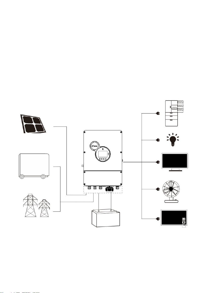
1.2 Basic system introduction
Solar Hybrid Inverter V1.0
5
The figure below shows the system application scenario of this product. A complete system consists of
the following parts:
1. PV module: Convert light energy into DC power, and charge the battery through the all-in-one
solar charge inverter, or directly invert into AC power to drive the load.
2. Mains or generator: Connected at the AC input, to power the load while charging the battery. If
the mains or generator is not connected, the system can also operate normally, and the load is
powered by the battery and PV module.
3. Battery: Provided to ensure normal power supply to the system loads when solar energy is
insufficient and the Mains is not connected.
4. Household load: Allow connection of various household and office loads, including refrigerators,
lamps, TVs, fans and air conditioners.
5. All-in-one solar charge inverter: The energy conversion unit of the whole system.
Specific system wiring method depends on the actual application scenario.
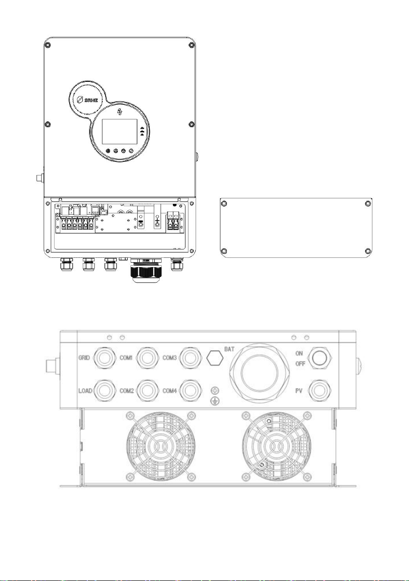
1.3 Appearance
PV array
Home Appliances
External Battery packs
Utility
Generator
or

Solar Hybrid Inverter V1.0
6
①
Indicator light
⑨
AC input
②
LCD screen
⑩
RS485-2 Communication Port
③
Touch button
⑪
USB communication port
④
PV terminal
⑫
RS485-1 Communication Port
⑤
Battery terminal
⑬
Dry-contact port
⑥
Parallel communication A port
⑭
Overload protector
⑦
Parallel communication B port
⑮
CAN communication port
⑧
AC output
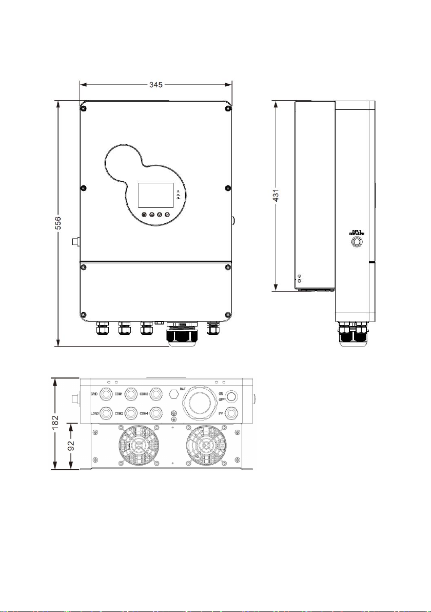
1.4 Dimension drawing
Solar Hybrid Inverter V1.0
7

Solar Hybrid Inverter V1.0
8
2. Installation instructions
2.1 Installation precautions
Please read this manual carefully prior to installation to familiarize yourself with the installation
steps.
Be very careful when installing the battery. Wear safety goggles when installing a lead-acid
liquid battery. Once coming into contact with the battery acid, rinse with clean water timely.
Do not place metal objects near the battery to prevent short-circuit of the battery.
Acid gas may be generated when the battery is charged. So, please ensure good ventilation.
When installing the cabinet, be sure to leave enough space around the all-in-one solar
charge inverter for heat dissipation. Do not install the all-in-one solar charge inverter and
lead-acid battery in the same cabinet to avoid corrosion by acid gas generated during
battery operation.
Only the battery that meets the requirements of the all-in-one unit can be charged.
Poorly connected connections and corroded wires may cause great heat which will melt the
wire insulation, burn the surrounding materials, and even cause fires. So, make sure the
connectors have been tightened, and the wires are secured with ties to avoid looseness of
connections caused by shaking of wires during mobile application.
The system connection wires are selected according to a current density of not more than 5
A/mm2.
Avoid direct sunlight and rainwater infiltration for outdoor installation.
Even after the power is turned off, there is still high voltage inside the unit. Do not open or
touch the internal components, and avoid related operations until the capacitor completely
discharges.
Do not install the all-in-one solar charge inverter in harsh environments such as moist, oily,
flammable or explosive, or heavily dusty areas.
Polarity at the battery input end of this product shall not be reversed, otherwise it may
damage the device or cause unpredictable danger.
The mains input and AC output are high voltage, so please do not touch the wiring terminals.
When the fan is working, do not touch it to prevent injury.
Load equipment input power needs to confirm that this all-in-one solar charge inverter is the
only input device, and it is forbidden to use in parallel with other input AC power to avoid
damage. It is necessary to confirm that the solar charge inverter is the only input device for
load equipment, and it is forbidden to use it in parallel with other input AC power to avoid
damage.
2.2 Wiring specifications and circuit breaker selection

Solar Hybrid Inverter V1.0
9
Wiring and installation must comply with national and local electrical codes.
Recommended PV array wiring specifications and circuit breaker selection: Since the output current of
the PV array is affected by the type, connection method and illumination angle of the PV module, the
minimum wire diameter of the PV array is calculated according to its short-circuit current; refer to the
short-circuit current value in the PV module specification (the short-circuit current is constant when the
PV modules are connected in series; the short-circuit current is the sum of the short-circuit currents of
all PV modules connected in parallel); the short-circuit current of the PV array shall not exceed the
maximum input current.
Refer to the table below for PV input wire diameter and switch:
Models
Recommended PV
wiring diameter
Maximum PV
input current
Recommended circuit
breaker type
HESP4860S100-H
6mm2/10AWG
22A
2P—25A
Note: The voltage in series shall not exceed the maximum PV input open circuit voltage.
Refer to the table below for recommended AC input wire diameter and switch:
Models
Recommended AC
input wiring diameter
Maximum bypass
input current
Recommended circuit
breaker type
HESP4860S100-H
10mm2/7AWG
40A
2P—40A
Note: There is already an appropriate circuit breaker at the Mains input wiring terminal, so it is not
necessary to add one more.
Recommended battery input wire diameter and switch selection
Models
Recommended
battery wiring
diameter
Rated battery
discharge
current
Maximum
charge
current
Recommended
circuit breaker type
HESP4860S100-H
30mm2/2AWG
135A
100A
2P—160A
Recommended AC output wiring specifications and circuit breaker selection

Solar Hybrid Inverter V1.0
10
Models
Recommended
AC output wiring
diameter
Rated inverter
AC output
current
Maximum
bypass output
current
Recommended
circuit breaker type
HESP4860S100-
H
10mm2/7AWG
26A
40A
2P—40A
Note: The wiring diameter is for reference only. If the distance between the PV array and the all-in-one
solar charge inverter or the distance between the all-in-one solar charge inverter and the battery is
relatively long, using a thicker wire can reduce the voltage drop to improve system performance.
Note: The above are only recommended wiring diameter and circuit breaker. Please select the
appropriate wiring diameter and circuit breaker according to actual situations.
2.3 Installation and wiring
Installation steps::
Step 1: Determine the installation position and the space for heat dissipation. Determine the installation
position of the all-in-one solar charge inverter, such as wall surface; when installing the all-in-one solar
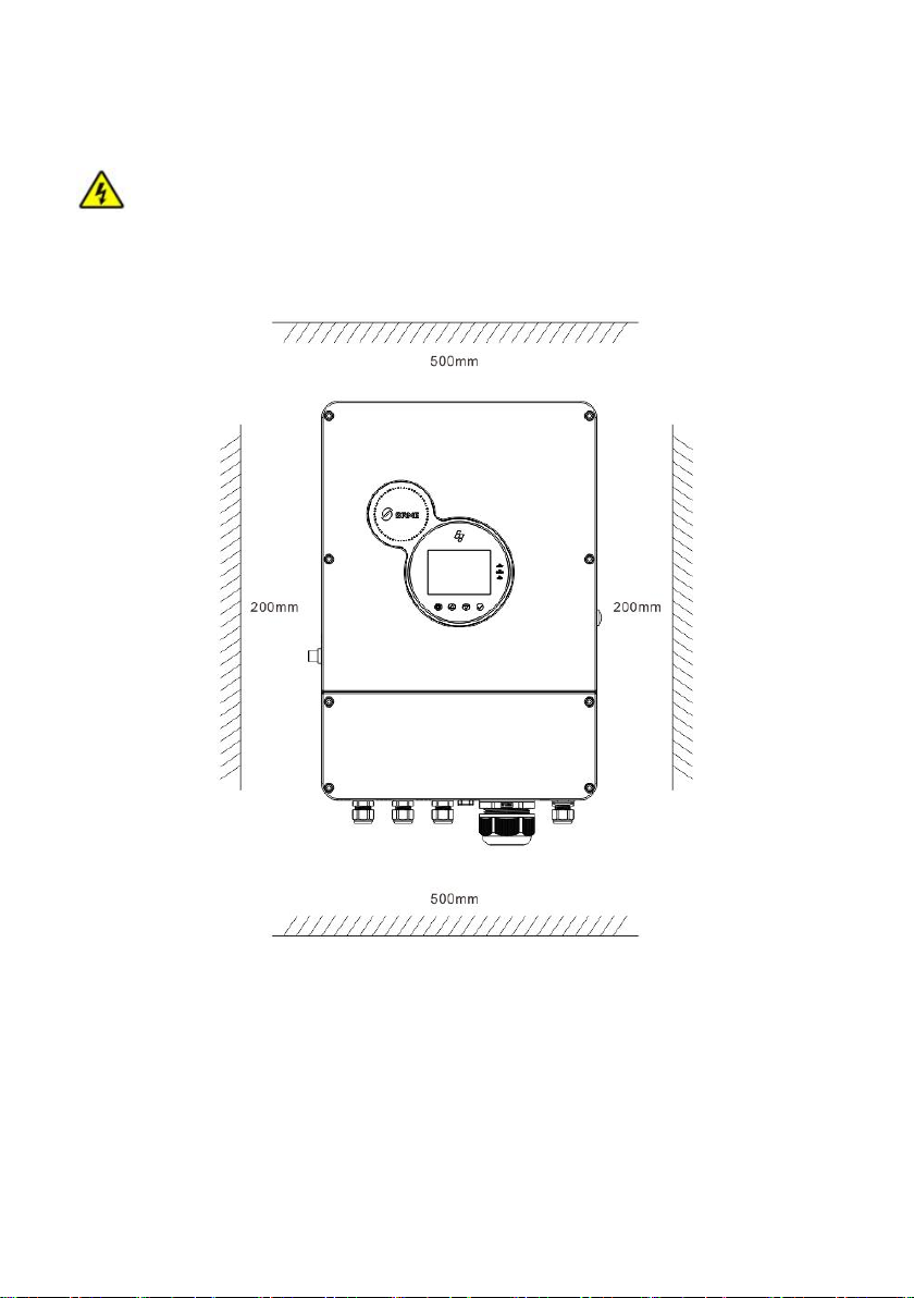
Solar Hybrid Inverter V1.0
11
charge inverter, ensure that there is enough air flowing through the heat sink, and space of at least
200m m to the left and right air outlets of the inverter shall be left to ensure natural convection heat
dissipation. Refer to the installation diagram of the whole machine as above.
Warning: Danger of explosion! Never install the all-in-one solar charge inverter and lead-acid
battery in the same confined space! Also do not install in a confined place where battery gas may
collect.
Step 2: Open 4 holes in the wall according to the following dimensions, and knock in expansion
screws, as shown in the following figure:

Solar Hybrid Inverter V1.0
12
Step 3: Hang up the machine and tighten the screws.
Step 4: Remove the terminal cover
Solar Hybrid Inverter V1.0
13
Step5: Connect the Wire. (Note: The wire shall penetrate into the corresponding joint before
crimping the terminal.)
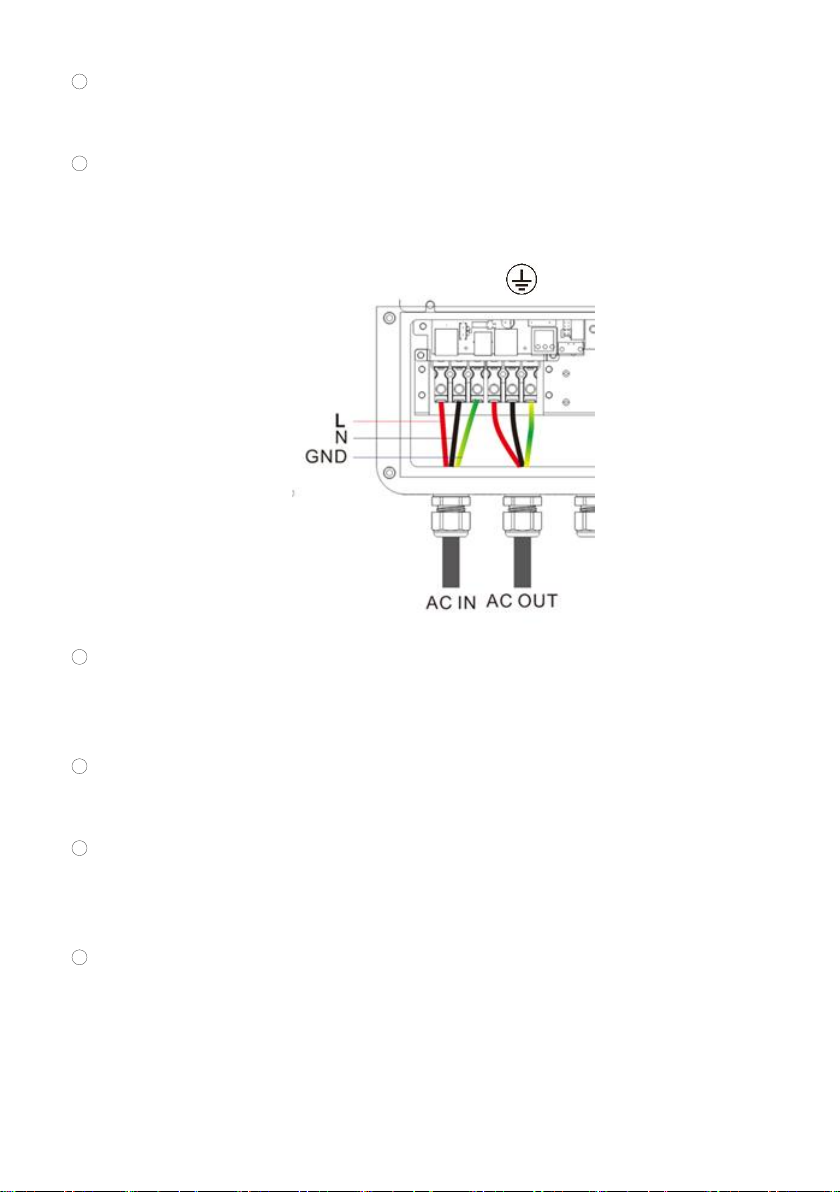
Connection method of AC I/O:
Solar Hybrid Inverter V1.0
14
1Prior to AC I/O wiring, disconnect the external circuit breaker and confirm whether the
cable used is thick enough. Please refer to Chapter "2.2 Wiring Specification and Circuit
Breaker Selection";
2According to the cable sequence and terminal position shown in the following figure,
connect the AC input line properly, please connect the grounding wire first, then connect
the live wire and the neutral wire;
L: Live Wire N: Neutral Wire : Ground Wire
3Connect the AC output line properly according to the cable sequence and terminal position
shown in the above figure. Please connect the ground wire first, then the live wire and the
neutral wire.
Wiring Method of PV Input:
1Prior to wiring, disconnect the external circuit breaker and confirm whether the cable used
is thick enough. Please refer to Chapter "2.2 Wiring Specification and Circuit Breaker
Selection";
2According to the cable sequence and terminal position shown in the following figure,
connect the PV input line properly.
BAT Wiring Method:
1Prior to wiring, disconnect the external circuit breaker and confirm whether the cable used
is thick enough. Please refer to Chapter "2.2 Wiring Specification and Circuit Breaker
Selection". BAT wire shall be connected with the machine through O-terminal. It is
recommended to use O-terminal with inner diameter of 7MM. The O-terminal must firmly
compress BAT wire to prevent excessive heating caused by excessive contact impedance;

Solar Hybrid Inverter V1.0
15
2According to the cable sequence and terminal position shown in the following figure,
connect the BAT wire properly.
Ground Wire of the Entire Machine:
As shown in the following figure, it is located on the bottom of the chassis and shall be be
connected by O-terminal. It is recommended to use O-terminal with inner diameter of 6MM.
Note: As far as possible, the ground cable should be much thicker as possible (the sectional
area of wire should not be less than 4mm2), and the grounding point should be kept close to the
Inverter as possible. The ground wire shall be shorter as possible.
Warning:
1Please be sure to disconnect the circuit breaker or fuse prior to wiring, since the mains
input, AC output and PV array will generate high voltage;
2Pay attention to safety in the process of wiring; Do Not close the circuit breaker or fuse,
and ensure the "+" and "-"pole leads of each component be connected properly in the
process of wiring; the circuit breaker must be installed at the battery end. Please refer to
Solar Hybrid Inverter V1.0
16
Chapter 2.2 “Wiring Specification and Circuit Breaker Selection” for their selection;
prior to wiring, please be sure to disconnect the circuit breaker to prevent strong electric
spark in the process of wiring and avoid short-circuiting the battery in the process of wiring; if
the inverter is applied in any area with frequent lightning, it is recommended to install an external
surge protection device at PV input.
Step 6: Check whether wires are connected properly and firmly, especially check whether
the positive and negative of the battery input are reversely connected, whether the positive and
negative of PV input are reversely connected and whether the AC input is improperly connected
to the AC output.
Step 7: Tighten the waterproof joint cover and close the machine cover back.
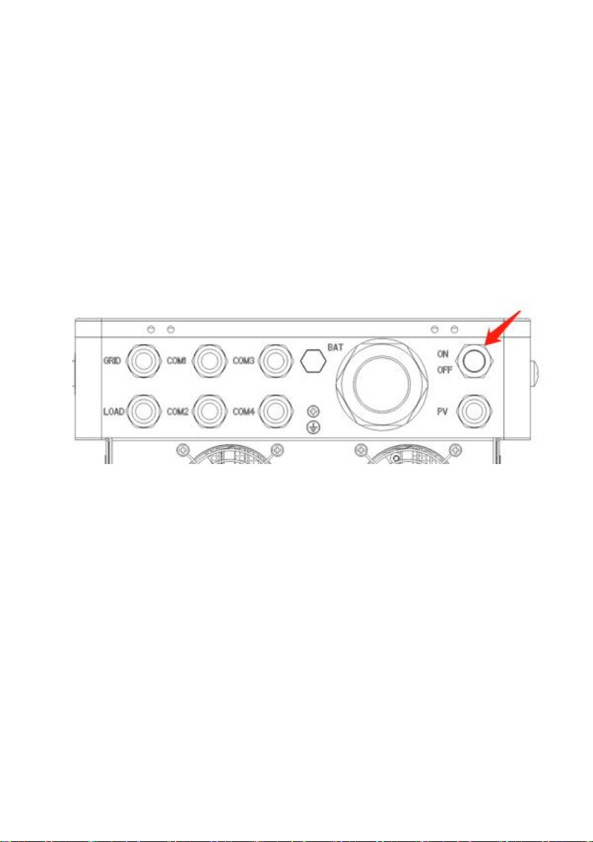
Step 8: Start the inverter
First close the circuit breaker at the battery end, then press the circular ON/OFF switch on
the right of the machine.
The flashing of "AC/INV" indicator lamp indicates that the inverter works normally. Close the
circuit breaker of PV array and Mains Power again. Finally, open the AC load one by one after
the AC output is normal so as to avoid protection action caused by major instantaneous impact
caused by opening the load at the same time and ensure that the inverter work normally in the
preset mode.
Note: If power is supplied to different AC loads, it is recommended to turn on the load with
high impulse current first, and then turn on the load with small impulse current till the load can
work stably.
Note: If the inverter is not working properly or the LCD or indicator light displays abnormally,
please refer to Chapter 6 for troubleshooting.

Solar Hybrid Inverter V1.0
17
2.4 Parallel machine wire connection
2.4.1 Introduction
1. Up to six units connected in parallel.
2. When using the parallel operation function, the following connecting lines (package
accessories) shall be firmly and reliably connected:
Parallel communication line*1:
2.4.2 Precautions for connecting the parallel connecting lines
Warning:
1. PV connection:
When used in parallel connection, different machines need to be connected to different PV
arrays or PV sources.
2. Battery wiring:
Parallel connection in single or three-phase: Ensure that all all-in-one solar charger inverters
are connected to the same battery, with BAT + connected to BAT + , BAT - connected to
BAT -, and that the connection is correct with the same wiring length and line diameter
before power on and start-up, so as to avoid the abnormal operation of parallel system
output caused by wrong connection.
3. AC OUT wiring:
Parallel connection in single phase: Ensure L-to-L, N-to-N and PE-to-PE connection for all
all-in-one solar charger inverters, and that the connection is correct with the same wiring
length and line diameter before power on and start-up, so as to avoid the abnormal operation
of parallel system output caused by wrong connection. For specific wiring, please refer to
2.4.3 Wiring Diagram
Parallel connection in three-phase: Ensure N-to-N and PE-to-PE connection for all all-in-one

Solar Hybrid Inverter V1.0
18
solar charger inverters. The Llines of all inverters connected to the same phase need to be
connected together. But Llines of different phases cannot be joined together. Other
connection precautions are the same as parallel connection in single phase. For specific
wiring, please refer to 2.4.4Wiring Diagram
4. AC IN wiring:
Parallel connection in single phase: Ensure L-to-L, N-to-N and PE-to-PE connection for all
all-in-one solar charger inverters, and that the connection is correct with the same wiring
length and line diameter before power on and start-up, so as to avoid the abnormal operation
of parallel system output caused by wrong connection. Meanwhile, it is not allowed to have
multiple different AC source inputs to avoid damage to the external equipment of the inverter.
The consistency and uniqueness of AC source input shall be ensured. For specific wiring,
please refer to 2.4.3 Wiring Diagram.
Parallel connection in three-phase: Ensure N-to-N and PE-to-PE connection for all all-in-one
solar charger inverters. The Llines of all inverters connected to the same phase need to be
connected together. But Llines of different phases cannot be joined together. Other
connection precautions are the same as parallel connection in single phase. For specific
wiring, please refer to 2.4.4 Wiring Diagram.
5. Wiring of parallel communication line:
Parallel connection in single or three-phase: Our company's parallel communication line is a
DB15 standard computer cable with shielding function. Ensure the "one-in-one-out" rule
when connecting each inverter, that is, connect the male connector (out) of this inverter with
the female connector (in) of the inverter to be paralleled. Do not connect the male connector
of the inverter to its female connector. In addition, make sure to tighten the parallel
communication line of each inverter with self-contained end screws of DB15 to avoid the
abnormal operation or damage of the system output caused by the falling off or poor contact
of the parallel communication line.
6. Wiring of current sharing detection line:
Parallel connection in single phase: Our company's current sharing detection line is a twisted
connection line. Ensure the "one-in-one-out" rule when connecting each inverter, that is,
connect the current sharing line of the inverter with the current sharing green port of the
inverter to be paralleled (choose one port from the two, and there is no mandatory sequence
requirement). The current sharing ports of the inverter cannot be connected to each other. In
addition, make sure that the red and black current sharing connection lines of each inverter

Solar Hybrid Inverter V1.0
19
are not manually exchanged, and make sure to tighten the lines with self-contained screws to
avoid the abnormal operation or damage of the system output caused by abnormal parallel
current sharing detection. For specific wiring, please refer to 2.4.3 Wiring Diagram.
Parallel connection in three-phase: The current sharing detection lines of all inverters
connected to the same phase need to be connected together. But the current sharing
detection lines of different phases cannot be joined together. Other connection precautions
are the same as parallel connection in single phase. For specific wiring, please refer to 2.4.4
Wiring Diagram.
7. Before or after connecting the system, please carefully refer to the following system wiring
diagram to ensure that all wiring is correct and reliable before power on.
8. After the system is wired, powered on and in normal operation, if a new inverter needs to be
connected, make sure to disconnect the battery input, PV input, AC input and AC output, and
that all all-in-one solar charger inverters are powered off before reconnecting into the system.
2.4.3 Schematic diagram of parallel connection in single phase
1. The parallel communication line and current sharing detection line of the all-in-one solar
charger inverter need to be locked with screws after connecting. The schematic diagram is
as follows:
2. In case of parallel operation with multiple inverters, the schematic diagram of parallel
connection is as follows:
a)Two all-in-one solar charger inverters of the system connected in parallel:

Solar Hybrid Inverter V1.0
20
b)Three all-in-one solar charger inverters of the system connected in parallel:
Table of contents
Other Srne Inverter manuals

Srne
Srne HFP4850S80-H User manual

Srne
Srne HT4830S80-145 User manual

Srne
Srne ASF4880U180-H User manual

Srne
Srne IU Series User manual

Srne
Srne ASF4880SH3 User manual

Srne
Srne HFP4850S80-145 User manual

Srne
Srne HES4855S100-H User manual

Srne
Srne HES4840S100-H User manual

Srne
Srne BP Series User manual

Srne
Srne HF2420S40-75 User manual

Srne
Srne HT4825U80 -145 User manual

Srne
Srne MC Series User manual

Srne
Srne HF4830S80-145 User manual

Srne
Srne HES4880S200-H User manual

Srne
Srne HYP4850S100-H User manual

Srne
Srne ASF4880S180-H User manual

Srne
Srne HF4825U80-145 User manual

Srne
Srne HESP Series User manual

Srne
Srne HF2430S80-H User manual

Srne
Srne HF2420U60-100 User manual


