CARPOINT 0510350 User manual

OWNER’S MANUAL
MODIFIED INVERTER
• Special features
• Fuse: External
• USB: 5V, 2.1A
• Modied sine wave output
• High reliability and high efciency
• High load capacity
• Temperature-controlled Cooling Fan
• Protection: Overload, Short Circuit, Reverse Polarity,
Over/Under Input Voltage, Overheating
• LED Indicator Inverter, Fault mode
• CE and RoHS Approved
Congratulations and thank you for purchasing this Power Inverter. Please ensure
that you read, understand and comply with all instructions before use.
EN
This is a generic multi-item manual. Images may differ from exact model.
0510350-62i_A5.indd 10510350-62i_A5.indd 1 08-07-2020 08:1008-07-2020 08:10

1. INTRODUCTION
1.1 What is an inverter?
A power inverter is an electronic device that converters low voltage DC (Direct Current) electricity from a battery or other power source to
100V-120V or 220V – 240V AC (Alternating Current) household power. DC is the power produced by a battery or other power source, while AC
is the standard power needed to run electrical equipment. A power inverter does the opposite of a rectier and is used in places and
situations in which AC power is not available.
1.2 Select the correct waveform
Modied Sine Wave: If your equipment can accept some voltage uctuations, consider a modied sine wave inverter. These inverters provide
mobile power at a more affordable price and come in a full range of sizes, from handheld to high performance. Do not use to power sensitive
devices such as medical equipment or computers. Some audio equipment may perform poorly if run on Modied Sine Wave power.
2. MAIN COMPONENTS
2.1 Front panel
The front panel view shows the inverter’s ON/OFF Switch, AC outlet, LED indicator light, Vent Outlet, USB.
A ON/OFF Switch
This switch controls the inverter’s ON/OFF operations
B. LED Indicator Light
Two LED indicator lights: Inverter, Fault
a)Inverter; this light will illuminate continuously when connected equipment is receiving battery-supplied, inverted AC Power
b)Fault: a Red light indicates a fault. Please refer to Troubleshooting
C. AC Outlet
0510350-62i_A5.indd 20510350-62i_A5.indd 2 08-07-2020 08:1008-07-2020 08:10

absOutlet sockets available for North America, Europe (Schuko), UK, Australia, etc.
AC Output Optional:
D. Vent Outlet
To reduce the inverter temperature.
E. USG Port: 5V, 2.1A
Powers and charges USB-enabled devices.
F. Remote Switch Port (Optional)
Use to connect the remote ON/OFF switch via a communications cable.
2.2 Rear Panel
The rear panel view shows the inverter’s Cooling fan, DC Battery Terminals and Fuse.
A. Cooling fans/Ventilation Windows
The fans operate automatically when the inverter’s internal temperature exceeds 45°C and requires cooling. Always allow free air ow – do
not block the vents.
B. DC Battery Terminals
Connect the inverter to a battery or other power sources.
Negative (-) and Positive (+) DC terminals should be kept insulated to protect against accidental short circuits.
a) Connect the black cable to the black post marked (-) on the back of the inverter. Connect the other end to the negative terminal on the
battery.
b) Connect the red cable to the red post marked (+) on the back of the inverter. Connect the other end to the positive terminal on the battery.
If you connect the cables to the incorrect terminals, you will reverse the polarity and damage the inverter.
REVERSE POLARITY PROHIBITED.
DAMAGE CAUSED BY REVERSE POLARITY IS NOT COVERED BY THE WARRANTY.
C. Fuse
The good design of the external fuse enables the fuse to be changed outside the inverter if the inverter fuse blows.
0510350-62i_A5.indd 30510350-62i_A5.indd 3 08-07-2020 08:1008-07-2020 08:10

3. HOW TO USE INVERTER
3.1 Positioning the inverter
The location at which the inverter is installed must be:
A. Dry: Do not allow water to drip or splash onto it.
B. Cool: The ambient air temperature should be between 0° C and 40° C - ideally between 15° C and 25° C. Do not place the inverter on or near
a heating vent or any item of equipment that generates heat above room temperature. Do not place the inverter in direct sunlight.
C. Ventilated: Allow at least one inch of clearance around the unit for air ow. Do not place items on or over the inverter during operation. Make
sure that air is allowed to circulate freely around the unit. A fan is helpful when the inverter is operating at maximum capacity.
D. Safe: Do not install the inverter in the same compartment as the batteries or in any compartment in which ammable liquids or fumes may be
present or may become present.
E. Dust: Do not install the inverter in dusty environments. Dust may be drawn into the unit when the cooling fan is operating.
F. Close to batteries: Avoid excessive cable lengths. Do not install the inverter in the same compartment as batteries.
3.2 Mounting position of the inverter
The inverter may be mounted horizontally above a horizontal surface or below a horizontal surface. The inverter may be mounted on a vertical
surface only horizontally.
3.3 Getting Connected
Follow these easy steps to get started.
1 . Power supply selection - The power source must come from a storage battery/batteries or a car cigarette lighter socket.
2. Connect the inverter to the power supply - Set the switches into the OFF position (both the inverter and appliances).
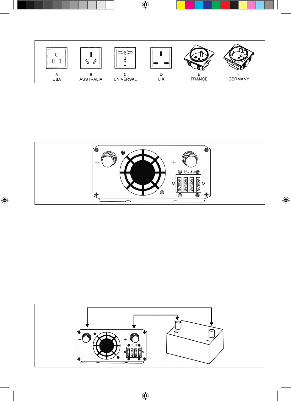
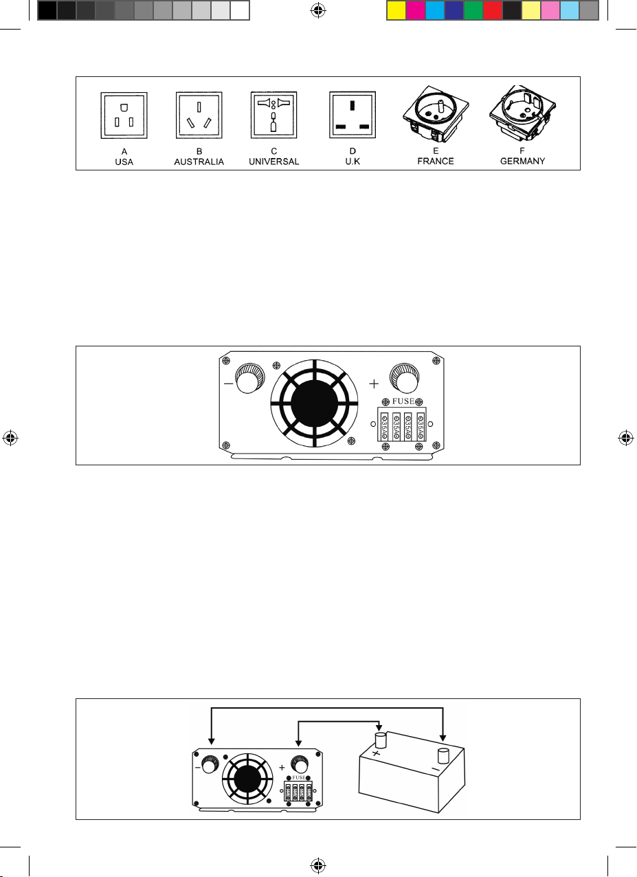
a. Power from a battery/batteries: Connect the DC cables to the DC battery terminals on the rear panel of the inverter. The red terminal is
positive (+) and the black terminal is negative(-).
b. Power from car cigarette lighter socket: insert the car cigarette lighter plug into the car cigarette lighter socket.
3. Connect inverter to appliances - Make sure the load power is within the inverter’s rated power and the start power does not exceed the
inverter’s peak power. After connecting the inverter to the appliances and a power supply, switch on the inverter and appliances. If you are
operating several loads from the power inverter, switch these on one-by-one after the inverter has been switched on. This will ensure that the
power inverter does not have to deliver starting currents for all loads simultaneously.
4. IMPORTANT SAFETY INSTRUCTIONS
Incorrect installation and misuse of the inverter may result in danger to the user or hazardous conditions.
1. Do not attempt to connect to any other power source, including an AC power source .
2. Make sure the ventilation fan and vent holes are not blocked.
3. Avoid pulling on the cords and cables. Always grip plugs rmly when unplugging from the power source and when disconnecting cables.
4. To avoid electrical hazard, unplug the inverter from its external power source before inserting the AC plug.
5. For indoor use only. Avoid exposure to external heat sources, direct prolonged sunlight, dust, corrosive chemicals and moisture.
6. It is normal for inverters to become warm during use. Avoid touching the device during use. Avoid placing in direct sunlight or near heat-sen-
sitive materials.
7. Do not drop or subject the inverter to undue shock
8. Do not place anything on top of the inverter.
9. Always use the supplied cables and connectors as indicated. Use of cables, connectors, or accessories not supplied with this product consti-
tutes misuse and may result in injury or damage.
10. Do not attempt to service or disassemble the inverter. The unit is not user-serviceable. Attempting to disassemble or service the unit may re-
sult in electrical hazard, including death from exposure to high voltage. If you experience problems with the unit, discontinue use and contact
a Technician.
11. When cleaning the inverter, please switch off the power(unplug the inverter). Clean carefully with a dry cloth. Do not use a wet cloth or
cleaning agent.
12. Disconnect all AC and DC side connections before working on any circuits associated with the inverter. Switching the inverter ON/OFF switch
to the off position may not entirely remove dangerous voltage.
13. Keep away from children.
5. PROTECTION FEATURES
The inverter is equipped with numerous protection features to ensure safe operation.
Input Low Voltage Protection
A: When battery voltage is below 10.5V± 0.5V (for 12V input inverter)/21V± 1.OV (for 24V input inverter)/42V ± 2.0V (for 48V input inverter), a
buzzer will sound indicating that the DC power supply voltage is decreasing and the batteries need to recharge.
B: When input voltage is below 1OV ± 0.5V (for 12V input inverter)/20V ± 1.OV (for 24V input inverter)/40V ± 2.0V (for 48V input inverter), the AC
output will shut off automatically, a buzzer alarm will sound and the ALARM/WARNING light will turn red.
Input Over Voltage Protection
When input voltage reaches 16.0V ± 0.5V (for 12V input inverter)/32V ± 1.OV (for 24V input inverter)/64V ± 2.0V (for 48V input inverter), the
ALARM/WARNING light will turn red and the AC output will shut off automatically.
Short Circuit Protection
When short circuits occur, the output will be shut off and the ALARM/WARNING light will turn red.
Overload Protection
When overloads occur, the output will be shut off and the ALARM/WARNING light will turn red.
Reverse polarity protection
0510350-62i_A5.indd 40510350-62i_A5.indd 4 08-07-2020 08:1008-07-2020 08:10

When battery terminals are reverse connected, the fuse will blow to protect appliances.
Overheat Protection
When the heat sink temperature exceeds 45°C, the inner cooling fan will switch on automatically to cool the inverter.
When the internal temperature exceeds 70°C, the AC output will shut off automatically and the ALARM/WARNING light will turn red. The unit
will be unusable for 15 minutes.
6. TROUBLESHOOTING REFERENCE
Acoustic buzzer alarms
When using the inverter with acoustic devices, some inferior acoustic devices will buzz, as the output wave from the inverter is a modied
sine wave inverter.
TV Interference
You can reduce interference to a minimum by using a lter. On occasions when the interference of weak signals becomes too obvious, you
can try the following:
• Place the inverter some distance away from the TV and TV antenna.
• Try to change the direction of the TV signal cable and TV antenna to reduce interference to a minimum.
• Use a high-quality screen cable antenna.
Problem: No output voltage
POSSIBLE CAUSES SOLUTION
Battery voltage too low Recharge or replace the battery
Overload Reduce the load
Inverter thermal protection Cool the inverter and position it in a well-ventilated area; Reduce the load
Inverter start-up fail Try starting the inverter again
Reverse polarity connection and fuse melted Replace the fuse with a fuse of equivalent value
Problem.· Inverter no response
POSSIBLE CAUSES SOLUTION
Poor contact between battery and inverter Reconnect the battery and inverter
Reverse polarity connection and fuse melted Replace the fuse with a fuse of equivalent value
Problem.· Output voltage low
POSSIBLE CAUSES SOLUTION
Input voltage too low Make sure the input voltage is within the rated range.
Overload Reduce the load
Problem.· Low voltage alarm
POSSIBLE CAUSES SOLUTION
Battery no power Recharge the battery
Battery voltage too low or poor connection Recharge the battery, check terminal connections or clean terminal with a dry cloth
7 SPECIFICATIONS
ITEMS MODEL
0510350 0510351 0510352 0510353 0510354
Continuous power 150W 300W 600W IOOOW 1500W
Surge Power 300W 600W 1200W 2000W 3000W
Dimensions (L x W x H) 120 x 100 x 50 120 x 100 x 50 150 x 100 x 55 210 x 150 x 70 310 x 150 x 70
Packing PCS/CTN 16 16 16 6 4
KGS/CTN 14.8 15.0 19.0 15.4 12.6
MEAS (L x W x H) cm 44 x 38 x 34 44 x 38 x 34 44 x 38 x 34 42 x 34 x 45 44 x 42 x 33
0510350-62i_A5.indd 50510350-62i_A5.indd 5 08-07-2020 08:1008-07-2020 08:10

Input Voltage 10.5V-1 6.0V (12V version) 21.OV-32V (24V version) 42.0V-64V (48V version)
Output Voltage 100-120VAC ±10%, 220V-240VAC ±10%
Output Frequency 50/60Hz ±10%
Efciency >80%
Output Waveform Modied Sine Wave
Protection Features Low Battery Alarm, Low Battery Shutdown, Over Voltage, Overheat,
Over Load, Short Circuit, Reverse Polarity (Fuse)
Battery Types Open & sealed lead acid battery
Note: *The specications are subject to change without prior notice in relation to further product improvements.
8. MAINTENANCE
Very little maintenance is required to keep your inverter operating properly.
You should clean the exterior periodically with a dry cloth to prevent the accumulation of dust and dirt. You should also periodically tighten the
screws on the DC input terminals.
9. WARRANTY
We guarantee this product against material and workmanship defects for a period of one year from the date of purchase by the end user.
This warranty will be considered void if the unit has been misused, altered, or damaged accidentally. We are not liable for anything that
occurs as a consequence of user error.
If the warranty period for your product has expired, the unit was damaged through misuse or incorrect installation, other warranty conditions
have not been met, or if no dated proof of purchase is available, a at fee will be charged for servicing or replacing your unit.
Appendix: Recommendations
For correct operation, the battery voltage should be between 0.9 x Vnom and 1.29 x Vnom where Vnom is 12V, 24V or 48V depending on the
model, and must be able to supply sufcient current to your inverter. The following table displays the recommended items (battery cable,
Fuse, Battery Capacity) per inverter type :
INVERTER TYPE INPUT VOLTAGE DC BATTERY CABLE FUSE BATTERY CAPACITY
150W 12V 2.5mm² (1 x Red/1 x Black) 35A x 1 ≥25 Ah
24V 2.5mm² (1 x Red/1 x Black) 20A x 1 ≥15 Ah
48V 2.5mm² (l x Red/1 x Black) 10A x 1 ≥10 Ah
300W 12V 4mm² (1 x Red/1 x Black) 35A x 1 ≥50 Ah
24V 2.5mm² (1 x Red/1 x Black) 20A x 1 ≥25 Ah
48V 2.5mm² (1 x Red/1 x Black) 10A x 1 ≥12 Ah
600W 12V 6mm² (1 x Red/1 x Black) 35A x 4 ≥100 Ah
24V 4mm² (1 x Red/1 x Black) 20A x 4 ≥50 Ah
48V 2.5mm² (1 x Red/1 x Black) 10A x 4 ≥25 Ah
1000W 12V 10mm² (1 x Red/l x Black) 35A x 4 ≥160 Ah
24V 6mm² (1 x Red/1 x Black) 20A x 4 ≥80 Ah
48V 4mm² (l x Red/1 x Black) 10A x 4 ≥40 Ah
1500W 12V 10mm² (2 x Red/2 x Black) 45A x 4 ≥250 Ah
24V 6mm²’ (2 x Red/2 x Black) 35A x 4 ≥125 Ah
48V 4mm² (2 x Red/2 x Black) 20A x 4 ≥60 Ah
0510350-62i_A5.indd 60510350-62i_A5.indd 6 08-07-2020 08:1008-07-2020 08:10

Appendix I: Battery Wiring Examples
In renewable energy systems, batteries are connected to each other in one of three ways:
• Series (voltage increases, amperage stays the same as a single battery)
• Parallel (voltage stays the same as a single battery, amperage increases)
• Series/Parallel (both voltage and amperage increase)
Series
Amp hours
Amp hours
Amp hours
Amp hours
Two strings of batteries in series are connected in parallel. The voltage increases to 48V and the amp hours increase to 400.
Amp Hours remain at
Voltage remains at
Amp hours
Amp hours
Amp hours
Amp hours
Amp hours
Amp hours
Amp hours
Amp hours
Amp hours
Amp hours
Amp hours
Amp hours
ParallelSeries/Parallel
0510350-62i_A5.indd 70510350-62i_A5.indd 7 08-07-2020 08:1008-07-2020 08:10

• Speciale functie
• Zekering: aan buitenzijde
• USB: 5 V, 2,1 A
• Uitvoer van gemodiceerde sinusgolf
• Uiterst betrouwbaar en efciënt
• Hoge belasting
• Koelventilator met temperatuurregeling
• Bescherming: overbelasting, kortsluiting, omgekeerde polariteit, te hoge/lage
ingangsspanning, oververhitting
• Ledlampje voor omvormer-/storingsmodus
• CE- en RoHS-goedkeuring
Gefeliciteerd met uw aankoop van onze stroomomvormer. Lees alle instructies
zorgvuldig door en zorg dat u ze begrijpt en naleeft.
INSTRUCTIEBOEKJE
GEMODIFICEERDE OMVORMER
NL
Dit is een generieke handleiding voor meerdere artikelen. De afbeeldingen kunnen hierdoor
afwijken van het exacte model.
0510350-62i_A5.indd 80510350-62i_A5.indd 8 08-07-2020 08:1008-07-2020 08:10

1. INLEIDING
1.1 Wat is een omvormer?
Een stroomomvormer is een elektronisch apparaat dat een lage gelijkstroomspanning uit een accu of andere wisselstroomvoedingsbron om-
zet in 100-120 V of 220-240 V (huishoudelijke apparaten). De gelijkstroom wordt door de accu of andere voedingsbron geproduceerd, maar
de wisselstroom is de standaardvorm die nodig is om elektrische apparatuur te laten draaien. Een stroomomvormer doet het tegenovergestel-
de van een gelijkrichter en wordt gebruikt in omgevingen en situaties waarin geen wisselstroomvoeding beschikbaar is.
1.2 De juiste golfvorm selecteren
Gemodiceerde sinusgolf: overweeg een gemodiceerde sinusomvormer als u apparatuur bestand is tegen sommige spanningsschomme-
lingen. Deze omvormers bieden stroom onderweg tegen een betaalbare prijs en zijn verkrijgbaar in tal van formaten: van kleine apparaten
tot hoogwaardige systemen. Gebruik ze niet voor gevoelige apparaten, zoals medische apparatuur of computers. Sommige audioapparaten
werken mogelijk niet goed op stroom met een gemodiceerde sinusgolf.
2. BELANGRIJKSTE COMPONENTEN
2.1 Paneel aan voorzijde
Het weergave van het paneel aan de voorzijde toont de aan-uitschakelaar, de wisselstroomuitgang, het ledlampje, de ventilatieopening en
USB-poort van de omvormer.
A Aan-uitschakelaar
Deze regelt het in-/uitschakelen van de omvormer
B. Ledlampje
Twee ledlampjes: omvormer, storing
0510350-62i_A5.indd 90510350-62i_A5.indd 9 08-07-2020 08:1008-07-2020 08:10

c) Omvormer: brandt continu als aangesloten apparatuur omgekeerde wisselstroomvoeding van de accu ontvangt;
d) Storing: wordt rood als er een storing is; raadpleeg in dat geval de oplossingen voor problemen
C. Wisselstroomuitgang
Stopcontacten in Noord-Amerika, Europa (Schuko), het Verenigd Koninkrijk, Australië, enz.
Wisselstroomuitgang optioneel:
D. Ventilatieopening
Om de temperatuur van de omvormer te verlagen.
E. USB-poort: 5 V, 2,1 A
Voor het voeden en opladen van apparaten met USB-aansluiting.
F. Poort voor externe schakelaar (optioneel)
Wordt gebruikt om de externe aan-uitschakelaar aan te sluiten via een communicatiekabel.
2.2 Achterkant
De weergave van de achterkant toont de koelventilator, gelijkstroomaccuklemmen en zekering van de omvormer.
D. Koelventilatoren/ventilatieopeningen
De ventilatoren werken altijd automatisch als de interne temperatuur (hoger dan 45 °C) van de omvormer moet worden gekoeld. Zorg dat de
lucht vrij kan stromen en blokkeer de openingen niet.
E. Gelijkstroomaccuklemmen
Sluit de omvormer aan op een accu of andere voedingsbron.
Negatieve (-) en positieve (+) gelijkstroomklemmen moeten worden geïsoleerd om onbedoelde kortsluiting te voorkomen.
a) Sluit de zwarte kabel aan op de zwarte klem met de aanduiding (-) aan de achterkant van de omvormer. Sluit het andere uiteinde aan op
de negatieve accupool;
b) Sluit de rode kabel aan op de rode klem met de aanduiding (+) aan de achterkant van de omvormer. Sluit het andere uiteinde aan op de
positieve accupool.
Als u de kabels op de onjuiste klemmen aansluit, wordt de polariteit omgekeerd en de omvormer beschadigd.
OMGEKEERDE POLARITEIT IS VERBODEN
SCHADE ALS GEVOLG VAN OMGEKEERDE POLARITEIT VALT NIET ONDER DE GARANTIE.
F. Zekering
De zekering is aan de buitenzijde geplaatst. Dit goede ontwerp zorgt dat u de zekering gemakkelijk buiten de omvormer kunt vervangen als
de zekering van uw omvormer wordt opgeblazen.
0510350-62i_A5.indd 100510350-62i_A5.indd 10 08-07-2020 08:1008-07-2020 08:10

3. DE OMVORMER GEBRUIKEN
3.1 Plaatsing van de omvormer
De locatie waar de omvormer moet worden geïnstalleerd, moet aan de volgende voorwaarden voldoen:
A. Droog: laat er geen water op druppelen of spetteren;
B. Koel: de omgevingstemperatuur moet tussen 0 °C en 40 °C en idealiter tussen 15 °C en 25 °C liggen. Plaats de omvormer niet op of in de
buurt van een verwarmingsopening of apparaat dat een warmte produceert die hoger is dan de kamertemperatuur. Plaats de omvormer niet
onnodig in direct zonlicht;
C. Geventileerd: zorg voor minimaal 2,5 cm vrije ruimte rondom het apparaat om de luchtstroom te bevorderen. Plaats geen voorwerpen op
of over de omvormer wanneer deze wordt gebruikt. Zorg dat de lucht vrij rond het apparaat kan circuleren. Een ventilator is nuttig als de
omvormer op maximaal vermogen werkt;
D. Veilig: plaats de omvormer niet in hetzelfde compartiment als de accu’s of in een compartiment waar ontvlambare vloeistoffen of dampen
aanwezig zijn of kunnen ontstaan;
E. Stofvrij: installeer de omvormer niet in stofge omgevingen. De stof kan in het apparaat worden aangezogen als de koelventilator in bedrijf is;
F. In de buurt van de accu’s: vermijd onnodig lange kabels. Installeer de omvormer niet in hetzelfde compartiment als de accu’s.
3.2 Bevestigingspositie van de omvormer
De omvormer kan horizontaal op of onder een horizontaal oppervlak worden gemonteerd. De omvormer mag op een verticaal oppervlak
alleen horizontaal worden gemonteerd.
3.3 Aansluiting
Volg deze eenvoudige stappen om aan de slag te gaan.
1. Selectie van voeding: de voeding moet afkomstig zijn van een accu of van de sigarettenaansteker in een auto;
2. Sluit de omvormer aan op de voeding. Zet de schakelaars op ‘OFF’ (inclusief van de omvormer en apparaten).
a. Voeding van accu/accu’s: sluit de gelijkstroomkabels aan op de gelijkstroomaccuklemmen aan de achterkant van de omvormer. De rode
klem is positief (+) en de zwarte klem is negatief (-);
b. Voeding van sigarettenaansteker in auto: steek de stekker voor de sigarettenaansteker in de aanstekeraansluiting in de auto;
3. Sluit de omvormer aan op apparaten. Zorg dat het belastingsvermogen binnen het nominale vermogen van de omvormer valt. Het startver-
mogen mag niet hoger zijn dan het piekvermogen van de omvormer. Schakel de omvormer en apparaten in als de omvormer op de apparaten
en voeding is aangesloten. Als u de omvormer voor verschillende belastingen gebruikt, moet u deze een voor een inschakelen nadat de
omvormer is ingeschakeld. Dit zorgt ervoor dat de stroomomvormer niet de startstroom voor alle belastingen in een keer hoeft af te leveren.
4. BELANGRIJKE VEILIGHEIDSINSTRUCTIES
Onjuiste installatie en misbruik van de omvormer kunnen gevaren voor de gebruiker of gevaarlijke situaties veroorzaken.
1. Probeer het apparaat niet op een andere voedingsbron, waaronder een wisselstroomvoeding, aan te sluiten;
2. Zorg dat de opening van de ventilator en de ventilatieopeningen niet zijn geblokkeerd;
3. Trek niet aan de snoeren en kabels. Pak altijd de stekkers stevig vast als u deze uit de voedingsbron verwijdert en als u kabels ontkoppelt;
4. Voorkom elektrische gevaren en trek de stekker van de omvormer uit de externe voedingsbron voordat u de wisselstroomstekker aansluit.
5. Alleen voor gebruik binnenshuis. Vermijd blootstelling aan externe hittebronnen, direct en langdurig zonlicht, stof, corrosieve chemische
stoffen en vocht;
6. Het is normaal dat omvormers tijdens het gebruik opwarmen. Raak het apparaat niet aan tijdens het gebruik.
Plaats het niet in direct zonlicht of in de buurt van hittegevoelige materialen;
7. Laat de omvormer niet vallen en stel deze niet bloot aan grote schokken;
8. Plaats geen voorwerpen boven op de omvormer;
9. Gebruik altijd de meegeleverde kabels en stekkers. Het gebruik van kabels, stekkers of accessoires die niet bij dit product zijn geleverd, is
een vorm van misbruik en kan tot letsel of schade leiden;
10. Probeer het apparaat niet zelf te onderhouden of demonteren. Dit apparaat kan niet door de gebruiker worden onderhouden. Pogingen om het
apparaat te demonteren of onderhouden, kan tot elektrische gevaren, inclusief de dood, leiden als gevolg van blootstelling aan hoogspanning.
Stop het gebruik en neem contact op met een monteur als u problemen met het apparaat ervaart;
11. Schakel de voeding uit als u de omvormer schoonmaakt (verwijder de stekker). Maak het apparaat zorgvuldig schoon met een droge doek.
Gebruik geen natte doek of schoonmaakmiddel;
12. Verbreek alle aansluitingen aan de wisselstroom- en gelijkstroomzijde voordat u werkzaamheden uitvoert aan circuits die op de omvormer
zijn aangesloten. Als de aan-uitschakelaar op de omvormer op ‘OFF’ wordt gezet, wordt de gevaarlijke spanning mogelijk niet helemaal
afgevoerd;
13. Bewaar dit product uit de buurt van kinderen.
5. BESCHERMINGSFUNCTIE
Om veilig gebruik te garanderen, is de omvormer voorzien van talloze beschermingsfuncties.
Bescherming tegen lage ingangsspanning
A: Als de accuspanning lager dan 10,5 V ± 0,5 V (voor een omvormer met een ingang van 12 V)/21 V ± 1.0 V (voor een omvormer met een
ingang van 24 V)/42 V ± 2,0 V (voor een omvormer met een ingang van 48 V) is, zal er een zoemer klinken om aan te geven dat de ge-
lijkstroomvoedingsspanning afneemt en de accu’s moeten worden opgeladen.
B: Als de ingangsspanning lager dan 10 V ± 0,5 V (voor een omvormer met een ingang van 12 V)/20 V ± 1.0 V (voor een omvormer met een
ingang van 24 V)/40 V ± 2,0 V (voor een omvormer met een ingang van 48 V) is, zal de wisselstroomuitgang automatisch worden afgesloten,
klinkt er een zoemer en gaat het lampje ALARM/WAARSCHUWING rood branden.
Bescherming tegen hoge ingangsspanning
Als de ingangsspanning 16 V ± 0,5 V (voor een omvormer met een ingang van 12 V)/32 V ± 1.0 V (voor een omvormer met een ingang van 24
0510350-62i_A5.indd 110510350-62i_A5.indd 11 08-07-2020 08:1008-07-2020 08:10

V)/64 V ± 2,0 V (voor een omvormer met een ingang van 48 V) is, zal het lampje ALARM/WAARSCHUWING rood branden en wordt de wissel-
stroomuitgang automatisch uitgeschakeld.
Bescherming tegen kortsluiting
In geval van kortsluiting zal de uitgang worden uitgeschakeld en gaat het lampje ALARM/WAARSCHUWING rood branden
Bescherming tegen overbelasting
In geval van overbelasting zal de uitgang worden uitgeschakeld en gaat het lampje ALARM/WAARSCHUWING rood branden
Bescherming tegen omgekeerde polariteit
Als accuklemmen verkeerd worden aangesloten, zal de zekering doorbranden om de apparaten te beschermen.
Bescherming tegen oververhitting
Als de temperatuur in de warmteafvoer hoger dan 45 °C is, zal de interne koelventilator automatisch worden ingeschakeld om de omvormer
te koelen.
Als de temperatuur hoger dan 70 °C is, zal de wisselstroomuitgang automatisch worden afgesloten en wordt het lampje ALARM/WAARSCHU-
WING rood. Het apparaat kan dan 15 minuten niet worden gebruikt.
6. GIDS VOOR HET OPLOSSEN VAN PROBLEMEN
Alarmen van zoemer
Als de omvormer op akoestische apparaten wordt aangesloten, zullen sommige akoestische apparaten van slechte kwaliteit zoemen. Dit komt
doordat de uitgangsgolf van de omvormer een gemodiceerde sinusgolf is.
Storing op tv
Wanneer u een lter gebruikt, is er sprake van minimale verstoring. Als de storing van elk zwak signaal te duidelijk merkbaar wordt, kunt u
het volgende proberen:
• Plaats de omvormer ver bij de tv en tv-antenne vandaan;
• Probeer de tv-signaalkabel en tv-antenne te verplaatsen om de storing tot een minimum te beperken;
• Gebruik een kabelantenne van hoge kwaliteit.
Probleem: Geen uitgangsspanning
MOGELIJKE OORZAKEN OPLOSSING
Accuspanning te laag Laad de accu op of vervang deze
Overbelasting Verminder de belasting
Thermische bescherming van omvormer Laat de omvormer afkoelen en plaats deze in een omgeving met goede ventilatie;
verminder de belasting
Omvormer kan niet worden gestart Start de omvormer opnieuw
Omgekeerde polariteit in verbinding, zekering
gesmolten
Vervang de zekering door een zekering met een gelijke waarde.
Probleem: Omvormer reageert niet
MOGELIJKE OORZAKEN OPLOSSING
Slecht contact tussen accu en omvormer Sluit ze opnieuw aan
Omgekeerde polariteit in verbinding, zekering
gesmolten
Vervang de zekering door een zekering met een gelijke waarde
Probleem: Uitgangsspanning te laag
MOGELIJKE OORZAKEN OPLOSSING
Ingangsspanning te laag Zorg dat de ingangsspanning binnen het nominale bereik valt.
Overbelasting Verminder de belasting
Probleem: Alarm voor lage spanning
MOGELIJKE OORZAKEN OPLOSSING
De accu heeft geen vermogen De batterij opladen
De accuspanning is te laag of de accu is niet
goed aangesloten
Laad de accu opnieuw op, controleer de aansluiting van de klemmen of maak de klem
schoon met een droge doek
0510350-62i_A5.indd 120510350-62i_A5.indd 12 08-07-2020 08:1008-07-2020 08:10

7 SPECIFICATIES
ITEMS MODEL
0510350 0510351 0510352 0510353 0510354
Continue stroom 150W 300W 600W IOOOW 1500W
Piekstroom 300W 600W 1200W 2000W 3000W
Afmetingen in mm (L x B x H) 120 x 100 x 50 120 x 100 x 50 150 x 100 x 55 210 x 150 x 70 310 x 150 x 70
Verpakking Aantal stuks per doos 16 16 16 6 4
Kg/doos 12.6 15.0 19.0 17 10.5
Afmetingen in cm
(L x B x H)
44 x 38 x 34 44 x 38 x 34 44 x 38 x 34 42 x 34 x 45 44 x 42 x 33
NB: * De specicaties kunnen zonder voorafgaande kennisgeving worden gewijzigd om het product verder te verbeteren.
Ingangsspanning 10,5 V - 16,0 V (12 V-uitvoeringrsion) 2l,0 V - 32 V (24 V-versie) 42,0 V - 64 V (48 V-uitvoering)
Uitgangsspanning 100-120 VAC ± 10%, 220 V-240 VAC ± 10%
Uitgangsgolfvorm 50/60Hz ±10%
Efciëntie >80%
Uitgangsgolfvorm Gemodiceerde sinusgolf
Beschermingsfunctie Alarm voor lege accu, uitschakeling bij lege accu, overspanning, oververhitting,
overbelasting, kortsluiting, omgekeerde polariteit (zekering).
Accutypen Open en gesloten loodzuuraccu
NB: * De specicaties kunnen zonder voorafgaande kennisgeving worden gewijzigd om het product verder te verbeteren.
8. ONDERHOUD
Er is heel weinig onderhoud nodig om te zorgen dat uw omvormer goed blijft werken.
Maak de buitenkant regelmatig schoon met een droge doek om ophoping van stof en vuil te voorkomen. Draai de schroeven van de ge-
lijkstroomingangsklemmen aan.
9. GARANTIE
We garanderen dat dit product gedurende een jaar vanaf de datum van aankoop door de eindgebruiker vrij is van defecten in materialen en
vakmanschap.
Deze garantie zal vervallen als het apparaat verkeerd wordt gebruikt, wordt aangepast of per ongeluk wordt beschadigd. We zijn niet aan-
sprakelijk voor situaties die het gevolg zijn van fouten door de gebruiker.
Als de garantieperiode voor ons product is verstreken, als het apparaat werd beschadigd als gevolg van foutief gebruik of onjuiste installatie,
als er niet aan andere garantievoorwaarden is voldaan of als er geen aankoopbewijs met datum kan worden aangetoond, kan uw apparaat
mogelijk worden onderhouden of vervangen tegen een vast bedrag.
0510350-62i_A5.indd 130510350-62i_A5.indd 13 08-07-2020 08:1008-07-2020 08:10

Bijlage: Aanbeveling
Om het apparaat goed te laten werken, moet de accuspanning tussen 0,9x Vnom en 1,29x Vnom liggen, waarbij Vnom 12 V, 24 V of 48 V is
(afhankelijk van het model). Ook moet er voldoende stroom voor uw omvormer kunnen worden geboden. De volgende tabel geeft aanbevolen
zaken (accukabel, zekering, accuvermogen) per type omvormer weer:
TYPE OMVORMER INGANGSSPANNING GELIJKSTROOMACCUKABEL ZEKERING ACCUVERMOGEN
150W 12V 2.5mm² (1 x rood/1 x zwart) 35A x 1 ≥25 Ah
24V 2.5mm² (1 x rood/1 x zwart) 20A x 1 ≥15 Ah
48V 2.5mm² (l x rood/1 x zwart) 10A x 1 ≥10 Ah
300W 12V 4mm² (1 x rood/1 x zwart) 35A x 1 ≥50 Ah
24V 2.5mm² (1 x rood/1 x zwart) 20A x 1 ≥25 Ah
48V 2.5mm² (1 x rood/1 x zwart) 10A x 1 ≥12 Ah
600W 12V 6mm² (1 x rood/1 x zwart) 35A x 4 ≥100 Ah
24V 4mm² (1 x rood/1 x zwart) 20A x 4 ≥50 Ah
48V 2.5mm² (1 x rood/1 x zwart) 10A x 4 ≥25 Ah
1000W 12V 10mm² (1 x rood/l x zwart) 35A x 4 ≥160 Ah
24V 6mm² (1 x rood/1 x zwart) 20A x 4 ≥80 Ah
48V 4mm² (l x rood/1 x zwart) 10A x 4 ≥40 Ah
1500W 12V 10mm² (2 x rood/2 x zwart) 45A x 4 ≥250 Ah
24V 6mm²’ (2 x rood/2 x zwart) 35A x 4 ≥125 Ah
48V 4mm² (2 x rood/2 x zwart) 20A x 4 ≥60 Ah
Bijlage I: Voorbeelden van accukabels
In systemen met hernieuwbare energie worden accu’s op een van de drie volgende manieren met elkaar verbonden:
• Serieel (spanning neemt toe, stroomsterkte blijft identiek aan die van een accu);
• Parallel (spanning blijft hetzelfde als die van een accu, stroomsterkte neemt toe);
• Serieel/parallel (zowel spanning als stroomsterkte neemt toe)
Serieel
Ampère-uur
Ampère-uur
Ampère-uur
Ampère-uur
Twee reeksen seriële accu’s zijn parallel geschakeld. De spanning neemt toe tot 48 V en de ampère-uur neemt toe tot 400.
Ampère-uur blijft
Spanning blijft
Ampère-uur
Ampère-uur
Ampère-uur
Ampère-uur
Ampère-uur
Ampère-uur
Ampère-uur
Ampère-uur
Ampère-uur
Ampère-uur
Ampère-uur
Ampère-uur
ParallelSerieel/parallel
0510350-62i_A5.indd 140510350-62i_A5.indd 14 08-07-2020 08:1008-07-2020 08:10

• Caractéristiques spéciales
• Fusible : non intégré
• USB : 5 V, 2,1 A
• Sortie de l’onde sinusoïdale modiée
• Grande abilité et efcacité supérieure
• Capacité de charge élevée
• Ventilateur de refroidissement à température contrôlée
• Protection : surcharge, court-circuit, polarité inversée,
surtension/sous-tension d’entrée, surchauffe
• Les voyants à DEL indiquent les modes Onduleur et Défaillance.
• Certié CE et RoHS
Nous vous félicitons et vous remercions d’avoir acheté notre onduleur. Lisez attentivement
toutes les instructions avant d’utiliser le produit, comprenez-les bien et respectez-les.
ONDULEUR MANUEL
D’UTILISATION
CONVERTISSEUR MODIFIÉE
FR
Mode d’emploi générique applicable à plusieurs références articles,
les photos pouvant varier.
0510350-62i_A5.indd 150510350-62i_A5.indd 15 08-07-2020 08:1008-07-2020 08:10

1. INTRODUCTION
1.1 Qu’est-ce qu’un onduleur ?
Un onduleur est un appareil électronique qui convertit le courant continu (c.c.) basse tension d’une batterie ou d’une autre source d’alimen-
tation en un courant alternatif (c.a.) de 100 V-120 V ou 220 V-240 V. Le c.c. est l’électricité produite par une batterie ou une autre source
d’alimentation tandis que le c.a. est le courant électrique standard nécessaire pour faire fonctionner un équipement électrique. Un onduleur
réalise le contraire d’un redresseur et est utilisé dans les endroits et les situations où le c.a. n’est pas disponible.
1.2 Choix de la forme d’onde appropriée
Onde sinusoïdale modiée : si votre équipement peut accepter quelques uctuations de tension, envisagez un onduleur à onde sinusoïda-
le modiée. Ces onduleurs fournissent une alimentation mobile à un prix abordable et sont disponibles dans une gamme complète, des
onduleurs portables aux onduleurs hautes performances. N’utilisez pas ce type d’onde pour alimenter des appareils sensibles, comme des
équipements médicaux ou des ordinateurs. Certains équipements audio peuvent fournir de mauvaises performances s’ils fonctionnent sur
une alimentation à onde sinusoïdale modiée.
2. PRINCIPAUX COMPOSANTS
2.1 Panneau avant
Le panneau avant illustré ci-dessous représente l’interrupteur MARCHE/ARRÊT, la sortie du courant alternatif, les voyants à DEL, la sortie d’air
et le port USB de l’onduleur.
A. Interrupteur MARCHE/ARRÊT
Cet interrupteur contrôle les fonctions MARCHE et ARRÊT de l’onduleur.
B. Voyants à DEL
Deux voyants à DEL sont présents : Onduleur (INV) et Défaillance (FAULT).
0510350-62i_A5.indd 160510350-62i_A5.indd 16 08-07-2020 08:1008-07-2020 08:10

e) Onduleur : ce voyant s’allume de manière xe chaque fois que l’équipement connecté est alimenté par un courant alternatif converti
fourni par la batterie.
f) Défaillance : si ce voyant s’allume en rouge, il indique une défaillance. Reportez-vous à la section Dépannage.
C. Sortie c.a.
Prises de courant disponibles : Amérique du Nord, Europe (schuko), Royaume-Uni, Australie, etc.
Sorties c.a. optionnelles :
D. Sortie d’air
Elle permet de réduire la température de l’onduleur.
E. Port USB : 5 V, 2,1 A
Il alimente et charge les appareils compatibles USB.
F. Port de l’interrupteur à distance (en option)
Utilisez-le pour connecter l’interrupteur MARCHE/ARRÊT à distance via un câble de communication.
2.4 Panneau arrière
Le panneau arrière illustré ci-dessous représente le ventilateur de refroidissement, les bornes c.c. de la batterie et le fusible de l’onduleur.
G. Ventilateurs de refroidissement/Orices de ventilation
Les ventilateurs fonctionnent automatiquement lorsque la température transitoire de l’onduleur (supérieure à 45 °C) nécessite le refroidisse-
ment. Laissez toujours l’air circuler librement, n’obstruez pas les orices de ventilation.
H. Bornes c.c. de la batterie
Connectez l’onduleur à la batterie ou à une autre source d’alimentation.
Les bornes c.c. négative (-) et positive (+) doivent rester isolées an d’éviter tout court-circuit accidentel.
a) Branchez le câble noir sur la borne noire indiquée (-) à l’arrière de l’onduleur.
Branchez l’autre extrémité à la borne négative de labatterie.
b) Branchez le câble rouge sur la borne rouge indiquée (+) à l’arrière de l’onduleur.
Branchez l’autre extrémité à la borne positive de la batterie.
Si vous branchez les câbles sur les mauvaises bornes, vous inverserez la polarité et endommagerez l’onduleur.
INTERDICTION D’INVERSER LA POLARITÉ
LES DOMMAGES CAUSÉS PAR UNE INVERSION DE LA POLARITÉ NE SONT PAS COUVERTS PAR LA GARANTIE.
I. Fusible
La conception du fusible a été parfaitement rééchie. En effet, il n’a pas été intégré dans l’onduleur, mais placé à l’extérieur, ce qui permet de
le remplacer très facilement lorsqu’il grille.
0510350-62i_A5.indd 170510350-62i_A5.indd 17 08-07-2020 08:1008-07-2020 08:10

3. UTILISATION DE L’ONDULEUR
3.1 Emplacement de l’onduleur
Le lieu où vous installez l’onduleur doit respecter les critères suivants :
A. Sec : évitez toute goutte ou éclaboussure d’eau sur l’onduleur.
B. Frais : la température ambiante doit être comprise entre 0 °C et 40 °C, idéalement entre 15 °C et 25 °C. Ne placez pas l’onduleur sur ou à
proximité d’une bouche d’évacuation de chauffage ou d’un élément d’un équipement qui génère une chaleur supérieure à la température de
la pièce. N’exposez pas inutilement l’onduleur aux rayons directs du soleil.
C. Ventilé : laissez au moins 2,5 cm d’espace tout autour de l’appareil an que l’air puisse circuler. Ne placez rien sur ou au-dessus de l’on-
duleur pendant son fonctionnement. Assurez-vous que l’air peut circuler librement autour de l’appareil. Un ventilateur est utile si l’onduleur
fonctionne à la puissance maximale.
D. Sûr : n’installez pas l’onduleur dans le même compartiment que les batteries ou dans un compartiment contenant ou pouvant contenir des
liquides ou vapeurs inammables.
E. Propre : n’installez pas l’onduleur dans un environnement poussiéreux. La poussière peut être aspirée dans l’appareil lorsque le ventilateur de
refroidissement fonctionne.
F. À proximité des batteries : évitez toute longueur de câble excessive. N’installez pas l’onduleur dans le même compartiment que les batteries.
3.2 Position de montage de l’onduleur
L’onduleur peut être installé horizontalement sur ou sous une surface horizontale. L’onduleur peut être installé sur une surface verticale, mais
uniquement horizontalement.
3.3 Branchements
Respectez ces étapes simples pour mettre en marche l’onduleur.
1. Choix de l’alimentation électrique. L’alimentation doit provenir d’une ou de plusieurs batterie(s) rechargeable(s) ou d’un port allume-cigare
d’un véhicule.
2. Connectez l’onduleur à l’alimentation électrique. Réglez les interrupteurs sur ARRÊT (onduleur et appareils).
a. Alimentation provenant d’une/de plusieurs batterie(s) : connectez les câbles c.c. aux bornes c.c. de la batterie sur le panneau arrière de
l’onduleur. La borne rouge est positive (+) et la borne noire est négative (-).
b. Alimentation provenant d’un port allume-cigare d’un véhicule : insérez la che allume-cigare dans le port allume-cigare du véhicule.
3. Connectez l’onduleur aux appareils. Assurez-vous que la puissance de sortie est comprise dans la puissance nominale de l’onduleur et que
la puissance de démarrage ne dépasse pas la puissance de crête de l’onduleur. Une fois que l’onduleur est connecté aux appareils et à une
alimentation électrique, mettez en marche l’onduleur et les appareils. Si vous faites fonctionner plusieurs charges à partir de l’onduleur,
mettez-les en marche séparément après la mise en marche de l’onduleur. Cela garantit que l’onduleur n’ait pas à fournir les courants de
démarrage simultanément pour toutes les charges.
4. CONSIGNES DE SÉCURITÉ IMPORTANTES
Une installation incorrecte et une utilisation abusive de l’onduleur peuvent mettre en danger l’utilisateur ou générer des conditions dangereuses.
1. Ne tentez pas de connecter d’autres sources d’alimentation, y compris une source d’alimentation c.a.
2. Assurez-vous que les ouvertures du ventilateur et les orices de ventilation ne sont pas bloqués.
3. Évitez de tirer sur les cordons et les câbles. Tenez toujours fermement la che lorsque vous la débranchez d’une source électrique et lorsque
vous déconnectez les câbles.
4. Pour éviter tout risque électrique, veillez à débrancher l’onduleur de sa source d’alimentation externe avant de brancher la che c.a.
5. Pour un usage en intérieur uniquement. Évitez toute exposition à des sources de chaleur externes, toute exposition prolongée aux rayons
directs du soleil, à la poussière, aux produits chimiques corrosifs et à l’humidité.
6. Il est normal que les onduleurs chauffent pendant l’utilisation. Évitez de toucher l’appareil pendant son utilisation.
Évitez de placer l’appareil au soleil ou à proximité de matériaux sensibles à la chaleur.
7. Ne faites pas tomber l’onduleur et évitez de l’exposer à des chocs excessifs.
8. Ne placez rien au-dessus de l’onduleur.
9. Utilisez toujours les câbles et connecteurs fournis, tel qu’indiqué. Utiliser des câbles, connecteurs ou accessoires non fournis avec ce produit
constitue une utilisation abusive et peut entraîner des blessures ou des dommages.
10. Ne tentez pas d’assurer la réparation de l’appareil ou de le démonter. L’appareil ne peut pas être réparé par l’utilisateur. Tenter de démonter
ou de réparer l’appareil peut entraîner un risque électrique, y compris un décès, en raison de l’exposition à une tension élevée. Si vous
rencontrez des problèmes avec l’appareil, ne l’utilisez plus et contactez un technicien.
11. Lorsque vous nettoyez l’onduleur, éteignez-le (débranchez-le). Nettoyez-le soigneusement avec un chiffon sec. N’utilisez pas de chiffon
humide ni de produit nettoyant.
12. Débranchez toutes les connexions côtés c.a. et c.c. avant de travailler sur des circuits, quels qu’ils soient, associés à l’onduleur. Régler
l’interrupteur MARCHE/ARRÊT de l’onduleur en position ARRÊT n’écarte pas totalement les risques liés à la tension.
13. Conservez hors de portée des enfants.
5. CARACTÉRISTIQUES DE PROTECTION
L’onduleur est équipé de nombreuses fonctions de protection an de garantir un fonctionnement sûr.
Protection contre une tension d’entrée faible
A : lorsque la tension de la batterie est inférieure à 10,5 V ± 0,5 V (pour un onduleur de 12 V d’entrée)/ 21 V ± 1,0 V (pour un onduleur de 24 V
d’entrée)/ 42 V ± 2,0 V (pour un onduleur de 48 V d’entrée), une alarme se déclenche an d’indiquer que la tension d’alimentation c.c. est en
chute et que les batteries doivent être rechargées.
B : lorsque la tension d’entrée est inférieure à 10 V ± 0,5 V (pour un onduleur de 12 V d’entrée)/ 20 V ± 1,0 V (pour un onduleur de 24 V d’entrée)/
40 V ± 2,0 V (pour un onduleur de 48 V d’entrée), la sortie c.a. est automatiquement désactivée, une alarme retentit et le voyant ALARME/
AVERTISSEMENT s’allume simultanément en rouge.
0510350-62i_A5.indd 180510350-62i_A5.indd 18 08-07-2020 08:1008-07-2020 08:10

Protection contre la surtension d’entrée
Si la tension d’entrée atteint 16,0 V ± 0,5 V (pour un onduleur de 12 V d’entrée)/ 32 V ± 1,0 V (pour un onduleur de 24 V d’entrée)/ 64 V ± 2,0
V (pour un onduleur de 48 V d’entrée), le voyant ALARME/AVERTISSEMENT devient rouge et la sortie c.a. est automatiquement désactivée.
Protection contre les courts-circuits
Si un court-circuit se produit, la sortie est désactivée et le voyant ALARME/AVERTISSEMENT devient rouge.
Protection contre la surcharge
Si une surcharge survient, la sortie est désactivée et le voyant ALARME/AVERTISSEMENT devient rouge.
Protection contre la polarité inversée
Si les bornes de la batterie sont connectées de manière inversée, le fusible grille an de protéger les appareils.
Protection contre la surchauffe
Si la température du dissipateur thermique dépasse 45 °C, le ventilateur de refroidissement interne est automatiquement activé an de
refroidir l’onduleur.
Si la température interne dépasse 70 °C, la sortie c.a. est automatiquement désactivée et le voyant ALARME/AVERTISSEMENT devient rouge.
Elle ne peut pas être utilisée pendant 15 minutes.
6. DÉPANNAGE
Déclenchement de l’alarme d’appareils acoustiques
Si vous appliquez l’onduleur à des appareils acoustiques, certains appareils acoustiques inférieurs émettent une alarme. Cela est dû au fait
que l’onde de sortie de l’onduleur est une onde sinusoïdale modiée.
Interférence TV
Vous pouvez minimiser les interférences en utilisant un ltre. Dans certains cas, lorsque l’interférence de tous les signaux faibles devient trop
agrante, vous pouvez procéder
comme suit
• Placez l’onduleur loin de la télévision ou de l’antenne de la télévision.
• Essayez de changer la direction du câble des signaux de la télévision et de l’antenne de la télévision an de réduire au minimum les inter-
férences.
• Utilisez un câble d’antenne blindé de meilleure qualité.
Problème : aucune tension de sortie
CAUSES POSSIBLES SOLUTION
Tension de la batterie trop faible Rechargez ou remplacez la batterie.
Surcharge Réduisez la charge.
Protection thermique de l’onduleur Refroidissez l’onduleur et placez-le dans un lieu bien aéré. Réduisez la charge.
Échec au démarrage de l’onduleur Redémarrez l’onduleur.
Connexion en polarité inversée et fusible fondu Remplacez le fusible par un fusible de valeur équivalente.
Problème : pas de réponse de l’onduleur
CAUSES POSSIBLES SOLUTION
Mauvais contact entre la batterie et l’onduleur Reconnectez-les.
Connexion en polarité inversée et fusible fondu Remplacez le fusible par un fusible de valeur équivalente.
Problème : tension de sortie faible
CAUSES POSSIBLES SOLUTION
Tension d’entrée trop faible Vériez que la tension d’entrée est comprise dans la plage nominale.
Surcharge Réduisez la charge.
Problème : alarme signalant une tension faible
CAUSES POSSIBLES SOLUTION
Pas d’alimentation au niveau de la batterie Rechargez la batterie.
Tension de la batterie trop faible ou mauvaise
connexion
Rechargez la batterie, vériez la connexion au niveau des bornes ou nettoyez les
bornes à l’aide d’un chiffon sec.
7. SPÉCIFICATIONS
0510350-62i_A5.indd 190510350-62i_A5.indd 19 08-07-2020 08:1008-07-2020 08:10

ÉLÉMENTS MODÈLE
0510350 0510351 0510352 0510353
Alimentation continue 150W 300W 600W IOOOW
Puissance de surtension 300W 600W 1200W 2000W
Dimensions (L*l*H ; en mm) 120 x 100 x 50 120 x 100 x 50 150 x 100 x 55 210 x 150 x 70
Conditionne-
ment
pcs/carton 16 16 16 6
kg/carton 12.6 15.0 19.0 17
Mesures (L*l*H ; en cm) 44 x 38 x 34 44 x 38 x 34 44 x 38 x 34 42 x 34 x 45
ÉLÉMENTS MODÈLE
0510354
Alimentation continue 1500W
Puissance de surtension 3000W
Dimensions (L*l*H ; en cm) 310 x 150 x 70
Conditionne-
ment
pcs/carton 4
kg/carton 10.5
Mesures (L*l*H ; en cm) 44 x 42 x 33
Tension d’entrée 10,5 V-1 6,0 V (version 12 V) 21,0 V-32 V (version 24 V) 42,0 V-64 V (version 48 V)
Tension de sortie 100-120 V c.a. ± 10 %, 220 V-240 V c.a. ± 10 %
Fréquence de sortie 50/60Hz ±10%
Efcacité >80%
Forme d’onde de sortie Onde sinusoïdale modiée
Caractéristiques de
protection
Alarme batterie faible, arrêt batterie faible, surtension, surchauffe,
surcharge, court-circuit, polarité inversée (fusible).
Types de batterie Batterie au plomb-acide ouverte et scellée
Remarque : *les spécications sont soumises à modication sans notication préalable an de poursuivre l’amélioration des produits.
8. MAINTENANCE
An de préserver le bon fonctionnement de votre onduleur, très peu de maintenance est nécessaire.
Vous devez nettoyer régulièrement l’extérieur de l’appareil à l’aide d’un chiffon sec an d’éviter l’accumulation de poussière et de saleté.
Serrez également les vis sur les bornes c.c. d’entrée.
9. GARANTIE
Nous garantissons ce produit contre tout défaut matériel et de fabrication pendant une période d’un an à compter de la date au détail par
l’utilisateur nal.
Cette garantie sera considérée comme nulle si l’appareil a été utilisé de manière abusive, modié ou accidentellement endommagé. Nous ne
sommes aucunement responsables de tout ce qui se produit en conséquence de cette erreur de l’utilisateur.
Si la période de garantie de votre produit a expiré, si l’appareil a été endommagé en raison d’une utilisation abusive ou d’une installation
incorrecte, si d’autres conditions de la garantie n’ont pas été respectées ou si aucune preuve d’achat datée n’est disponible, votre appareil
peut être réparé ou remplacé moyennant un tarif xe.
Annexe : recommandations
Pour fonctionner correctement, la tension de la batterie doit être comprise entre 0,9xVnom et 1,29xVnom, où Vnom équivaut à 12 V, 24 V ou
48 V selon le modèle, et doit être en mesure de fournir sufsamment de courant à votre onduleur. Le tableau suivant présente les éléments
recommandés (câble de batterie, fusible, capacité de la batterie) par type d’onduleur :
0510350-62i_A5.indd 200510350-62i_A5.indd 20 08-07-2020 08:1008-07-2020 08:10
This manual suits for next models
4
Table of contents
Languages:
Other CARPOINT Inverter manuals
Popular Inverter manuals by other brands

SMA
SMA Sunny Boy SB 5000US installation guide

Goodwe
Goodwe Smart DT Series user manual

Rotex
Rotex E-Solar Unit ESU 509 Installation and maintenance instructions

MGI
MGI M4000E series instruction manual

EELP
EELP PSL Series Assembly, installation and operation instructions

C.E. Nierhoff & Co
C.E. Nierhoff & Co C524 troubleshooting guide