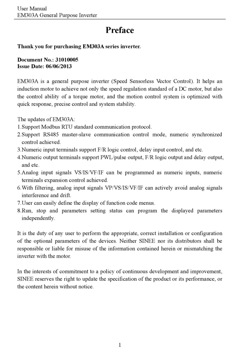
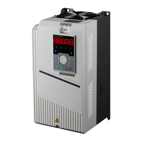
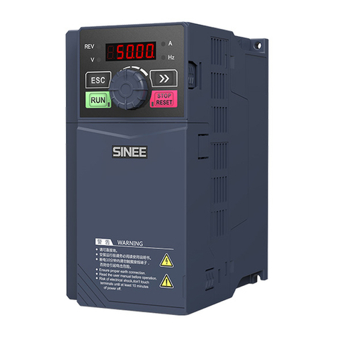
Sinee EM100-0R4-1B User manual

User Manual
EM100 Mini Inverter
1
Preface
Thank you for purchasing EM100 series mini inverter.
Document No.: 31010008
Version No.:103
Issue Date: 06/03/2013
EM100 mini inverter is a compact, intuitive, reliable and performing AC variable speed
drive for 3-phase induction motors.
This manual offers the general information of installation, wiring, function parameters,
daily maintenance, and fault diagnosis of EM100 mini inverter.
It is the duty of any user to perform the appropriate, correct installation or configuration
of the optional parameters of the devices. Neither SINEE nor its distributors shall be
responsible or liable for misuse of the information contained herein or mismatching the
inverter with the motor.
In the interests of commitment to a policy of continuous development and improvement,
SINEE reserves the right to update the specification of the product or its performance, or
the content herein without notice.
More updates and information are available at www.sinee.cn.

User Manual
EM100 Mini Inverter
2
CONTENTS
1. SAFETY INFORMATION ..........................................................................................3
1.1SAFETY PRECAUTIONS............................................................................................3
1.2 PRECUATIONS ...........................................................................................................6
2. OVERVIEW ..................................................................................................................7
2.1 VERIFYING PRODUCT ...............................................................................................7
2.2 MODEL NUMBERING SCHEME AND NAMEPLATE .....................................................7
2.3 MODEL NUMBER ......................................................................................................8
2.4 TECHNICAL SPECIFICATIONS ....................................................................................8
2.5 OUTLOOK ...............................................................................................................11
2.6 OVERALL AND INSTALLATION DIMENSIONS ..........................................................12
3. INSTALLATION ........................................................................................................14
3.1 MECHANICAL INSTALLATION .................................................................................14
3.2 WIRING ...................................................................................................................23
4. KEYPAD OPERATION.............................................................................................38
4.1 KEYPAD ..................................................................................................................38
4.2 FUNCTION CODE CHECK AND EDITING METHOD ...................................................39
5. PARAMETER TABLES ............................................................................................43
5.1 FORMAT OF PARAMETER TABLES...........................................................................43
5.2 PARAMETER TABLES ..............................................................................................43
6. PARAMETER DESCRIPTION ................................................................................59
7. TROUBLESHOOTING ...........................................................................................102
7.1 FAULT AND CORRECTIVE ACTION ........................................................................102
7.2 COMMON FAULT AND TROUBLESHOOTING ..........................................................104
8. EMC(ELECTROMAGNETIC COMPATIBILITY) ............................................107
9. MAINTENANCE AND INSPECTION ..................................................................110
9.1 MAINTENANCE AND INSPECTION..........................................................................110
9.2 OUTLINE OF WARRANTY ......................................................................................111
APPENDIX A: EM100 MODBUS COMMUNICATION PROTOCOL.................112
1. APPLICATION SCOPE...............................................................................................112
2. PHYSICAL INTERFACE.............................................................................................112
3. PROTOCOL FROMAT................................................................................................112
4. EXPLANATION OF COMMAND .................................................................................112
5. DESCRIPTION OF PROTOCOL FORMAT ....................................................................114
6. EXAMPLE ................................................................................................................117
APPENDIX B: ACCESSORIES..................................................................................119

User Manual
EM100 Mini Inv
e
D
l
a
p
C
p
t
h
o
1.1 Safety Preca
u
Before Installat
i
Dange
r
1.
Do not in
broken.
2.
Do not in
inverter.
Dange
r
1.
Be caref
u
2.
Do not u
s
3.
Do not to
Installation:
Dange
r
1.Installati
o
2.Do not u
n
Cautio
1.
Do not le
a
2.
Install the
3.
Consider
t
a cabinet.
e
rter
3
1. Safety I
n
D
anger: The addition of this
a
bel indicates that an electr
i
ersonal injury if the instructi
o
C
aution: This is the safety
otential personal injury haz
a
h
is symbol to avoid possible i
n
r other devices.
u
tions
i
on
r
stall the product if the packa
g
stall the product if the label o
r
u
l of carrying or transportatio
n
s
e damaged product or the in
v
uch the parts of control syste
m
r
o
n base shall be metal or othe
r
n
screw the fixing bolts, espec
i
n
a
ve cable strips or screws in t
h
product at the
p
lace with les
s
t
he installation space for cool
i
n
formation
symbol to a Danger or War
n
i
cal hazard exists, which w
i
o
ns are not followed.
alert symbol. It is used to
a
rds. Obey all safety messag
e
n
jury or
a risk of damage to
g
e is with water, or compone
n
n the package is not identical
n
. Risk of devices damage.
v
erte
r
s missing component. R
i
m
with bare hands. Risk of E
S
r
non-flammable material. Ri
s
i
ally the bolts with red mark.
h
e inverter. Risk of inverter d
a
s
vibration and no direct sunli
g
i
ng
p
urpose when the inverte
r
n
ing safety
i
ll result in
alert you to
e
s that follow
the products
n
t is missing or
to that on the
i
sk of injury.
S
D hazard.
s
k of fire.
a
mage.
g
ht.
r
is installed in

User Manual
EM100 Mini Inv
e
Wiring:
Dange
r
1.Wiring
m
2.Circuit-
br
3.Be sure
t
standard
w
4.Groundi
n
5.Dual key
p
Cautio
1.Never c
o
inverter.
P
inverter
d
2.Be sure t
h
should b
e
3.Do not c
o
4.Tighten t
e
5.Do not c
o
6.Do not
c
circuits.
O
7.Do not di
Before Power-o
n
Cautio
1.
Verify th
a
wiring o
f
inverter
a
Risk of i
n
2.
Never pe
r
Risk of a
c
Dange
r
1.
Inverter s
electrical
2.
Wiring o
f
accident.
e
rter
4
r
m
ust be performed by authoriz
e
r
eaker should be installed bet
w
t
hat the power supply is off
w
iring. Risk of electrical haz
a
n
g terminal must be grounded
.
p
ad is not recommended. Ris
k
n
o
nnect input power supply c
P
ay attention to the termina
l
d
amage.
h
at the wiring meets EMC re
q
e
in recommended sizes. Risk
o
nnect braking resistor to DC
e
rminals with screw drivers o
o
nnect phase-shifting capacit
o
c
onnect the solenoid switch
O
therwise, it will trigger over
c
sconnect internal wires of in
v
n
n
a
t the input voltage is identic
a
f
input terminals R, S, and T a
n
a
nd its peripheral circuits, and
n
verter damage.
r
form voltage withstanding te
c
cident.
r
hall be powe
r
-on only after t
h
hazard.
f
all peripherals should abide
b
e
d and qualified personnel. R
i
w
een inverter and the mains.
R
before wiring, and ground
i
a
rd.
.
Risk of electrical hazard an
d
k
of unexpected danger.
able to output terminals U,
l
symbols, connect them cor
r
q
uirements and local safety st
a
of accident.
bus terminal & . Risk o
f
f specified torque. Risk of fir
e
o
r and LC/RC noise filter to o
u
and electromagnetic conta
c
c
urrent protection, o
r
damage
v
erter. Risk of inverter damag
e
a
l to the rated voltage of prod
u
n
d o
u
t
p
ut terminals U, V, an
d
all wires should be in good c
st on inverter, it has been do
n
h
e front cover is assembled.
R
b
y the guide of this manual.
R
i
sk of danger.
R
isk of fire.
i
nverter as per
d
fire.
V, and W of
r
ectly. Risk of
a
ndard. Cables
f
fire.
e
.
u
tput circuits.
c
tor to output
inverter.
e
.
u
ct, correct
d
W, wiring of
onnection.
n
e at ex-works.
R
isk of
R
is
k
of

User Manual
EM100 Mini Inv
e
After Power-o
n
Dange
r
1.
Do not to
electrical
2.
Do not to
electrical
3.
After po
w
automati
c
or wiring
Dange
r
1.
If autotu
n
Risk of a
c
2.
Do not c
h
During Operati
o
Dange
r
1.
Do not to
burning.
2.
Non-
p
ro
fe
injury or
d
Cautio
1.
Prevent a
n
device d
a
2.
Do not c
o
damage.
Maintenance
Dange
r
1.
Maintain
2.
Maintain
b
etween
D
charge o
n
3.
Mainten
a
p
ersonal
i
4.
Paramete
r
should b
e
e
rter
5
n
r
uch the inverter and its perip
h
hazard.
uch any input/output termina
l
hazard.
w
er is on at the first time, inv
e
c
ally. Meanwhile, do not touc
h
terminal of moto
r
with bare
h
r
n
ing is required, be careful of
c
cident.
h
ange the defaults of paramet
e
o
n
r
uch cooling fans, heatsink or
fe
ssionals shall not detect sig
n
d
evice damage.
n
n
y foreign items from being l
a
mage.
o
ntrol start/stop of inverter by
r
and inspect devices after po
w
and inspect inverter only aft
e
D
C bus terminals & , an
d
n
capacitor may cause
p
erson
a
a
nce and inspection can only
b
i
njury.
r
setting is required if inverte
r
e
performed after powe
r
-off.
h
eral circuits with wet hands.
l
s of inverte
r
with bare hands
.
e
rter will detect external circu
i
h
wiring terminals U, V, and
W
h
ands. Rick of electrical haza
r
personal injury when motor i
s
e
rs. Risk of devices damage.
discharge resisto
r
with bare
h
n
als during operation. Risk of
eft in the devices during ope
r
ON/OFF of contactor. Risk
o
w
er is off. Risk of electric haz
a
e
r the voltage is lower than D
C
d
power is off for 5 minutes.
T
a
l injury.
b
e performed by professional
s
r
has been replaced. Plug-in
&
Rick of
.
Rick of
i
t
W
of inverter,
r
d.
s
running.
h
ands. Risk of
personal
r
ation. Risk of
o
f device
a
rd.
C
36V
T
he residual
s
. Risk of
&
plug-out

User Manual
EM100 Mini Inverter
6
1.2 Precautions
Motor Insulation Inspection
When the motor is used for the first time or when the motor is reused after being kept, or
when periodical inspection is performed, insulation inspection shall be conducted with
motor so as to avoid damaging the inverter because of the insulation failure of the motor
windings. The motor wires must be disconnected from the inverter during the insulation
inspection. It is recommended to use the 500V megameter, and the insulating resistance
measured shall be 5Mat least.
Motor Thermal Protection
If the motor rating does not match that of the inverter, especially when the rated power
of the inverter is higher than that of the motor, adjust motor protection parameters in the
inverter or install thermal relay to protect motor.
Operating with the Frequency Higher than Grid Power Frequency
Output frequency of EM100 is 0.00Hz ~ 320.00Hz. If EM100 is required to operate
above 50.00Hz, please take the endurance of mechanical devices into consideration.
Mechanical Vibrations
Inverter may encounter mechanical resonance point of the load device at certain output
frequencies which can be avoided by setting the skip frequency parameters of the
inverter.
Motor Heat and Noise
Since output voltage of inverter is PWM wave and contains a certain amount of
harmonics, so that the temperature, noise and vibration of the motor will be higher than
those when the inverter runs at grid power frequency.
Piezosistor or the Capacitor Improving Power Factor on Output Side
The inverter outputs PWM wave, do not install capacitor to improve power factor or
piezosistor for lightning protection on output side. Otherwise, it will trigger inverter
instantaneous overcurrent or even damage inverter.
Applied with the Rated Voltage
Apply EM100 with the rated voltage. Failure to comply will damage inverter. If required,
take a transformer to boost or step-down voltage.
Do Not Apply a 3-Phase Input Inverter to 2-Phase Input Applications
Do not apply a 3-phase input EM100 inverter to 2-phase input applications. Otherwise, it
will result in faults or damage inverter.
Lightning Protection
EM100 has integrated lightning over-current protection device which has certain
self-protection capacity against the lightning. Additional protection devices have to be
installed between inverter and power supply in the area where lightning occurs
frequently.
Altitude Derating
In altitudes above 1000m above sea level, the derating is required because of poor
cooling effect due to rare air. Contact SINEE for technical support.
Cautions for Inverter Disposal
The electrolytic capacitors on the main circuit and PCBA may explode when they are
burnt. Emission of toxic gas may be generated when the plastic parts are burnt. Please
dispose inverter as industrial wastes.

User Manual
EM100 Mini Inv
e
2.1 Verifying Pr
o
zNever install
of injury.
Refer to the follo
w
If the products
a
purchase order.
Any part dama
g
Any screw loo
s
2.2 Model Num
b
Model N
u
Product Categ
o
EM: Inverter
Product Series
:
100: Mini Inve
r
Power Ratings
0R4
0.4kW
Namepla
t
e
rter
7
2. Ove
o
duct
C
an inverter that is damaged o
w
ing table, and check and ve
r
Item
a
re identical to the C
h
la
b
g
ed. C
h
s
ened. C
h
b
ering Scheme and Namepl
a
u
mbering Scheme
o
r
y
:
r
te
r
……
……
2R2
2.2kW
……
……
EM 100 –0R
7
t
e
Model No. : E
M
Rated Power : 0.
7
Input Voltage: A
C
Rated Current: 4.
8
Serial No.:
Shenzhe
n
rview
C
aution
r missing components. Other
w
r
ify the product.
Action
h
eck the devices reference ma
r
b
el.
h
eck the outlook if any dama
g
h
eck with a screwdriver if nec
a
te
7
–1 B
B: Integrated Brakin
g
None: No Brakin
g
Voltage Class:
1: 1-phase 220
V
3: 3-phase 380
V
M
100-0R7-1B
75
kW
C
220V
8
A
n
Sine Electric Co., Ltd.
w
ise, a risk
r
ked on the
g
es.
essary.
g
Uni
t
g
Unit
V
V
/415V

User Manual
EM100 Mini Inverter
8
2.3 Model Number List
Table 2-1 EM100 Model Number List
Rated Input
Voltage Model No. Motor
Power(kW)
Rated Output
Current(A)
1-phase AC220V
EM100-0R4-1B 0.4 2.8
EM100-0R7-1B 0.75 4.8
EM100-1R5-1B 1.5 8.0
EM100-2R2-1B 2.2 10.0
3-phase
AC380V/415V
EM100-0R7-3B 0.75 2.8
EM100-1R5-3B 1.5 4.8
EM100-2R2-3B 2.2 6.2
EM100-4R0-3B 4.0 9.2
EM100-5R5-3B 5.5 13
EM100-7R5-3B 7.5 17
EM100-011-3B 11 25
EM100-015-3B 15 32
2.4 Technical Specifications
Table 2-2 EM100 Technical Specifications
Items Specifications
Input
EM100-XXX-1B: 1-phase 220V (±20%)
50~60Hz (±5%)
EM100-XXX-3B:3-phase 380V/415V
(±20%), 50~60Hz (±5%)
Output
Max. Output Voltage 3-phase, from 0 to Usupply.
Rated Output Current 100% rated current non-stop output
Max. Overload Current
150% rated current for 1 minute, 180% rated
current for 10 seconds, 200% rated current
for 2 seconds
Basic
Control
Function
Control Mode V/F, SVC
Speed Setting Mode
Speed setting mode, analog setting, RS485
Communication setting, terminal numeric
setting, keypad setting.
Running Mode Keypad, control terminals (2-wire sequence,
3-wire sequence), RS485
Frequency Control
Range 0.00~320.00Hz
Input Frequency
Resolution
Numeric input:0.01Hz
Analog input: 0.10 Hz

User Manual
EM100 Mini Inverter
9
Governor Deflection 1:50
Speed Control
Accuracy 1.0%
Acceleration/
Deceleration Time 0.01~600.00 seconds
V/F Features Rated output voltage: 5%~100% adjustable
Frequency base:20.00~320.00Hz adjustable
Torque Boost Automatic torque boost, fixed torque boost
curve, customer defined V/F curve scaling
Start Torque 150%/1Hz
AVR
AVR is active while output voltage remains
unchanged if input voltage is varying.
Accuracy: ±10V at rated input voltage
Automatic Current
Limit
Automatically limit output current, avoid
frequent overcurrent trip
DC Brake Brake time:0~30S
Brake current: 150% rated current
Signal Input Source
Numeric, analog voltage, analog current,
preset speed, simple PLC, Modbus
communication, wobbbulation frequency,
and PID. Primary frequency setting and
auxiliary frequency setting integrated and
terminal switch.
Input/
Output
Function
Auxiliary Power
Supply 10V/10mA , 24V/50mA
Numeric Input
Terminal
Internal electrical impedance: 27k
Acceptable external input:0~20V, the
terminal is on at low level.
Maximum input frequency: 1kHz
6 numeric programmable input terminals,
user can define terminal functions via
function code.
Analog Input
Terminals
1 voltage input:0~10V, and another input
can be configurated as a current input: 4~

User Manual
EM100 Mini Inverter
10
20mA or a voltage input:0~10V
Input impedance:
voltage input: 1M, current input: 250
Accuracy: 0.2%
Numeric Output
Terminal
1 programmable OC output
Max. load capacity: 50mA/24V
Output frequency range:0~1kHz
1 programmable relay output, EA-NO,
EB-NC, EC-Common port
Contact capacity: 3A/AC250V
Power factor:>0.4 or 1A/DC30V
Analog Output
Terminal
1 programmable analog output terminal,
output: 0~10V
Max. load capacity: 2mA
Accuracy: 0.1V
Display LED 5-bit display, 8 input keys
Protection Protections
Overcurrent, overvoltage, input/output phase
loss, output short-circuit, overheating, and
etc.
Application
Conditions
Installation Site
Indoor, with altitude less than1,000 meters,
free from dust and corrosive gas, and direct
sunlight
Ambient Temperature
-10℃~+40℃. In the temperature range +40
°C…+50 °C, the rated output current is
decreased by 1% for every additional 1 °C.
20%~90%RH (no condensation)
Vibration ﹤0.5g
Storage Temperature -20°C~+65°C
Installation Method Wall mounting
Protection Grade IP20
Cooling Method Forced air cooling
Noise 38-62dB/A(See 3.1.4.3 for detail.)
Safety Standard IEC61800-5-1:2007
EMC Standard IEC61800-3: 2004

User Manual
EM100 Mini Inv
e
2.5 EM100 Outl
o
Housin
g
Keyp
a
Term
i
Cove
r
Contr
o
e
rter
11
o
ok
g
Uppe
r
a
d
i
nal
r
o
l Terminal Power
Terminal
DIN Rail Release
B
EM10
0
Main Air In
l
Namepl
a
Air Outl
e
Housi
n
B
a
Main Air Ou
t
B
utton
0
ID
l
e
t
a
te
e
ts
n
g
a
se
t
le
t

User Manual
EM100 Mini Inverter
12
2.6 Overall and Installation Dimensions
2.6.1 Overall Dimensions
Model
No.
Unit
(mm)
EM100-0R4-1B
EM100-0R7-1B
EM100-1R5-1B
EM100-2R2-1B
EM100-0R7-3B
EM100-1R5-3B
EM100-2R2-3B
EM100-4R0-3B
EM100-5R5-3B
EM100-7R5-3B
EM100-011-3B
EM100-015-3B
W 95 110 130 150
W1 85 100 118 138
W2 11 11 / /
H 152 163 220 289.5
H1 142 153 209 272
H2 159 170 / /
H3 130.5 140.5 / /
H4 110.5 121.5 / /
D 117 132 152.5 173
D1 130 145 165.2 185.7
D2 74 84 104.7 125
d1 4.5 4.5 5.5 5.5
d2 4.5 5 / /
N.W./Kg 1 1.5 2.8 5.0
Frame SIZE1 SIZE2 SIZE3 SIZE4
Remarks:
D2:The distance between the entrance hole of power cable and the installation plate.
Symbol / indicates that the size is not available.
2.6.2 Diagram of Overall and Installation Dimensions

User Manual
EM100 Mini Inverter
13
2.6.3 Keypad Dimensions
2.6.4 Dimensions of Keypad Chassis (Accessories) and Mounting Holes
Remarks: Please contact distributors or SINEE for keypad chassis if needed.

User Manual
EM100 Mini Inv
e
3.1 Mechanical
I
3.1.1 Installatio
n
Caution
1. Always h
o
Risk of i
n
2. Installati
o
Risk of fi
r
3. Install a
temperat
u
Overheati
n
3.1 .2 Installatio
n
Consideratio
n
zGood ventil
a
zAmbient te
m
zNo high te
m
other liquid
d
zNever instal
l
zNo direct su
n
zNo flammab
zNo dust, flo
a
zFirm and ste
3.1.3 Precaution
Take protective
p
articles or dust
objects after inst
a
3.1.4 Installatio
n
A fan is integrat
e
for the purpose
o
EM100 and its
pe
and vertically. S
e
and mass airflow
e
rter
14
3. Inst
a
I
nstallation
n
Recommendations
o
ld the case when carrying
t
n
jury if only holding the termi
o
n base shall be metal or ot
h
r
e if installing the inverter on
cooling fan when instal
l
u
re shall be lower than 40℃
n
g may result in fire or other
a
n
Site
n
s for installation site:
a
tion indoo
r
m
perature: -10°C~+40°C, 20
%
m
perature and high moisture,
h
d
rops
l
on flammable materials
n
light
le, corrosive gas or liqui
d
a
ting fiber or metal particles
ady installation base
s
measures during installatio
n
from entering the inverter w
h
a
llation.
n
Direction, Space and Cool
i
e
d in EM100 for forced air co
o
f good cooling circulation.
e
ripheral objects. Multi-EM1
e
e followings for specific sp
a
.
a
llation
t
he inverter.
nal cover.
h
er non-flammable material
inflammable materials.
l
ing inverter in a cabin
e
at air inlet.
a
ccidents.
%
~90%RH(No condensatio
n
h
umidity:<90%RH, no wate
r
n
to prevent foreign matte
r
h
en drilling. Please take off
t
i
ng
oling. EM100 has to be insta
l
Sufficient spaces have to be
00 can be installed in parall
e
a
ce requirement, heat dissip
a
.
e
t, and air
n
)
r
drops or any
r
s like metal
t
he protective
l
led vertically
left between
e
l horizontally
a
ting capacity

User Manual
EM100 Mini Inverter
15
3.1.4.1 Installation Space of Single EM100
3.1.4.2 Vertical Installation of Multi-EM100

User Manual
EM100 Mini Inverter
16
3.1.4.3 Table of Heat Dissipating Capacity (HDC), Mass Airflow(MAF) and Noise
of Single EM100
Model No. Frame MAF
(CFM)
MAF
(m3/h)
HDC
(W)
Noise
(dB/A)
EM100-0R4-1B SIZE1 8 13.6 42 38
EM100-0R7-1B 8 13.6 70 38
EM100-1R5-1B
SIZE2
13 22 90 40
EM100-2R2-1B 13 22 120 40
EM100-0R7-3B 13 22 75 40
EM100-1R5-3B 13 22 85 40
EM100-2R2-3B 13 22 105 40
EM100-4R0-3B 13 22 150 40
EM100-5R5-3B
SIZE3
31.2 53 174 45
EM100-7R5-3B 31.2 53 252 45
EM100-011-3B 31.2 53 362 45
EM100-015-3B SIZE4 106 180 520 55
Remarks:
1. The values listed in the table refer to that the HDC and the MAF required when single
EM100 is mounted in an enclosed space.
2. The HDC is calculated based on the rated voltage, rated current and preset carrier
frequency of each model.
3. If multi-EM100 has to be installed in an enclosed space, please add HDC and MAF.
3.1.4.4 Load Shedding Curve

User Manual
EM100 Mini Inverter
17
3.1.5 Installing with Screws
a. 4-hole Installation
See Overall and Installation Dimensions for the dimensions of 4-hole (Hole a). Refer to
Figure a, and punch 4 holes on the installation panel. Put the inverter against the panel
and mate 4 holes, and then tighten screws in the 4 holes (Tighten any of the 2 screws in
diagonal position, tighten 4 holes with screws for strengthened installation. Screw size:
M4xL, L>12mm, tightening torque: 1N.m±10%)
Figurea Figureb
Do not take the sunk screws as shown in the
picture. Otherwise, inverter may be damaged.
Take screws combined with springs and plain
gaskets to install inverter.

User Manual
EM100 Mini Inverter
18
b. 3-hole Installation
See Overall and Installation Dimensions for the dimensions of 3-hole (Hole b). Refer to
Figure b, and punch 3 holes on the installation panel with screws in each of them. Do not
tighten the screws, leave a distance of 7.5~9mm between the gaskets and installation
panel, hung the inverter onto the 3 screws from top to bottom (Screw size: M4xL,
L>16mm, tightening torque: 1N.m±10%), and then tighten the 2 screws at the bottom.
3.1.6 DIN Rail Installation (DIN Rail Width: 35mm)
See Overall and Installation Dimensions for the dimensions of DIN rail. Refer to the
following Figure, install and remove the inverter by pushing the DIN rail release button.
DIN
Rail
Mount multi-inverter in parallel with DIN rail:
3.1.7 Flange Mounting (For the Models with Frame SIZE3&4 )
Unit
(mm)
Frame
W L W1 W2 W3 L1 L2 L3 d H1 H2
SIZE3 138 223 170 157 37 261 249 99 5.5 84 81
SIZE4 156 290 190 177 37 329 317 142 5.5 131 70
Remarks Size of
mounting hole
Size of depth

User Manual
EM100 Mini Inverter
19
Remarks:
Instruction of assembling the flange: Assemble the flange left and right on the left and
right sides of EM100 first, fasten the screws on the top and at the buttom, locate the
inverter with flange into the mounting hole, and tighten the screws to finish the
assembly.

User Manual
EM100 Mini Inverter
20
3.1.8 Disassembly and Assembly of Keypad
a. Disassemble keypad. See following Figure: Push the buckle on the keypad in
Direction 1 first, and then lift up the keypad in Direction 2.
b. Assemble keypad. See following Figure: Place keypad in the slot in Direction 1, and
then press the keypad in Direction 2 until it clicks into right place.
This manual suits for next models
11
Table of contents
Other Sinee Inverter manuals
Popular Inverter manuals by other brands
Tripp Lite
Tripp Lite PowerVerter RV1250ULHW Specifications

Centech
Centech 64867 owner's manual

Tripp Lite
Tripp Lite APSWX Series owner's manual

DualLite
DualLite LG125S Installation instructions and user manual
Delta
Delta PPM CT16 101 Quick Installation Guideline
APsystems
APsystems QS1 Installation and user manual
