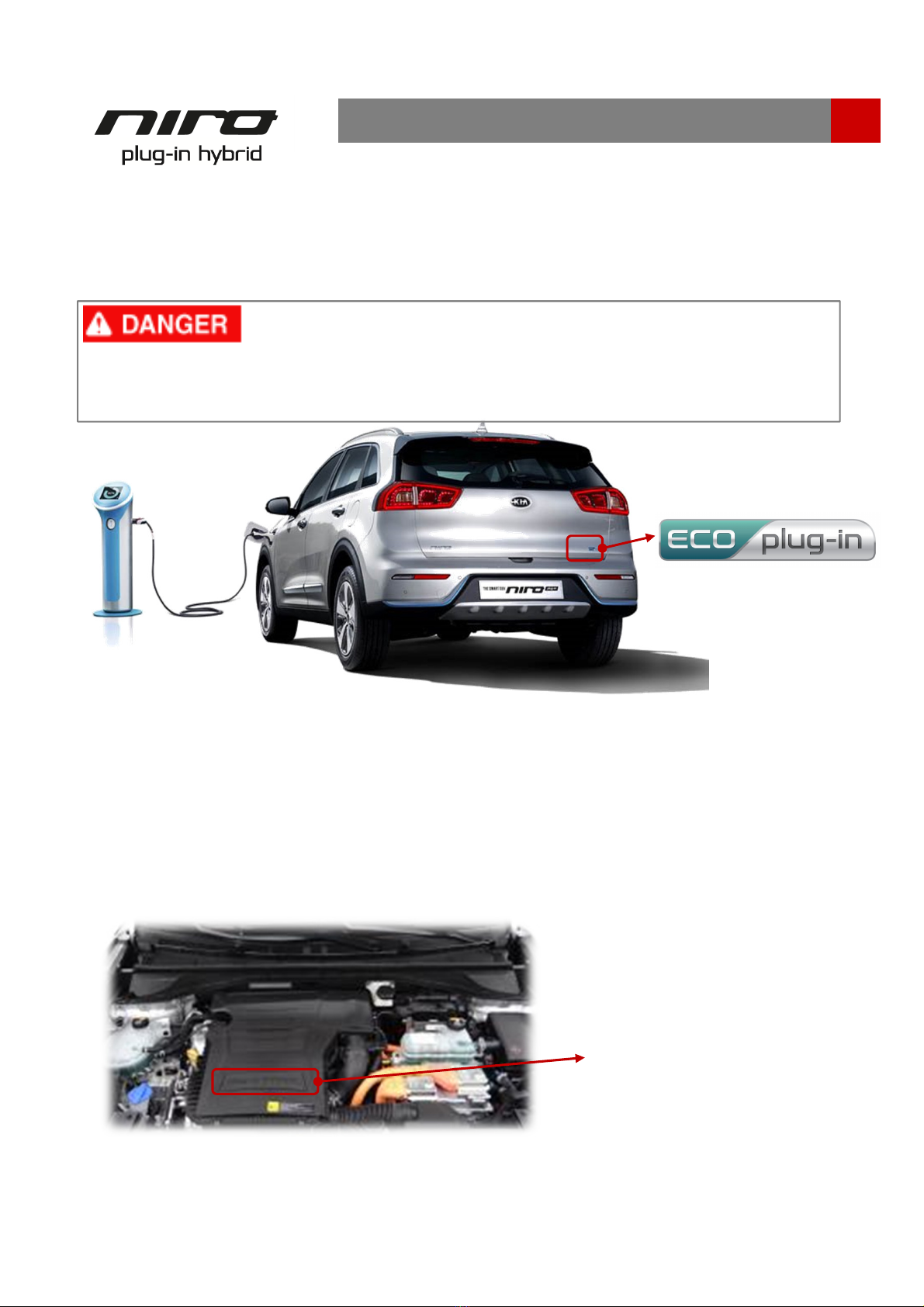
Kia NIRO User manual

Emergency Rescue Guide Manual

Introduction
Niro Identification
General Vehicle Description . . . . . . . . . . . . . . . . . . . . . . . . . . . . . . . . . . . . . . . . . . . . . . . . . . .
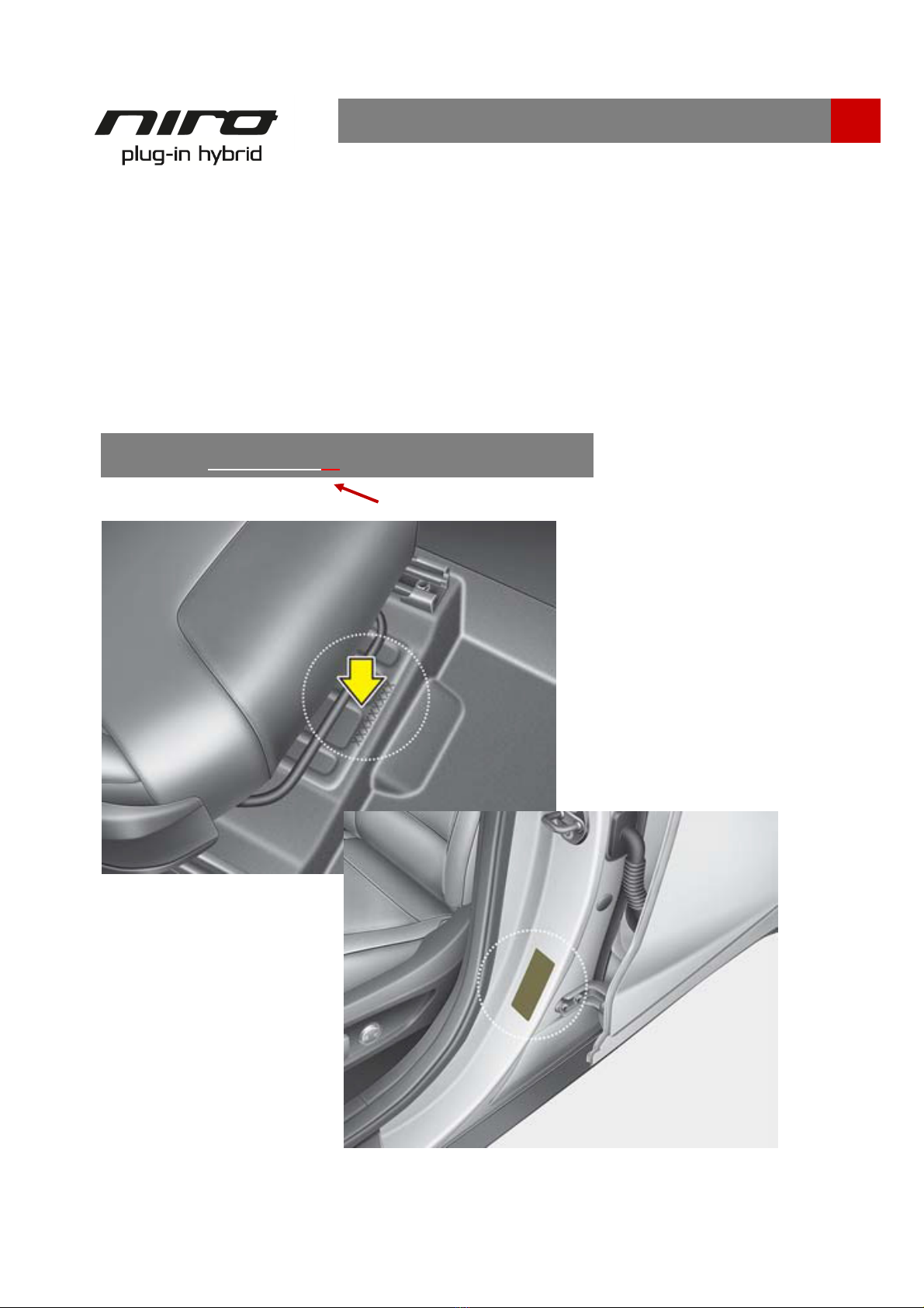
Identifying a Kia Niro . . . . . . . . . . . . . . . . . . . . . . . . . . . . . . . . . . . . . . . . . . . . . . . . . . . . . .
Niro Main Electronic Systems
Power Electronics Specification . .. . . . . . . . . . . . . . . . . . . . . . . . . . . . . . . . . . . . . . . . . . . . . . .
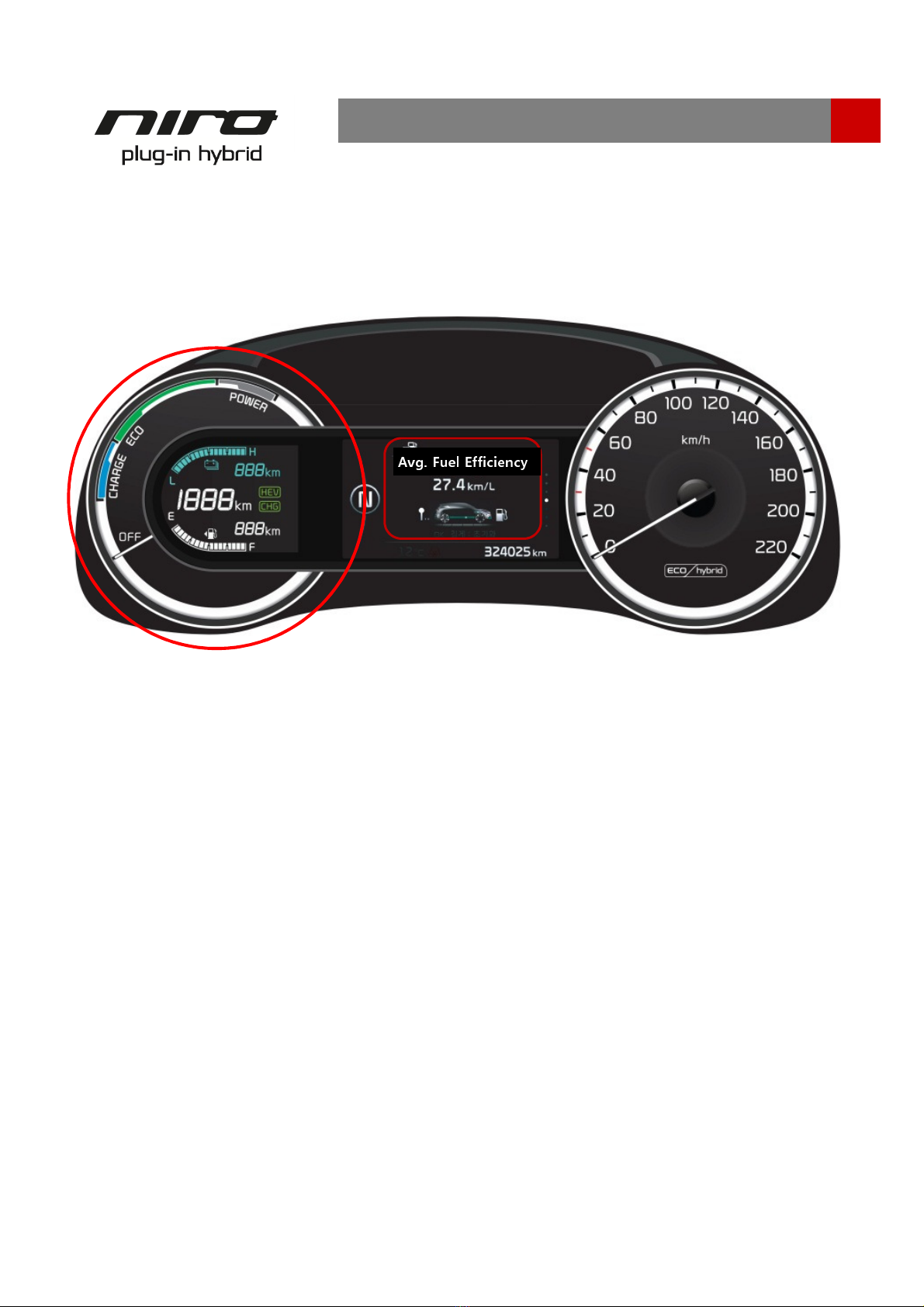
Vehicle Components . . . . . . . . . . . . . . . . . . . . . . . . . . . . . . . . . . . . . . . . . . . . . . . . . . . . . .
Air ag system (SRS: Supplemental Restraint System). . . . . . . . . . . . . . . . . . . . . . . . . . . . . . . . .
Emergency Procedures
Initial Response: Identify, Immo ilize and Disa le. . . . . . . . . . . .. . . . . . . . .. . . . . . . . . . . . . . . .
Extraction Operations. . . . . . . . . . . . . . . . . . . . . . . . . . . . . . . . . . . . . . . . . . . . . . . . . . . . . . . .
Vehicle Fire .. . . . . . . . . . . . . . . . . . . . . . . . . . . . . . . . . . . . . . . . . . . . . . . . . . . . . . . . . . . . . .
Su merged or Partially Su merged Vehicles. . . . . . . . . . . . . . . . . . . . . . . . . . . . . . . . . . . . . . . .
High Voltage Battery Damage and Fluid Leaks . . . . . . . . . . . . . . . . . . . . . . . . . . . . . . . . . . . . . .
Roadside Assistance
Towing
. . . . . . . . . . . . . . . . . . . . . . . . . . . . .. . . . . . . . . .. . . . . . . . . . . . . . . . . . . . . . . . . . . .
Emergency Starting. . . . . . . . . . . . . . . . . . .. . . . . .. . . . . . . . . . . . . . . . . . . . . . . . . . . . . . . .
1
3
3
6
18
12
20
24
23
23
Contents
22
20
12
10
7
6
3
Document Purpose. . . . . . . . . . . . . . . . . . . . . . . . . . . . . . . . . . . . . . . . . . . . . . . . . . . . . . . . .
Vehicle Description. . . . . . . . . . . . . . . . . . . . . . . . . . . . . . . . . . . . . . . . . . . . . . . . . . . . . . . . .
1
2
NO
-CUT ZONES. . . . . . . . . . . . . . . . . . . . . . . . . . . . . . . . . . . . . . . . . . . . . . . . . . . . . . . .
19

Document Purpose
The purpose of this document is to familiarize first responders and the towing/roadside
assistance industry with the proper methods to handle the Niro PHEV in an emergency
situation. This guide gives a asic overview of key vehicle systems and instructions for
dealing with the different types of emergencies encountered y first responders. The
emergency response procedures for this vehicle will provide how to deal with the high
voltage electrical system.
1
Introduction
Within this Emergency Response Guide you will find
Notices
,
Cautions
,
Warnings
and
Dangers
which provide critical information and help you do your jo safely and
efficiently. Below are the definitions of these terms. When you see a
Notice
,
Caution
,
Warning
or
Danger
, e certain you understand the message efore you attempt to
perform any part of an emergency response procedure.
A Notice alerts you to a situation which, if not avoided, could result in vehicle damage.
A Caution alerts you to a hazardous situation which, if not avoided, could result in minor or
moderate injury.
A Warning alerts you to a hazardous situation which, if not avoided, could result in death
or serious injury.
A Danger alerts you to a hazardous situation which, if not avoided will
result in death or serious injury.

2
Introduction
Vehicle Description
As with other PHEVs and HEVs, the Kia Niro PHEV uses the com ination of a conventional
gasoline powered internal com ustion engine and a high voltage electric motor to propel
the vehicle. This com ination provides for improved gas mileage over a conventional Kia
with a standard 4-cylinder engine.
Unlike HEVs, Niro PHEV’s high voltage attery can e recharged through the charge port
on the left fender. It increases the driving range in EV mode and also fuel efficiency. The
high voltage attery is recharged automatically while driving. This is accomplished through
the engine and regenerative raking system that produces electricity while driving and
raking.

A “plug-in Hy rid” adge is also displayed under the hood on the engine cover. Also, the
High Voltage ca ling is orange per SAE standard.
Ca les run from the ottom of the vehicle
where they connect the High Voltage Battery to the HPCU (Hy rid Power Control Unit),
Motor, Inverter, and other High Voltage components at the front of the vehicle.
The presence of orange ca les under the hood identifies the vehicle as an PHEV
.
3
Niro Identification
Engine
Room
Plug-in ybrid
Identifying a Kia
Niro
The
Niro PHEV can e easily identified y the “Eco plug-in” logo attached on the tail gate.
“Eco
plug-in” logo on tail gate
The hy rid logo can ecome hidden after a crash due to damage to the vehicle. Always e
sure to utilize additional methods of identification efore determining the vehicle is not a
hy rid.
Electrocution Risk

The VIN (Vehicle Identification Num er) identifies
the Hy rid with a “D” displayed in the
8th position, as shown in the elow drawing.
The VIN can e found:
1) Underneath the front passenger seat (or driver seat).
2) On the vehicle certification la el attached to the driver’s side (or passenger) center pillar.
4
Niro Identification
VIN Label
XXXXXXXDXXXXXXXXX
8th position

The
Niro PHEV Cluster Instrument Panel displays the PHEV specific features such as high
voltage attery SOC (State of Charge) in the highlighted part.
5
Niro
Cluster Instrument Panel
Niro Identification
Avg. Fuel Efficiency

6
Niro Main Electronic Systems
igh Voltage
System
High-voltage attery
Hy rid
Starter
Generator (HSG)
Motor
Transmission
Motor
Type Permanent magnet synchronous motor
Max. Output P(kW) 60.5 (44.5)
Max Torque l -ft(Nm) 125 (170)
PCU
Inverter Input Voltage(V) 240 ~ 413
LDC Max. Output (kW) 1.8
igh Voltage
Battery
Type Lithium-ion polymer
Rated Voltage (V) 360
Capacity (Ah) /
Energy (kWh) 24.7 / 8.9
Quantity for Pack
(Cell / Module) 96Cells / 24Modules
12V attery

7
Niro Main Electronic Systems
Vehicle
components
12V
auxiliary battery
The 12V auxiliary attery is located in the right side of the luggage room, and powers all of
the vehicle’s standard electronics like radio, air conditioner, etc. Also, it powers the HPCU
(Hy rid Power Control Unit) which controls high voltage current to main electronic systems
like the motor.
12V Auxiliary Battery

8
Niro Main Electronic Systems
Motor
The motor of the PHEV converts electrical energy into
motive force with a Max. power of 60.5Hp (44.5kW)
and Max. torque of 125l
-ft (170Nm).
ybrid Power Control Unit ( PCU)
The HPCU includes an Inverter and LDC (Low Power
DC
-DC Converter) in one housing. The inverter
converts DC to AC to supply electricity to the motor.
It also converts AC to DC to charge the high voltage
attery. The LDC transfers high voltage electricity to 12
voltage to charge 12V auxiliary attery.
Integrated Battery System ( igh
voltage and Low voltage)
Low voltage attery is
separate in DE PHEV.
High voltage modules
supply and store electric energy to traction
motor
and it is a Lithium ion polymer attery with specifications,
360V / 24.7Ah / 8.9kWh.
It is located in the under the rear seat of the
Niro.
ybrid Starter Generator ( SG)
The
HSG restarts the engine at HEV mode and also
charges the high voltage attery while driving.

9
Niro Main Electronic Systems
igh Voltage Orange Cabling
The High Voltage ca ling is orange,
per SAE standard. Ca les run under the floor of the
vehicle and connect the High Voltage Battery to the HPCU, Motor, LDC, Inverter, OBC and
other High Voltage components in front of the vehicle.
The presence of orange ca les under the hood, on
the under-floor attery compartment,
or orange shielding under the car, identifies the vehicle as an electric vehicle.
Never cut or disconnect the high voltage orange ca ling and connectors without first
disa ling the system y removing the safety plug.
Exposed ca les or wires may e visi le inside or outside the vehicle. Never touch
the wires, ca les, connecters, or any electric components efore disa ling the
system, to prevent injury or death due to electrical shock.
Failure to follow these instructions can lead to death y electrical shock.
igh Voltage Cables
The
OBC is the attery charging equipment that
converts external AC to DC to charge the high voltage
attery.
On
-Board Charger (OBC)

10
Niro Main Electronic Systems
Airbag
system (SRS: Supplemental Restraint System)
Air
bag
Seven air ags are installed in the Niro, located in standard areas of the vehicle.
Before emergency procedure, make sure the vehicle ignition switch is turned off,
disconnect the negative connector from the 12V auxiliary attery (located on passenger
side, cargo area) to prevent accidental deployment of undeployed air ags.
Seat Belt Pretensioner
The
Niro is equipped with driver’s and front passenger’s seat elts with pretensioners.
When the seat elt pretensioners are activated in a collision, a loud noise may e heard
and fine dust, which may appear to e smoke, may e visi le in the passenger
compartment. These are normal operating conditions and are not hazardous. The seat elt
pretensioner assem ly mechanisms may ecome hot during activation, and may need
several minutes to cool after they have een activated.
❈The actual air ags and seats in the vehicle may differ from the illustration.
(1) Driver front air ag
(2) Passenger front air ag
(3) Side air ag
(4) Curtain air ag
(5) Driver’s knee air ag

11
Niro Main Electronic Systems
Airbag system
components
To avoid injuries caused
y accidental deployment of undeployed air ags
Do not cut the red colored part on the a ove layout.
Make sure the vehicle ignition switch is turned off, disconnect the negative ca le
from the 12V auxiliary attery (located ehind the rear passenger seat-drivers
side), and wait 3 minutes or longer to allow the system to deactivate.
Failure to follow any of these instructions may result in serious injury or death from
accidental deployment of the air ag system.
Undeployed
Airbags
1.
Driver Air ag (DAB)
2. Clock Spring
3.
Steering Wheel
4.
Seat Belt Pretensioner (BPT)
5. Passenger
Air ag (PAB)
6.
Side Air ag (SAB)
7. Curtain Air ag
(CAB)
8.
Front Impact Sensor (FIS)
9. Knee Air ag (KAB)
10. Pressure
Side Impact Sensor (PSIS)
11. Rear Side Impact Sensor (RSIS)
12.
Supplemental Restraint System Control
Module(SRSCM)
13
. Emergency Fastening Device (EFD)
14. Occupant Classification System (OCS)

12
Emergency Procedures
Initial Response: Identify, Immobilize and Disable
Identify
The
Niro is an Eco-electric vehicle. Emergency responders should respond to emergency
scenarios involving the Niro
accordingly eing careful to avoid contact with the high voltage
system within the vehicle.
The following procedures should e used whenever you are dealing with a
Niro at an
emergency scene. All other operations should e consistent with your department’s
standard operating procedures or guides. When a Hy rid is damaged in a crash, the high
voltage safety systems may have compromised and present a potential high voltage
electrical shock hazard. Exercise caution and wear appropriate personal protective
equipment (PPE) safety gear, including high voltage safety gloves and oots. Remove all
metallic jewelry, including watches and rings.

13
Emergency Procedures
Immobilize
The next step is to immo ilize the vehicle to prevent any accidental movement that can
endanger response personnel and civilians alike.
When in "READY" mode the lamp is illuminated on the Instrument Panel, the
vehicle can move almost silently using the electric motor. Responders should approach the
vehicle from the sides and stay away from the front or rear as they are potential paths of
travel. Immo ilizing the vehicle in the following procedure.
Chock the wheels Set the parking rake.
Position the shift
lever in park (P)

14
Emergency Procedures
Disable
After the vehicle is secured to prevent movement, the final step in the initial response
process is to disa le the vehicle, its SRS components and the high voltage electrical system.
To prevent current flow through the system, use one of the following procedures to disa le
the vehicle.
I . Disabling the System – Smart Key System and “POWER” START/STOP Button
1. Confirm the status of the READY light on
the instrument panel. If the READY
light is illuminated, the vehicle is on.
a) If the READY light is NOT
illuminated, the vehicle is off. Do not
push the “POWER” START/STOP
utton ecause the vehicle may start.
) To turn off the system, put the shift lever in the P (Park) position and press the
POWER utton.
Without depressing the brake pedal
Pressing
POWER button
POWER button
LED color Vehicle condition
Off Off
One time Am er Electrical accessories are
operational.
Two times Reddish orange The warning lights can e checked
efore the vehicle is started.
Three times Off Off
While depressing the brake pedal while a shift lever is in the P (Park) position
Pressing
POWER button
POWER button
LED color Vehicle condition
Off Off
One time Off Ready to drive
“POWER” START/STOP Button

15
Emergency Procedures
2. If necessary, lower the windows, unlock the doors and open the tail gate as required,
efore disconnecting the 12V attery. Once the 12V attery is disconnected, power
controls will not operate.
3. Before disconnecting 12V attery, move the Smart Key at least 6 feet (2 meters)
away from the vehicle to prevent accidental restart.
4. Use the following procedure to remove the safety plug
and disa le the high voltage attery:
c) Remove the luggage oard (A).
e) Lift up the hook (A) to the
direction of arrow.
d) After removing the olts,
remove the safety plug cover (A).
f) Unfasten the lever (A) to the
direction of arrow.
a) Remove the 12V attery cover (A). ) Disconnect the 12V attery (-) terminal.

16
Emergency Procedures
1. Open the hood.
II. Disabling the System – IG (Ignition) Fuse Removal
2. Remove the engine room fuse ox
cover.
3. If necessary, lower the windows,
unlock the doors and open the tail gate
as required, efore disconnecting the
12V attery (located in cargo area on
passenger side). Once the 12V attery
is disconnected, power controls will not
operate.
4. In the event the vehicle may not
e disa led using the “Power”
START/STOP Button, pull the IG1,
IG2 Fuse from the engine room fuse
ox. If the IG Relay cannot e
located, pull out all the fuses and
relays in the fuse ox.
Engine room fuse box

17
Emergency Procedures
If previously mentioned methods of disa ling system are unsuccessful, the vehicle is not
secured from accidental deployment of undeployed air ags and electric shock of high-
voltage components.
5. Remove the safety plug and disa le the high voltage attery
(Refer to No.4 procedure in page 15)
Before engaging in emergency response procedures, ensure the vehicle is disa led
and wait 5 minutes to allow the capacitor in the high voltage system to discharge
to avoid electrocution.
Exposed ca les or wires may e visi le inside or outside the vehicle. Never touch
the wires or ca les efore disa ling the system, to prevent injury or death due to
electrical shock.
Failure to follow these instructions can lead to death y electrocution.
Electrocution Risk

18
Emergency Procedures
Extraction Operations
Vehicle Stabilization
Use standard sta ilization (lifting) points, as
shown eside. Always e sure to connect to
a structural mem er of the vehicle and
avoid placing jacks and lifting devices under
high voltage ca les, fuel lines and other
areas not normally considered accepta le.
The
Niro is an Eco-electric model (HEV/PHEV). Because of the high voltage components
contained therein, first responders should pay special attention when they extract occupants
in the car. Before extraction operations, the first responders should "Identify, Immo ilize and
Disa le" the vehicle as discussed in sections on page 12-17.
Extraction
tools and procedure
When responding to an incident involving a Niro, we recommend that the first responders
follow their organization’s standard operating procedures for assessing and dealing with
vehicle emergencies.
When the first responders cut the vehicle, they should always pay special attention to the
air ag system, orange colored high voltage ca les and other high voltage components so that
the parts are not damaged, causing risks of explosion.
Location
of ultra-high strength steel
In the image, high strength steel is
used in the areas colored in lue and
ultra
-high strength steel is used in the
red colored areas. Depending on the
tools used, ultra high strength steel
can e challenging or impossi le to
cut.
Mild steel
High
strength steel
Ultra
-high strength steel
Other manuals for NIRO
3
This manual suits for next models
1
Table of contents
Other Kia Automobile manuals

Kia
Kia Sedona User manual

Kia
Kia RIO 2020 Assembly instructions

Kia
Kia MOHAVE 2014 User manual

Kia
Kia 2012 soul Specification sheet

Kia
Kia Forte 2014 User manual

Kia
Kia Fleet User manual

Kia
Kia 2000 Sportage User manual

Kia
Kia K5 2021 Parts list manual

Kia
Kia 2014 Optima Parts list manual

Kia
Kia K2500 2007 User manual

Kia
Kia 2004.5 Spectra Installation guide

Kia
Kia Carens 2017 User manual

Kia
Kia Carens 2014 User manual

Kia
Kia Morning 2009 User manual

Kia
Kia 2007 Rio User manual

Kia
Kia 2016 Rondo User manual

Kia
Kia Niro 2020 User manual

Kia
Kia 2015 Soul Parts list manual

Kia
Kia Automobile User manual

Kia
Kia 2012 soul Parts list manual