KICE VJOT Series User manual

Inside: II 2D Ex h IIIB T85°C Db 5°C ≤ Tamb ≤ 35°C
Outside: II 3D Ex h IIIB T85°C Dc 5°C ≤ Tamb ≤ 35°C
Technical File No. 002/18
1
Kice Industries, Inc. MAN-100-000-007091123
Rotary Airlock
VJOT Series
Operators Manual
II 3 D c
KICE INDUSTRIES, INC.

23
Kice Industries, Inc. Kice Industries, Inc.
MAN-100-000-007 MAN-100-000-007091123091123
1. INTRODUCTION TABLE OF CONTENTS
When you purchased your new Kice Rotary Airlock, you bought a dependable and quality-built product.
The range of options and materials of airlocks manufactured by Kice should satisfy nearly every
conceivable industrial airlock need.
We are proud of our products and the people at Kice who build them. At Kice, we start in our own
foundry and follow the design and manufacturing standards that have proven superior for more than
75 years.
This owner’s manual is intended as a guide for proper installation, operation and maintenance to keep
your Kice airlock operating safely and eciently on the job. Service and factory reconditioning
information is also included for your benefit.
Sincerely,
Drew Kice
President
Kice Industries, Inc.
Warranty
The Company (Kice Industries, Inc.) warrants the equipment manufactured by the Company to be free
of defects in material and workmanship for a period of one year from the date of shipment. Company
agrees to repair or replace, at its option, any parts found to be defective in the opinion of the Company.
Company is not liable for any costs in connection with the removal, shipment or reinstallation of said
parts. This warranty does not apply to abrasion, corrosion, or erosion.
Purchaser agrees to look to the warranty, if any, of the manufacturer or supplier of equipment
manufactured by others and supplied to the Company for any alleged defects in such equipment and
for any damages or injuries caused thereby or as a result thereof.
PURCHASER SHALL BE RESPONSIBLE FOR COMPLIANCE WITH ELECTRICAL
COMPONENT MANUFACTURER’S RECOMMENDATIONS, UNDERWRITERS CODE
AND ALL SAFETY PRECAUTIONS.
The only warranty extended under this agreement is the above express warranty and there are no
other warranties, express or implied, including warranties of merchantability, fitness for a particular
purpose or otherwise which extends beyond the face hereof. The Company and its dealers shall not in
any event be liable for consequential or incidental damages and this agreement provides purchaser’s
sole and exclusive remedy. Any actions for breach of this agreement or warranty must be commenced
within one year after the cause of action has occurred.

45
Kice Industries, Inc. Kice Industries, Inc.
MAN-100-000-007 MAN-100-000-007091123091123
3. GENERAL INFORMATION
To The Owner
The purpose of this manual is to assist owners and operators in maintaining and operating the Kice
airlock. Please read it carefully; information and instructions furnished can help you achieve years of
dependable performance. A separate gearmotor or speed reducer manual is included with your
owner’s packet. It contains additional information that may not be repeated in this manual. You are
urged to read it before attempting any operation or repair of the gearmotor or speed reducer. If the
manual is not included in your owner’s packet, please contact our Customer Service Department.
Using This Manual
General operation and maintenance guidelines are outlined for owners and operators of Kice airlocks.
Operating conditions vary considerably and cannot be addressed individually. Through experience
however, operators should have no diculty in developing good operating, safety and monitoring
skills.
The terms “disconnect and lockout” or “lockout/tagout” as used in this manual means that power to
the airlock has been disconnected through the use of a padlockable, manual power cuto or power
lockout switch pursuant to 29 CFR 1910.147.
Directions used in this manual, for example RIGHT or LEFT, CLOCKWISE or COUNTERCLOCKWISE,
refer to directions when facing the endplate of the airlock to which the equipment tag containing the
model and serial number is attached unless otherwise specified.
Photographs and illustrations were current at the time of printing but subsequent production changes
may cause your airlock to vary slightly in detail. Kice Industries, Inc. reserves the right to redesign and
change the airlock as deemed necessary, without notification. If a change has been made to your
airlock that is not reflected in this owner’s manual or the Illustrated Parts Lists, write or call Kice
Industries, Inc. for current information and parts.
Model and Serial Number
The airlock model and serial number can be found on the equipment tag (Figure 1) on the endplate
opposite the drive side, or stamped on the body (Figure 2) opposite the motor.
Important Airlock Information
Write down the MODEL and SERIAL NUMBER of the Kice Rotary Airlock, along with the same
information for the auxiliary equipment. (Airlock valves, fans, speed reducers, motors, and sheaves
size, type and any special modifications to standard).
For additional information, application assistance or special service, please contact us by phone at
Kice Rotary Airlock. For ready reference, please record this information and the date of delivery or
installation on the lines below. See the General Information section for the location of model and serial
number.
Model
Serial Number
Date of Delivery or Installation / /
Additional Notes:
Figure 1
2. IMPORTANT AIRLOCK INFORMATION
KICE Industries, Inc.
5500 N. Mill Heights Drive
Wichita, KS 67219
USA
Equipment Name
< <
Figure 2
Model & serial number

67
Kice Industries, Inc. Kice Industries, Inc.
MAN-100-000-007 MAN-100-000-007091123091123
Airlock Parts and Service
Use original Kice rotary airlock replacement parts only. These parts are available from Kice Industries,
Inc. only. To obtain prompt, ecient service always provide the following information when ordering
parts:
1. Correct part description and number as shown in the appropriate exploded view
2. Correct model number
3. Correct serial number
For service or assistance ordering parts, contact the Customer Service Department or Quick Ship
Department.
Kice Industries, Inc.
5500 Mill Heights Drive
Park City, Kansas 67219-2358
Toll Free: (877) 289-5423
Main Phone: (316) 744-7151
Fax: (316) 744-7355
IMPORTANT: Any unauthorized modification, alteration or use of non-approved attachments or drive
units voids the warranty and releases Kice Industries, Inc. from any liability arising from subsequent use
of this equipment. Each airlock is configured to be used in specific situations, handling particular types
of material. Using an airlock for any purpose other than that for which it was designed could result in
personal injury as well as product or property damage.
NOTICE: Kice Industries, Inc. is the only authorized rebuilder of Kice rotary airlocks.
Gearmotor/Speed Reducer Parts and Service
The gearmotor or speed reducer is covered by the original manufacturer’s warranty. If there is a
question or issue concerning the gearmotor or speed reducer please contact your local supplier or
service representative.
4. SAFETY PRECAUTIONS
Safety Symbols
Hazard Levels
The following definitions are used to identify hazard levels:
This safety alert symbol is used to call your attention to an important safety message on
equipment, safety decals and in manuals, to warn you of possible danger to your personal
safety. When you see this symbol, be alert. Your personal safety or the safety of others may
be aected. Follow the instructions in the safety message.
Safety Decals
The airlock safety decals should not be removed, covered, painted or otherwise become illegible. If
this occurs they should be replaced immediately. Contact Kice Industries, Inc. Customer Service
Department for replacements.
The following safety decals will be located on the airlock body, chain guard or motor. Look for them!
DANGER (RED) – Danger is used to indicate the presence of a hazard that WILL cause
SEVERE personal injury, death or substantial property damage if the warning is ignored.
WARNING (ORANGE) – Warning is used to indicate the presence of a hazard that CAN
cause SEVERE personal injury, death or substantial property damage if the warning is
ignored.
CAUTION (YELLOW) – Caution is used to indicate the presence of a hazard that WILL or
CAN cause MINOR personal injury or property damage if the warning is ignored.

89
Kice Industries, Inc. Kice Industries, Inc.
MAN-100-000-007 MAN-100-000-007091123091123
• All energy sources associated with the airlock must be locked and tagged out in compliance with 29 CFR 1910.147,
local enforcement authorities, OSHA, and facility safety practices, before removing any protective cover, guard, grate
or maintenance gate. Removal of transitions which expose hazards such as nip points of an airlock rotor also require
lockout and tagout precautions be employed.
• Do not attempt to install, connect power, operate or service an airlock without proper instruction and until you have
been thoroughly trained in its use by your employer.
• It is the owner’s and employer’s responsibility to adequately train each operator in the proper and safe use of airlocks.
Written safety programs and formal instruction are essential. All new employees must be made aware of company
policies, standard operating procedures (SOPs) and established health and safety procedures. Experienced employees
should receive refresher training for potential hazards and up to date training records should be maintained at the job
site.
• Assume at all times that power is “on”. Treat all conditions as live. This practice ensures a cautious approach that may
prevent an accident or injury.
• Before applying power to any equipment, make certain that all personnel are clear of the machine.
• Do not attempt to open, work on, clean or service an airlock until it has been locked and tagged out and the rotor has
come to a complete stop. It is especially important to verify the airlock cannot be started in environments in which
equipment is configured to be started remotely.
• Do not connect power to or operate an airlock unless all moving parts are covered and all covers, guards, grates, and
maintenance panels are in place and securely fastened. If an airlock is not equipped with a factory supplied chain
guard, make sure rotating members and moving parts are completely enclosed before connecting power and starting
operation.
• All protective covers, guards, grates, maintenance panels, switches and warning decals must be kept in place and in
good repair. Any airlock with a damaged, malfunctioning, defective, or missing protective device must be taken out of
service until the protective device can be repaired or replaced.
• Do not attempt to start an airlock when loaded.
• Do not abuse, overload, or misuse an airlock or attempt to operate the equipment if in need of service, lubrication,
maintenance or repair. Free outlet of the product must be guaranteed at all times. Blockage and severe damage may
result, or a dangerous situation may occur.
WARNING: All owners and operators should read this manual and be instructed in safe
operating and maintenance procedures before attempting to uncrate, install, operate, adjust
or service this equipment.
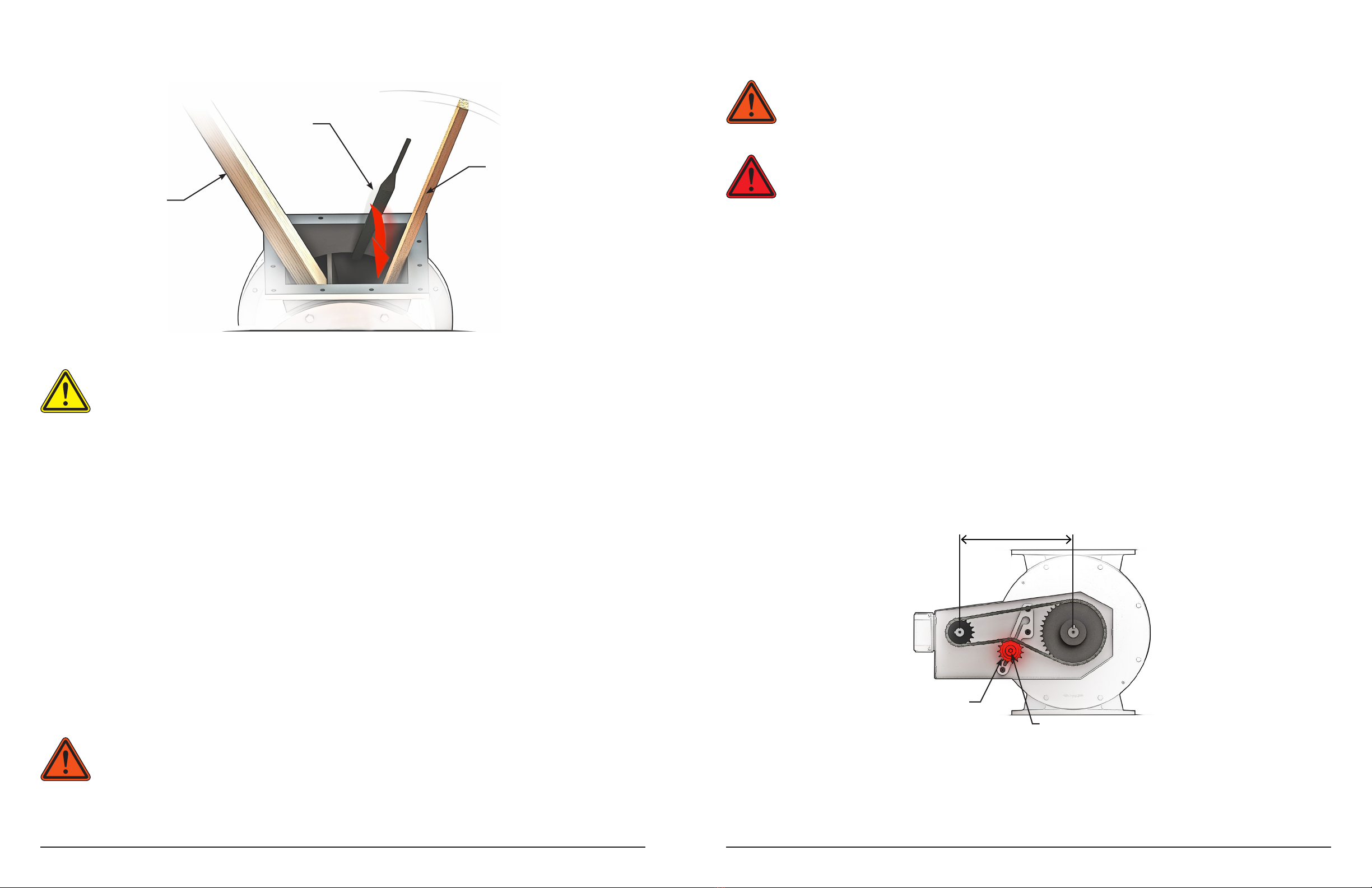
• Never place any part of your body under or near rotating members or moving parts of an airlock.
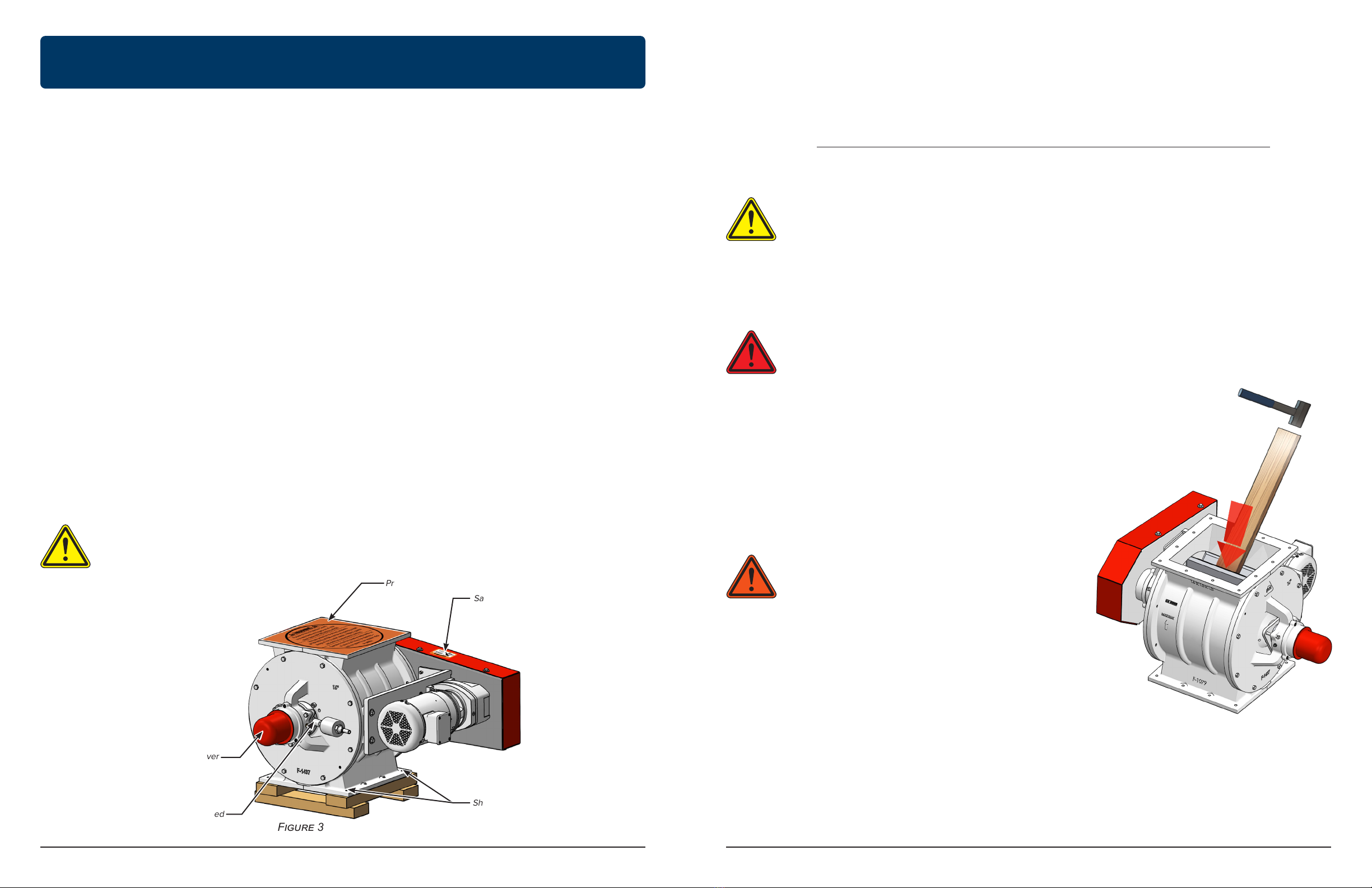
• Never allow any kind of metal or other foreign objects to enter an airlock.
• The rotor of the airlock is built into a housing which has connection flanges for product inlet and product outlet. All
airlock inlet and discharge openings must be completely enclosed, or closed to an adequate length, to prevent human
access to the rotor when the airlock is operating. They must remain enclosed until POWER IS TURNED OFF AND
LOCKED OUT. Keep away from an airlock when it is running.
• Do not manually override or electrically bypass any protective device.
• High voltage and rotating parts can cause series or fatal injury. Only qualified, trained, and experienced personnel
should perform installation, operation, and maintenance of electrical machinery. Make sure the motor and frame of
each airlock is grounded in accordance with OSHA, National Electric Code, and all other applicable regulatory bodies,
including local codes and EN ISO 60204-1 as required for the classified area.
• Operator/installer must ensure that all piping and connections are laid away from equipment access routes and steps.
• If an airlock is equipped with a maintenance panel incorporating any Protective Interlocking Limit Switch (PLS), the PLS
must be interlocked with all electrical controls so that all motors or powered devices on the unit will be de-energized
if any protected cover, guard, grate, or maintenance panel is open or removed. Never attempt to manually override or
electrically bypass the PLS safety device. Interlock function of the PLS must be tested and logged daily by supervisory
personnel.
• Any device powered by air or hydraulic pressure must be equipped with a properly functioning Padlockable Manual
Pressure Lockout and Internal Pressure Relief Valve (PLV) capable of safely relieving motive pressure between the
isolation valve and device.
• Any airlocks used in the processing of combustible materials or in hazardous environments require evaluation by the
owner and regulatory bodies to determine appropriate airlock monitoring equipment, dust control, explosion protection
and electrical equipment enclosures. Do not use an airlock in hazardous environments unless properly equipped for
the hazard.
• Operate safely at all times. Use personal protective equipment (PPE) such as hard hats, helmets, gloves, earplugs,
protective eyewear, etcetera when and where appropriate. Keep PPE in good repair and accessible to aected
personnel.
• Keep the workplace clean and free of dirt and dust at all times. Do not attempt to work on slippery or unsafe surfaces,
ladders or work platforms when maintenance or repair work is being performed on an airlock.
• Do not use a ladder or work platform unless it is in good repair and rated for the load required to complete required
airlock service. Do not exceed maximum load ratings when installing or servicing an airlock.
• Never stand under any kind of hoists or lifting mechanisms whether or not it is loaded or in operation. Never stand
under or near an airlock or component when it is being lifted.
• All airlock lifting devices must be inspected by qualified personnel before each use. Do not use a lifting device to
transport an airlock. Never use a lifting device that is damaged, deteriorated or in need of repair.
• Special attention must be devoted to outside contractors engaged to enter and perform work on an airlock or in the
workplace. Special care must be exercised to ensure all such personnel are fully informed of potential hazards and
plant safety procedures. Special emphasis should be placed on the use of explosion proof electrical, cutting, or welding
tools where required.
• It is ultimately the operator’s responsibility to apply the above listed precautions and ensure proper airlock use,
maintenance and lubrication. Keep these instructions and list of warnings with your machine at all times.
• It cannot be assumed that every acceptable safety procedure is contained herein or that abnormal or unusual
circumstances may not warrant or require additional procedures.

10 11
Kice Industries, Inc. Kice Industries, Inc.
MAN-100-000-007 MAN-100-000-007091123091123
5. DELIVERY INSPECTION AND
INSTALLATION PREPARATION
3. Remove the airlock from the shipping pallet
• Remove shipping bolts securing airlock to the shipping pallet (Figure 3)
• Lift the airlock from the pallet using a tool truck, forklift or lifting gear with sucient lifting
capacity. The airlock should be lifted carefully by the body inlet and/or outlet flange.
• Set the airlock on a clean, smooth level surface.
• Check all bolts to be sure they are installed securely.
4. Inspect the Rotor
• Locate and read all safety decals (Figure 3).
• Remove the protective shipping cover (Figure 3).
• Verify that the rotor rotates freely and check to make sure each rotor
pocket and the interior of the airlock is free of foreign material.
• With the airlock chain not attached, use a soft probe (wood block
or brass rod) and mallet to turn the rotor (Figure 4). If the rotor
turns freely, the inspection is complete. Refer to the maintenance
section of this manual if chain needs disconnected.
• If the rotor does not turn freely or the rotor turns but squeals
loudly, refer to the Maintenance section of this manual.
Figure 4
DANGER: When the protective shipping cover is removed from the airlock, do not place
hands in the airlock or attempt to turn the rotor by hand. Personal injury could occur. Ensure
all personal and foreign objects are clear of the inlet before attempting to turn rotor.
Figure 3
CAUTION: The shaft cover must be in place at all times. If the cover is lost in shipment or
during airlock operation, contact Kice Customer Service Department for replacement.
CAUTION: Do not use rotor shafts, gear motor, motor mount and guards for lifting. Doing so
could aect airlock performance or function.
The airlock has been inspected at Kice and should be in excellent condition upon delivery. A thorough
customer inspection of the airlock should be completed upon receipt to verify its condition.
NOTICE: Delivery inspection should be completed before signing carrier’s release.
When a carrier signs the Kice Industries, Inc. bill of lading, the carrier accepts responsibility for any
subsequent shortages or damage, evident or concealed. Therefore any resulting claim must be made
against the carrier by the purchaser. Evident shortage or damage should be noted on the carrier’s
delivery document before signature of acceptance. Inspection by the carrier for damage, evident or
concealed, must be requested.
1. Complete a visual inspection paying particular attention to guards, protrusions (i.e. gearmotor or
speed reducer, airlock corners, shaft, etc.) and safety decals while the airlock is still secure to the
shipping pallet.
2. Inspect the airlock shaft and seals:
• Remove the shaft cover located on the non-drive end of the shaft and the chain guard (Figure 3).
• Check both ends of the shaft to see if either end has been bent or damaged. If this is the
case, file a claim with the freight company for damages and contact Kice Customer Service
Department.
• Replace the shaft cover and chain guard.
• Be sure that the cover is firmly in place.
• Check VJOT packing gland or dynamic seal.
WARNING: Always wear proper eye protection and
other PPE as required.
5. Inspect the gearmotor or speed reducer if supplied
• Read all the materials supplied with the airlock concerning
the gearmotor or speed reducer.
• Be sure that the drive is securely mounted to the airlock.
• Kice standard Sumitomo Cyclo 6000 gearmotors will be
grease lubricated and require no further action; if other
refer to manufacturer manual.
• If the speed reducer is oil lubricated, add the appropriate
oil as specified by the manufacturer.
Shipping Bolts
Safety Decal
Shaft Cover
Check Dynamic Seal If Provided
Protective Shipping Cover

12 13
Kice Industries, Inc. Kice Industries, Inc.
MAN-100-000-007 MAN-100-000-007091123091123
7. INSTALLATION
If the airlock will not be installed promptly, certain procedures should be followed to ensure acceptable
function upon installation. Below are guidelines which are applicable for standard airlocks. Included
manuals for vendor supplied components supersede the guidelines listed below.
Store in a clean, dry location to prevent rust formation or deterioration.
If the airlock must be stored outdoors, the following precautions should be followed.
• Protect from environment as well as possible by covering to keep out dirt and moisture.
• Store on a skid with a fully covered deck to keep the airlock from resting directly on the ground
ensuring the outlet is covered and protected.
• Securely cover inlet using the steps below.
• Remove shipping cover plate.
• Transfer the position of the airlock flange holes to the shipping cover plate and drill through all
holes.
• Place a gasket on the airlock inlet.
• Bolt shipping cover plate in place by all flange holes.
• Cover motor and drives to prevent ingress of water, dirt and pests.
• If VJOT dynamic seals, plug air hose with appropriate fitting for long term storage.
NOTICE: Turn the rotor a minimum of five revolutions monthly to maintain grease distribution within the
bearings.
1. Move the airlock to the installation area using proper equipment. The airlock should be lifted
carefully by the body inlet and/or outlet flange.
2. Prepare the mounting surfaces to accept the airlock. Equipment should be securely positioned
before accepting an airlock. All mating surfaces should be free of debris, rust and foreign materials.
3. Mount airlock in place.
a. If the airlock will be floor mounted (Figure 5.2), secure to the floor using approved anchors and
then attach the airlock mounting flange to the system flange using fasteners and supplied gasket(s)
(Figure 5).
b. If the airlock connects between two pieces of equipment, and is not floor mounted, attach the
airlock flanges to system flanges using fasteners and supplied gaskets as shown (Figure 5). The
airlock should be attached to the sturdiest equipment first.
4. Tighten all mounting fasteners securely.
5. Connect plant air if equipped. Some outboard airlocks use a pressurized air purge system or a
pressurized shaft seal. Either type will be plumbed at Kice to provide a single compressed air
connection and must be hooked up in order for the airlock to function properly. For dynamic seal
models, the customer will need to supply clean dry air to an air regulator with a maximum pressure
range between 0 - 15 psi. Using a regulator with a range greater than this could result in depleting
the sealant.
Figure 5
6. STORAGE
WARNING: Use appropriate equipment when lifting or moving the airlock. Make sure all
persons and obstructions are clear from the path and installation area. When installing the
equipment, make sure the moving parts inside the equipment are not accessible. This also
fulfills EN ISO 13857 where required.
WARNING: High voltage and rotating equipment can cause serious or fatal injury. Only
qualified, trained and experienced personnel should perform installation, operation and
maintenance of electrical machinery. Ensure the motor and frame of each airlock is
grounded in accordance with OSHA, National Electric Code and all other applicable
regulatory bodies and local codes.
CAUTION: Do not use rotor shafts, gear motor, motor mount and guards for lifting. Doing so
could aect airlock performance or function. NOTICE: If equipped with Air/N2 air regulator, the customer will need to supply clean dry air to an air
regulator with a maximum pressure range between 0 - 30psi. The Air/N2 Regulator should be set to 7
+/- 1psi over conveying pressure.
System Flange
Gasket
Airlock Flange

14 15
Kice Industries, Inc. Kice Industries, Inc.
MAN-100-000-007 MAN-100-000-007091123091123
8. The chain tension should be checked after 48 hours of operation. Refer to the appropriate
maintenance section for recommended chain tensioning procedures. Repeat this step again after
two to three weeks of operation.
SUPPORT FEET
Support feet are provided on airlock valves with bolt on pans. This allows the airlock to be floor
mounted while maintaining clearance between the bolt on pan and the floor. The standard minimum
clearance between the bottom of the bolt on pan and the floor is 1.0” as shown below, unless
otherwise specified. Support feet also provide a stable base for the shipping and handling of
airlocks when bolt on pans are attached. If the airlock will be installed and supported by another
piece of equipment the support feet may be removed after installation.
CAUTION: Kice Industries, Inc. supplies self-lubricated chain on airlocks. Do not oil or
otherwise lubricate.
CAUTION: The pressure regulator should be adjusted so that the purge air pressure
is approximately double that pressure in the pneumatic conveying line and should be
energized prior to handling material. This applies only to lantern ring configurations.
9. On airlocks with outboard bearings which utilize packing, after approximately two hours of
operation, the packing retainers will need to be retightened. This can be done in the following
manner:
a. Use an open-end wrench to tighten the packing retainer bolts (see Figure 5.1).
b. Tighten the bolts until the airlock motor is strained.
c. Then back o the bolts slightly.
10. Some outboard bearing airlocks can
benefit from the use of a pressurized air
purge system or a continuous grease system.
The tapped and plugged hole in both airlock
endplates should be utilized for the air purge
system (see Figure 5.1). This conversion can
be accomplished by replacing the first (inner)
ring of packing in both endplates with a lantern
ring, removing the plug from each endplate,
and attaching a compressed air line equipped
with a pressure regulator to each tapped hole.
To convert an airlock to a continuos grease
system, remove the grease zerk located on
both of the bearing supports and replace with
a grease line (see Figure 5.1)
NOTICE: If installing airlock with dynamic seals, pressures will need to be verified after a run in period
of 2 hours. Check again in 48 hours to confirm correct operation.
Figure 5.2
Figure 5.1
CAUTION: If the motor or speed reducer produces an unusual noise, disconnect the power
and lockout. Then check rotation to be sure motor is not wired backwards.
6. Connect motor to power source.
7. Test run the airlock. If any unusual noises occur, disconnect and lockout the power source. If the
airlock was turning the wrong direction, correct wiring and retest. Refer to Maintenance section
below if the problem persists.
Bolt On Pan
Airlock Flange
Support Foot
1.0” Minimum Clearance to Floor
Bearing Support
Packing Retainer
Grease Zerk
Plug in Airlock Endplate
Packing Retainer Bolt

16 17
Kice Industries, Inc. Kice Industries, Inc.
MAN-100-000-007 MAN-100-000-007091123091123
8. MAINTENANCE
The key to long and trouble-free airlock operation is good maintenance practices. Periodically inspect
the rotor for damage caused by foreign material and for proper rotor placement within the airlock body.
Inspect the bearings and the drive chain for excessive wear. Finally, service the gearmotor or speed
reducer as specified by the original manufacturer.
The majority of airlock operating problems can be traced to improper adjustments and delayed or
neglected maintenance. A consistently applied maintenance program will prevent many problems.
A thorough understanding of the system is required if the operating problems are to be corrected
satisfactorily.
GENERAL ROTOR SERVICE
If the rotor becomes blocked, does not turn freely, or begins to squeal, the rotor should be inspected.
The following steps describe the process required to complete an inspection.
GENERAL MOTOR SERVICE
NOTICE: Not all airlocks use the same motor model. Service instructions and repair components may
vary between models.
Safety, service and repair information for the gearmotor or speed reducer is provided by the
manufacturer. To obtain parts or service for the gearmotor or speed reducer, contact the local dealer
or service representative. If diculty obtaining service or repair components is encountered, please
contact the Kice Customer Service Department for assistance.
WARNING: When performing maintenance, all energy sources associated with the airlock
must be locked and tagged out in compliance with 29 CFR 1910.147, local enforcement
authorities, OSHA, and facility safety practices, before removing any protective cover, guard,
grate or maintenance gate. Removal of transitions which expose hazards such as nip points
of an airlock rotor also require lockout and tagout precautions be employed.
WARNING: Review all Safety Precautions noted in the manual before performing
maintenance on equipment.
NOTICE:
Refer to Appendix 10 for clearance information.
Some applications may require greater rotor
clearance, please contact Kice Sales for assistance if unsure. Not to exceed 0.0079” clearance to
comply with NFPA requirements.
NOTICE: A good rule to follow when troubleshooting a problem is to never make more than one
adjustment at a time, thereby isolating the problem by a process of elimination. The cause of a problem
is usually simple and is easy to pinpoint if you systematically check each system and function.
NOTICE: Severe applications may require adjustments to the maintenance schedule above.
Interval
Task
Daily
Perform a brief inspection. Look and listen for anything out of the ordinary
while the airlock
is running. Adjust VJOT packing retainer as needed.
Biannually
Inspect sprockets and chain for wear. Adjust VJOT packing retainer as needed.
Dynamic seal booster refill / recharge, reset cylinder.
Annually
Inspect rotor for position, wear and damage.
5 years or every
10,000 hours
Replace cartridges, sprockets, chain and dynamic seals.
Manufacturer
recommended
Service gearmotor or speed reducer.
RECOMMENDED MAINTENANCE SCHEDULE - VJOT SERIES
Check cylinder position on dynamic seal.
DANGER: Never place hands or fingers in an airlock unless it has been disconnected and
locked out using wooden blocks and/or probes. These should be placed in the airlock to
prevent the rotor from turning in either direction.
1. Turn o the airlock and remove all potential energy sources following SOPs and lockout/tagout
procedures.
2. Remove the airlock from system to obtain unobstructed access to rotor.
3. Place blocks in the airlock to prevent the rotor from turning unexpectedly (Figure 6).
4. Remove rotor blockage
a. Using a probe, dislodge the obstruction from the rotor and discard.
b. Remove safety blocks.
c. Turn the rotor using the probe to inspect for additional foreign material.
5. Check for rotor damage. If rotor does not turn freely:
a. Locate rotor damage such as burrs or dents on rotor blades.
b. Remove any burrs using a file or emery cloth.
6. If rotor removal is necessary
refer to Rotor Removal
section in this manual.
NOTICE: Use a block or probe robust enough to do the job without damaging or marring the airlock
components.

18 19
Kice Industries, Inc. Kice Industries, Inc.
MAN-100-000-007 MAN-100-000-007091123091123
WARNING: When performing maintenance, all energy sources associated with the airlock
must be locked and tagged out in compliance with 29 CFR 1910.147, local enforcement
authorities, OSHA, and facility safety practices, before removing any protective cover, guard,
grate or maintenance gate. Removal of transitions which expose hazards such as nip points
of an airlock rotor also require lockout and tagout precautions be employed.
WARNING: Review all Safety Precautions noted in the manual before performing
maintenance on equipment.
Chain service life will be maximized when installed and maintained properly. Most chains require
regular lubrication. However, the chain supplied by Kice is factory lubricated and further lubrication is
not needed except in extreme applications. Follow the recommended chain maintenance guidelines
below.
CHAIN MAINTENANCE
NOTICE:
Refer to Appendix 10 for clearance information.
Some applications may require greater rotor
clearance, please contact Kice Sales for assistance if unsure. Not to exceed 0.0079” clearance to
comply with NFPA requirements.
NOTICE:
Refer to Appendix 11 for all torque specifications
.
Figure 6
CAUTION: Remove the minimum amount of material required to eliminate burrs on close
clearance faces of the rotor and body. Proper clearance must be maintained between rotor
blades and the airlock body to retain appropriate function.
NOTICE:
Refer to Appendix 10 for clearance information.
Some applications may require greater rotor
clearance, please contact Kice Sales for assistance if unsure. Not to exceed 0.0079” clearance to
comply with NFPA requirements.
DANGER: Never place hands or fingers in an airlock unless it has been disconnected and
locked out using wooden blocks and/or probes. These should be placed in the airlock to
prevent the rotor from turning in either direction.
NOTICE: The chain tension should be checked after 48 hours of operation. Check it again after two to
three weeks of operation.
Figure 7
1. Turn o airlock and remove all potential energy sources following SOPs and lockout/tagout
procedures before removing chain guard cover.
2. Remove chain by removing connecting link.
3. Confirm the sprockets are in good condition and teeth are not excessively worn.
4. Confirm the chain is free of grit and debris and is in good condition. Pins and bushings should not
have flat surfaces and should release smoothly from each sprocket while in motion.
5. Verify all three sprockets are aligned in the same plane. The idler sprocket will determine the axial
alignment plane.
6. Adjust chain tension to allow chain deflection equal to 2% to 3% of shaft center distance.
Example: Shaft center distance=7 inches →Chain deflection ~.175 inches
a. Loosen nut on idler sprocket.
b. Push idler sprocket up along the slide path to tighten chain (Figure 7).
c. Secure idler sprocket position by tightening the idler sprocket nut.
Remove Burrs or Dents
Using File
Use Soft Probe to
Dislodge Obstruction
Wood Block
Idler Sprocket
Idler Sprocket Nut
Center Shaft Distance

Figure 8
20 21
Kice Industries, Inc. Kice Industries, Inc.
MAN-100-000-007 MAN-100-000-007091123091123
VJOT PACKING GLAND REPLACEMENT NO LANTERN RING
HELPFUL HINT: Working one side of airlock at a time helps keep the rotor centered. If one bearing is
locked at a time, rotor shifting will be limited. If both bearings are loosened rotor will shift from side to
side.
NOTICE: Imperative to keep all sealing components clean through the duration of replacement.
NOTICE:
Refer to Appendix 10 for clearance information.
Some applications may require greater rotor
clearance, please contact Kice Sales for assistance if unsure. Not to exceed 0.0079” clearance to
comply with NFPA requirements.
NOTICE:
Refer to Appendix 11 for all torque specifications
.
NOTICE: Before getting started verify if the airlock needs lantern rings; look for an air regulator leading
to a fitting near the center of the endplate as this is a clear indication. Note that one lantern ring takes
the place of a single packing gland.
COMMON PACKING INSTALLATION MISTAKES
Not keeping sealing surfaces clean
during installation and over tightening
packing retainer.
→ Airlock rotor seizure.
→ Check for product compaction against rotor
hub and endplate.
→ Look for endplate deection when bearing is
tightened down.
→ Loosen packing retainer.
Not tightening down packing retainer. → Premature seal failure. → Ensure packing retainer is tightened down.
Airlock rotor shifting and not checking
clearances (unlocking both bearings at
the same time increase risk of this).
→ Airlock rotor seizure.
→ Rotor and endplate wear.
→ Check all clearances.
→ Do only one bearing at a time.
1. Turn o airlock and remove all potential energy sources following SOPs and lockout/tagout
procedures.
2. Prepare for packing replacement.
a. For Drive Side
i. Remove the chain guard cover.
ii. Loosen idler sprocket to relieve chain tension and remove chain.
iii. Remove driven sprocket and sprocket from airlock gearmotor.
iv. Remove chain guard backplate.
b. For Non-Drive Side
i. Loosen idler sprocket to relieve chain tension and remove chain.
3. Loosen packing retainer bolts (figure 8).
4. Slide packing retainer out of the way towards bearing (figure 8) revealing the packing gland
pocket.
5. Remove old packing. See packing manufacture instructions as needed.
a. Use a flexible packing extractor such as a
Chesterton #253 Flexible Packing Extractor
.
b. Engage the extractor tool into the packing then pull out the packing ring.
c. Repeat steps (a) through (c) until all packing rings are removed from the endplate.
NOTICE: Avoid allowing the extractor tool to contact the rotor shaft. The tool may score the shaft
sealing surface.
6. Clean endplate and shaft ensuring all packing fragments and debris are removed.
7. Inspect shaft sealing surface for damage and wear. Small imperfections may be removed with
emery cloth.
Figure 9
Cut UP Cut UP
Loosen packing retainer bolts
Packing retainer
Cut DOWN

22 23
Kice Industries, Inc. Kice Industries, Inc.
MAN-100-000-007 MAN-100-000-007091123091123
8. Repeat steps 3 through 7 for the opposite endplate.
9. Prepare new rings of packing for installation.
a. If available, use a mandrel or shaft that matches the exact size of the rotor shaft.
b. Cut packing rings at 45° angle.
c. Use a sharp knife. A dull knife will cause the packing to open up making sealing more dicult.
10. Wrap the first ring around the shaft and note the position of the joint (Figure 9).
11. Push the first ring into the packing gland using the packing retainer.
12. Slide packing retainer out of way to access packing gland pocket.
13. Wrap the second ring around the shaft and oset the joint 180° from the position of the first ring
(Figure 9). Push it into the packing gland using the packing retainer then slide packing retainer out
of packing gland pocket.
14. Wrap the third ring around the shaft and oset the joint 180° from the second ring (Figure 9).
Push it into the packing gland pocket using the packing retainer.
15. Evenly tighten the packing retainer bolts until light pressure is applied to packing.
16. Repeat steps 10 through 15 for the opposite endplate.
17. Reattach drive components and guards in the opposite order they were removed.
18. Restore power to airlock with no material passing through the airlock.
19. Equally tighten the bolts until the motor begins to labor.
20. Back o each retainer bolt 1/8 turn.
21. Repeat steps 19 and 20 after two hours of run time.
8" thru 12" 8 ¼" AIRLOCKPACKKIT1
14" thru 20" 10 ¾" AIRLOCKPACKKIT2
24" 12 ⅝" AIRLOCKPACKKIT3
Packing Length
45°
HELPFUL HINT: Working one side of airlock at a time helps keep the rotor centered. If one bearing is
locked at a time, rotor shifting will be limited. If both bearings are loosened rotor will shift from side to
side.
NOTICE: Imperative to keep all sealing components clean through the duration of replacement.
NOTICE:
Refer to Appendix 10 for clearance information.
Some applications may require greater rotor
clearance, please contact Kice Sales for assistance if unsure. Not to exceed 0.0079” clearance to
comply with NFPA requirements.
NOTICE:
Refer to Appendix 11 for all torque specifications
.
VJOT BEARING REMOVAL / REPLACEMENT
COMMON BEARING INSTALLATION MISTAKES
Not keeping bearing and sealing
surfaces clean during installation. → Bearing and rotor seizure. → Check for grease and bearing contamination,
premature bearing wear.
Airlock rotor shifting and not checking
clearances (unlocking both bearings at
the same time increase risk of this).
→ Airlock rotor seizure.
→ Rotor and endplate wear.
→ Check all clearances.
→ Do only one bearing at a time.
→ Ensure bearing is tightened and locked
properly.
1. Turn o airlock and remove all potential energy sources following SOPs and lockout/tagout
procedures.
2. Remove airlock from system to obtain unobstructed access to endplates.
3. Position the rotor so two blades will contact the body once endplates are removed (figure 28).
4. Place blocks in the airlock to prevent the rotor from turning in either direction (figure 6).
5. Remove bearing endcaps from bearing supports as shown (figure 10).
Take care not to damage
lip seal in the bearing end cap.
6. Straighten the bearing lock washer tab engaged with bearing lock nut as shown (figure 11).
7. Using a spanner wrench, remove the bearing lock nut.
8. Slide the bearing lock washer and tongue washer o the rotor shaft.
9. Remove the bolts on ONE endplate.
10. Alternately tighten endplate set screws to move endplate free of the body.
11. Remove endplate carefully from rotor shaft taking care not to drop the bearing or packing retainer
as they are pulled away from the rotor shaft (figure 12).

Figure 10
Figure 12
Figure 14
24 25
Kice Industries, Inc. Kice Industries, Inc.
MAN-100-000-007 MAN-100-000-007091123091123
12. Pull bearing from endplate bearing support (figure 13).
13. Slide bearing spacer out of bearing support (figure 13).
14. Press used radial shaft seal out of bearing support and dispose of properly.
15. Clean endplate and shaft ensuring all packing fragments and debris are removed.
16. Inspect shaft sealing surface and endplate for damage and wear. Small imperfections may
be removed with emery cloth.
17. Verify the grease zerk accepts grease and is clean by pushing a few pumps of grease through
the zerk.
18. Confirm the grease pressure relief valve operates freely.
19. Thoroughly clean interior surfaces of the bearing support and packing gland.
20. Install a new radial shaft seal in bearing support.
21. Loosen the endplate push out set screws positioning them below the endplate mating flange
face.
22. Position packing retainer between bearing support and packing gland.
23. Reinstall endplate with the same caution with which it was removed.
24. Thoroughly clean bearing spacer and slide it into bearing support.
25. Install new bearing until it is firmly in contact with bearing spacer and bearing spacer is pushed
against bearing support step.
NOTICE: The bearing does not require the assistance of tools to install when properly aligned. Please
refrain from striking the bearing to prevent bearing damage which will decrease service life.
NOTICE: TIMKEN bearings must be replaced with the EXACT SAME PART NUMBER. No substitutions
allowed.
26. Work grease into all bearing cone voids and push into bearing cone.
27. Slide tongue washer and bearing lock washer over shaft with respective tabs in shaft keyway
until tongue washer contacts the bearing.
28. Hand tighten bearing locknut against bearing lock washer.
29. Repeat steps 4 through 28 for the opposite endplate.
30. Verify clearance using feeler gauges that ensure the rotor turns freely (figure 14).
31. Install a new radial shaft seal in the bearing end cap.
32. Install bearing end cap.
Figure 11
Bearing end cap Bearing locknut
Bearing lockwasher
Figure 13
Remove endplate from rotor shaft Remove bearing
Bearing spacer
Ensure Clearances are Set Between
Rotor, Body, and Endplates
Feeler Gauge

26 27
Kice Industries, Inc. Kice Industries, Inc.
MAN-100-000-007 MAN-100-000-007091123091123
33. If necessary, install new packing following the Packing Gland Replacement instructions (see
page 20).
34. Reattach drive components and guards in the opposite order they were removed.
NOTICE: Confirm each grease pressure relief valve operates freely before adding grease to bearings.
NOTICE: The booster regulator assembly is standard.
NOTICE: The Air/N2 Regulator Assembly does
not come standard. This can be added as an
option.
1. Verify the plant air pressure supplied by the regulator is at least 2 psig greater than conveying
pressure.
2. With an open-end wrench alternately tighten the packing retainer bolts 1/8 turn at a time as shown
(Figure 8).
3. Equally tighten the bolts until the motor begins to labor.
4. Back o each retainer bolt 1/8 turn.
5. With no material passing through the airlock, confirm plant air is being delivered to the lantern
ring.
LANTERN RING SEAL MAINTENANCE
BOOSTER REGULATOR MAINTENANCE
Air/N2 MAINTENANCE LANTERN RING SEAL REPLACEMENT
Optional lantern ring seals are used when purge air is applied to sweep debris from the rotor shaft and
are sealed on the back side with two rings of braided packing. Because the air is added to the product
stream, it should be clean dry air and some installations may require sterile air.
Clean dry air is to be supplied to the air regulator.
The Booster regulator should have a maximum
pressure range between 0 - 15psi. The booster
Regulator should be set to a constant pressure of
around 7psi.
Clean dry air is to be supplied to the air regulator.
The Air/N2 regulator should have a maximum
pressure range between 0 - 30psi. The Air/
N2 Regulator should be set to 7 +/- 1psi over
conveying pressure.
Inspect and adjust packing retainers as needed after two hours of operation then about every month
or 200 hours thereafter using the following steps.
WARNING: Failure to supply plant air to seals before allowing material to pass through the
airlock will result in premature seal failure and shaft damage.
CAUTION: Proper compression of the packing will prevent shaft damage. Loose packing
may allow plant air to leak to atmosphere rather than being directed towards the rotor and
cause debris to accumulate in the lantern ring thereby scoring the rotor shaft. Conversely,
excessively tight packing may cause the packing itself to wear grooves into the rotor shaft.
COMMON LANTERN RING SEAL REPLACEMENT MISTAKES
Improper lantern ring air, start process, or
poor to no air.
→ Lantern ring blinds over with
product.
→ Verify air regulation and quality. Verify lantern
ring is purging air prior to beginning process.
NOTICE:
Refer to Appendix 10 for clearance information.
Some applications may require greater rotor
clearance, please contact Kice Sales for assistance if unsure. Not to exceed 0.0079” clearance to
comply with NFPA requirements.
NOTICE:
Refer to Appendix 11 for all torque specifications
.
NOTICE: The rotor can shift during bearing replacement. Rotor clearance must be verified after
replacement. Less than minimum recommended clearance can cause premature wear or failure.
Always verify clearances before operation.
Air/N2 Regulator Assembly
Booster Regulator Assembly

28 29
Kice Industries, Inc. Kice Industries, Inc.
MAN-100-000-007 MAN-100-000-007091123091123
24. Follow Packing Replacement –
see page 20.
25. Repeat steps 4 through 23 for the opposite endplate.
26. Supply plant air to lantern rings.
NOTICE: One lantern ring takes the place of a single packing gland.
7. Position the rotor so two blades will contact the body once endplates are removed (Figure 28).
8. Place blocks in the airlock to prevent the rotor from turning in either direction (figure 6).
9. Remove bearing endcaps from bearing supports as shown (figure 10).
Take care not to damage
lip seal in the bearing end cap.
10. Straighten the bearing lock washer tab engaged with bearing lock nut as shown (figure 11).
11. Using a spanner wrench, remove the bearing lock nut.
12. Slide the bearing lock washer and tongue washer o the rotor shaft.
13. Remove the bolts on ONE endplate.
14. Alternately tighten endplate set screws to move endplate free of the body.
15. Remove endplate carefully from rotor shaft taking care not to drop the bearing or packing
retainer as they are pulled away from the rotor shaft (figure 12).
16. Remove used lantern ring from the endplate and dispose of properly.
17. Clean packing gland and shaft ensuring all packing fragments and debris are removed.
18. Inspect shaft sealing surface and packing gland for damage and wear. Small imperfections may
be removed with emery cloth.
19. Insert new lantern ring into packing gland with the chamfered edge facing the rotor (Figure 15). A
stamped “R” may additionally be found on the rotor facing side of the lantern ring.
20. Remove the endplate push out set screws so that they do not protrude out of the endplate
mating flange face.
21. Reinstall endplate with the same caution with which it was removed.
22. Follow instructions provided to set Rotor Clearance – OT Series.
23. Prepare two new rings of packing for installation.
HELPFUL HINT: Working one side of airlock at a time helps keep the rotor centered. If one bearing is
locked at a time, rotor shifting will be limited. If both bearings are loosened rotor will shift from side to
side.
NOTICE: Imperative to keep all sealing components clean through the duration of replacement.
1. Turn o airlock and remove all potential energy sources following SOPs and lockout/tagout
procedures.
2. Remove airlock from system to obtain unobstructed access to endplates.
3. Prepare for lantern seal ring replacement.
a. For Drive Side
i. Remove the chain guard cover.
ii. Loosen idler sprocket to relieve chain tension and remove chain.
iii. Remove driven sprocket and sprocket from airlock gearmotor.
iv. Remove chain guard backplate.
b. For Non-Drive Side
i. Loosen idler sprocket to relieve chain tension and remove chain.
4. Loosen packing retainer bolts (figure 8).
5. Slide packing retainer out of the way towards bearing (figure 8) revealing the packing gland
pocket.
6. Remove old packing. See packing manufacture instructions as needed.
a. Use a flexible packing extractor such as a
Chesterton #253 Flexible Packing Extractor
.
b. Engage the extractor tool into the packing then pull out the packing ring.
c. Repeat steps (a) through (c) until all packing rings are removed from the endplate.
NOTICE: Avoid allowing the extractor tool to contact the rotor shaft. The tool may score the shaft
sealing surface.
DANGER: Never place hands or fingers in an airlock unless it has been disconnected and
locked out using wooden blocks and/or probes. These should be placed in the airlock to
prevent the rotor from turning in either direction.
Figure 15
Lantern Ring Seal
Packing

Figure 16 Figure 17
30 31
Kice Industries, Inc. Kice Industries, Inc.
MAN-100-000-007 MAN-100-000-007091123091123
VJOT DYNAMIC SEAL MAINTENANCE
The Kice VJOT Airlock with dynamic seal is designed and
tested to the most demanding conditions. To keep the VJOT
dynamic seal in service for as long as possible, the seal should
be inspected and checked per the maintenance schedule
below. Should a repair be needed for the dynamic seal the unit
can be disassembled from the airlock and shipped back to Kice
for repair or rebuild.
MAINTENANCE SCHEDULE FOR VJOT DYNAMIC SEAL
Daily
Perform a brief inspection. Look and listen for anything out of the ordinary while the
airlock is running. Look for leaks from the dynamic seal booster's air pipe to the air
source.
Biannually Check to see if dynamic seal booster needs recharged or reset. If yes, follow
recharge instructions.
2 years Inspect and rebuild dynamic seal (Kice is the only authorized seal re-builder).
DYNAMIC SEAL REMOVAL & REPLACEMENT
HELPFUL HINT: Working one side of airlock at a time helps keep the rotor centered. If one bearing is
locked at a time, rotor shifting will be limited. If both bearings are loosened rotor will shift from side to
side.
NOTICE: Imperative to keep all sealing components clean through the duration of replacement.
NOTICE:
Refer to Appendix 10 for clearance information.
Some applications may require greater rotor
clearance, please contact Kice Sales for assistance if unsure. Not to exceed 0.0079” clearance to
comply with NFPA requirements.
NOTICE:
Refer to Appendix 11 for all torque specifications
.
COMMON SEAL REPLACEMENT MISTAKES
Not keeping sealing surfaces clean
during installation, loose seal ange, or
protruding seal bolts past the endplate
surface.
→ Airlock rotor seizure.
→ Check for product compaction against rotor
hub and endplate.
→ Look for endplate deection when bearing is
tightened down.
→ Tighten seal ange securely.
→ Insuring fasteners don't extend beyond
inboard side of the endplate.
Not locking seal to rotor shaft. → Premature seal failure. → Ensure seal is fastened to rotor shaft.
Airlock rotor shifting and not checking
clearances (unlocking both bearings at
the same time increase risk of this).
→ Airlock rotor seizure.
→ Rotor and endplate wear.
→ Check all clearances.
→ Do only one bearing at a time.
Too much air pressure on seals. → Booster sealant depletes
prematurely.
→ Ensure regulator before seals has a set range
no greater than 0 - 15 psi.
→ Ensure pressure is a constant pressure of
approximately 7 psi.
1. Turn o airlock and remove all potential energy sources following SOPs and lockout/tagout
procedures.
2. Prepare for packing replacement.
a. For Drive Side
i. Remove the chain guard cover.
ii. Loosen idler sprocket to relieve chain tension and remove chain.
iii. Remove driven sprocket and sprocket from airlock gearmotor.
iv. Remove chain guard backplate.
b. For Non-Drive Side
i. Loosen idler sprocket to relieve chain tension and remove chain.
Shaft Guards Set screws

Figure 22
32 33
Kice Industries, Inc. Kice Industries, Inc.
MAN-100-000-007 MAN-100-000-007091123091123
12. Thoroughly clean interior surfaces of the endplate and flange area for dynamic seal.
13. Install new or rebuilt dynamic seal from the inside face of the endplate. Verify that O-rings are
in place for both shaft (inner diameter) and the gland O-ring that forms the seal on the inside face
of the endplate. Lightly lubricate each O-ring to prevent damage or rolling during assembly. Insure
PTFE ring is properly seated and flush with seal flange before continuing installation (figure 21).
14. Install mount bolts from endplate to dynamic seal (figure 20). Cross tighten the three bolts.
15. Remove the endplate push out set screws so that they do not protrude out of the endplate
mating flange face.
16. Reinstall endplate with the same caution with which it was removed.
NOTICE: Make sure orientation of dynamic seal will allow for the booster and air flush nozzle to be
installed.
3. Shuto / disconnect plant air to seals.
4. Remove shaft guards to gain access to set screws (figure 16).
5. Loosen all set screws (figure 17).
6. Remove the endplate from the airlock (figure 18).
7. Remove air flush nozzle from dynamic seal (figure 19).
8. Remove booster/cylinder assembly from the dynamic seal (figure 19).
9. Remove the three dynamic seal mount bolts from the airlock endplate (figure 20).
10. Remove the dynamic seal from the endplate (figure 21).
11. Send dynamic seal to Kice Industries for any major repairs or for a complete rebuild.
17. Verify clearance using feeler gauges that ensure the rotor turns freely (Figure 22).
18. Once clearances are verified, alternatively tighten the setscrews on the dynamic seal (figure 17).
19. Reinstall air flush nozzle and booster/cylinder assembly (figure 19).
20. Reinstall shaft guards (figure 16).
21. Turn on / connect plant air to seals.
22. Reattach any drive components and guards in the opposite order they were removed.
Figure 18 Figure 19
Remove Endplate Air Flush Nozzle
Booster / Cylinder
Figure 20 Figure 21
Mount Bolts Seal Flange PTFE Ring
Dynamic Seal Mounts to Inside of Endplate
Ensure Clearances are Set Between
Rotor, Body, and Endplates
Feeler Gauge

Figure 24 Figure 25
34 35
Kice Industries, Inc. Kice Industries, Inc.
MAN-100-000-007 MAN-100-000-007091123091123
DYNAMIC SEAL BOOSTER RECHARGING
VISUAL INSPECTION OF DYNAMIC
SEAL BOOSTER
1. Disconnect supply air to dynamic seal. Note the airlock can stay running during recharge.
2. Remove the clear protective tubing (figure 24).
3. Un-thread the booster/cylinder from the booster pipe (figure 25).
4. Fill the empty booster pipe with PTFE putty or replace empty booster pipe with new pre-filled one
(figure 26).
5. Manually push the cylinder back into the housing. The gauge rod should now be visible (figure
27).
6. Thread booster/cylinder back onto booster pipe.
7. Reconnect protective clear tubing.
8. Re-supply air to dynamic seals.
If the gauge rod has minimal visibility this indicates a
booster recharge is needed (figure 23). If gauge rod is
visible than no further action is needed.
The booster on the dynamic seal should be checked every 6-months for possible sealant recharging. If
a recharge is needed the gauge will not be visible (figure 23). Follow the steps below to recharge the
booster.
Prelled Sealant Pipes 100-131-331
1000ML Tub of Food Grade Sealant 100-131-330
200ML Tub of Food Grade Sealant 100-131-329
PTFE SEALANT OPTIONS
NOTICE: Booster sealant should not deplete quicker
than 4-6 Months (depending on application). If depeltion
is occuring is the case verify air regulator has at a
maximum service range between 0 - 15 psi and pressure
constant around 7 psi.
Figure 23
Gage not visible, recharge needed
Fully charged state
Figure 26 Figure 27
Clear Tubing Booster Pipe Booster / Cylinder
Push Cylinder InFill with PTFE Putty Visible Gage Rod

36 37
Kice Industries, Inc. Kice Industries, Inc.
MAN-100-000-007 MAN-100-000-007091123091123
NOTICE:
Refer to Appendix 10 for clearance information.
Some applications may require greater rotor
clearance, please contact Kice Sales for assistance if unsure. Not to exceed 0.0079” clearance to
comply with NFPA requirements.
ADJUSTING AIRLOCK CLEARANCES
1. Turn o airlock and remove all potential energy sources following SOPs and lockout/tagout
procedures.
2. Using a feeler gauge, check the clearance between the rotor and the end plates (figure 22).
There should be minimum clearance of 0.003”. Refer to Appendix 10 for clearance information as
these may vary depending on operating temperature and valve size.
3. Remove the chain guard, the drive chain, the sprocket and the bushing on the airlock shaft, the
sprocket on the reducer shaft, the chain guard backplate, and the shaft cover.
4. Remove both end caps from the bearing supports.
5. Clean the grease from the bearing assemblies.
6. Straighten the lock washer tab from the slot on both adjusting nuts.
7. Using a spanner wrench, loosen one adjusting nut while tightening the other. To increase the
internal clearance between the rotor and the near side end plate, loosen (CCW) the adjusting nut on
the near side while tightening the adjusting nut on the far side. To decrease the internal clearance
between the rotor and the near side end plate, perform the operation in reverse.
8. When the desired internal clearance is achieved, bend down the lock washer tabs to lock the nuts
in place.
9. Reinstall the end caps onto the bearing supports after packing void with fresh grease.
10. Reinstall the chain guard backplate, the sprocket and bushing on the airlock shaft, the sprocket
on the reducer shaft, the drive chain, the chain guard, and the shaft cover.
NOTICE: `The serial number is stamped into the body on the drive end side opposite the motor and
speed reducer.
REMOVING ROTOR
To remove the rotor:
1. Turn o airlock and remove all potential energy sources following SOPs and lockout/tagout
procedures.
2. Remove airlock from system to obtain unobstructed access to rotor through the inlet of the
airlock.
3. Place a block in the airlock to prevent the rotor from turning unexpectedly (Figure 6).
4. Prepare drive side.
a. Remove the chain guard cover.
b. Loosen idler sprocket to relieve chain tension and remove chain.
c. Remove drive sprocket and sprocket from airlock rotor.
d. Remove chain guard backplate.
5. Remove shaft cover opposite the drive side.
6. Match mark each endplate and body flange to
ensure they are installed in the same position from
which they were removed.
7. Position the rotor so two blades will contact the
body on each side while being removed (Figure 28).
8. Remove both bearings as noted in the Bearing
Replacement – section above.
9. Remove the bolts on one endplate.
10. Alternately tighten endplate push out set screws to
move endplate free of the body.
11. Remove endplate taking care not to hit rotor shaft to prevent damage. Complete a visual
inspection for wear and damage.
12. The rotor may be pulled from the body. If additional assistance is required, use a rawhide
hammer to firmly rap on the rotor shaft protruding through the opposite endplate.
13. Visually inspect the body bore for wear and damage.
14. Remove the endplate push out set screws so that they do not protude out of the endplate mating
flange face.
15. Reinstall the rotor and endplate with the same caution with which they were removed.
16. Install bearings as noted in the Bearing Replacement Section –
see page 24
.
17. Using a feeler gauge, check the clearance between the rotor and the airlock end plates (Figure 22).
18. Reattach drive components and guards in the opposite order they were removed.
Figure 28
NOTICE:
Refer to Appendix 10 for clearance information.
Some applications may require greater rotor
clearance, please contact Kice Sales for assistance if unsure. Not to exceed 0.0079” clearance to
comply with NFPA requirements.
NOTICE:
Refer to Appendix 11 for all torque specifications
.

1
38 39
Kice Industries, Inc. Kice Industries, Inc.
MAN-100-000-007 MAN-100-000-007091123091123
Drives are not shown for VJOT airlocks due to historic variations in selection. Please contact Kice
Industries, Inc. for drive related questions and provide the representative the airlock job number, serial
number and any known post production modifications.
EXPLODED VIEW OT SERIES
seziSelbacilppA#traPeciKnoitpircseDnoollaB
SMALL BODY AIRLOCK PACKING AIRLOCKPACKKIT1 8" thru 12"
MEDIUM BODY AIRLOCK PACKING AIRLOCKPACKKIT2 14" thru 20"
LARGE BODY AIRLOCK PACKING AIRLOCKPACKKIT3 24"
"21urht"80212-8092-VARGNIRNRETNALKCOLRIAYDOBLLAMS
MEDIUM BODY AIRLOCK LANTERN RING RAV-2914-2120 14" thru 20"
"420212-8192-VARGNIRNRETNALKCOLRIAYDOBEGRAL
SHAFT GUARD W ROTATING PARTS WARNING DECAL SO Sha� Guard
EMC253X2 8" thru 12"
SHAFT GUARD W ROTATING PARTS WARNING DECAL LO SHAFT GUARD
EMC253X2 14" thru 24"
4"42URHT"8M8241-FPACDNE
CR15241 8" thru 12"
CR21759 14" thru 24"
N-09 8" THRU 12"
N-13 14" THRU 24"
TW109 8" THRU 12"
TW-113 14" THRU 24"
K-91509 8" THRU 24"
K-91513 14" THRU 24"
394A-396 8" THRU 24"
394A - 395A 14" THRU 24"
10 "42URHT"80232-0092-VARRECAPSGNIRAEB
CR19607 8" thru 12"
CR26123 14" thru 20"
CR33645 24"
SMALL BODY AIRLOCK PACKING RETAINER F-1430M-1 8" thru 12"
MEDIUM BODY AIRLOCK PACKING RETAINER F-1430M-2 14" thru 20"
LARGE BODY AIRLOCK PACKING RETAINER F-1430M-3 24"
BEARING LOCK NUT6
3
1
2
5END CAP RADIAL SHAFT SEAL
BEARING SUPPORT RADIAL SHAFT SEAL11
12
BEARING LOCK WASHER7
TONGUE WASHER8
9BEARING ASSEMBLY
8" thru 12" 8 ¼" AIRLOCKPACKKIT1
14" thru 20" 10 ¾" AIRLOCKPACKKIT2
24" 12 ⅝" AIRLOCKPACKKIT3
PACKING KITS
Table of contents
Other KICE Industrial Equipment manuals
Popular Industrial Equipment manuals by other brands

Westfalia
Westfalia 838195 Original instructions

V.ORLANDI
V.ORLANDI GA 38 Installation, use and maintenance instructions

HYDAC FILTER SYSTEMS
HYDAC FILTER SYSTEMS CMP 43x0-5 Series Installation and maintenance instructions

KLOBER
KLOBER Venduct System installation instructions

GENERAL RADIO COMPANY
GENERAL RADIO COMPANY 874-GAL operating instructions

morse
morse 405M-114 Operator's manual