8Eclipse ThermJet PCA, V2, Design Guide 206, 6/4/2010
NOTE: The stated operational characteristics only apply if
the described control circuits are followed. Use of different
control methods will result in unknown operational
performance characteristics. Use the control circuits
contained within this section or contact Eclipse for written,
approved alternatives.
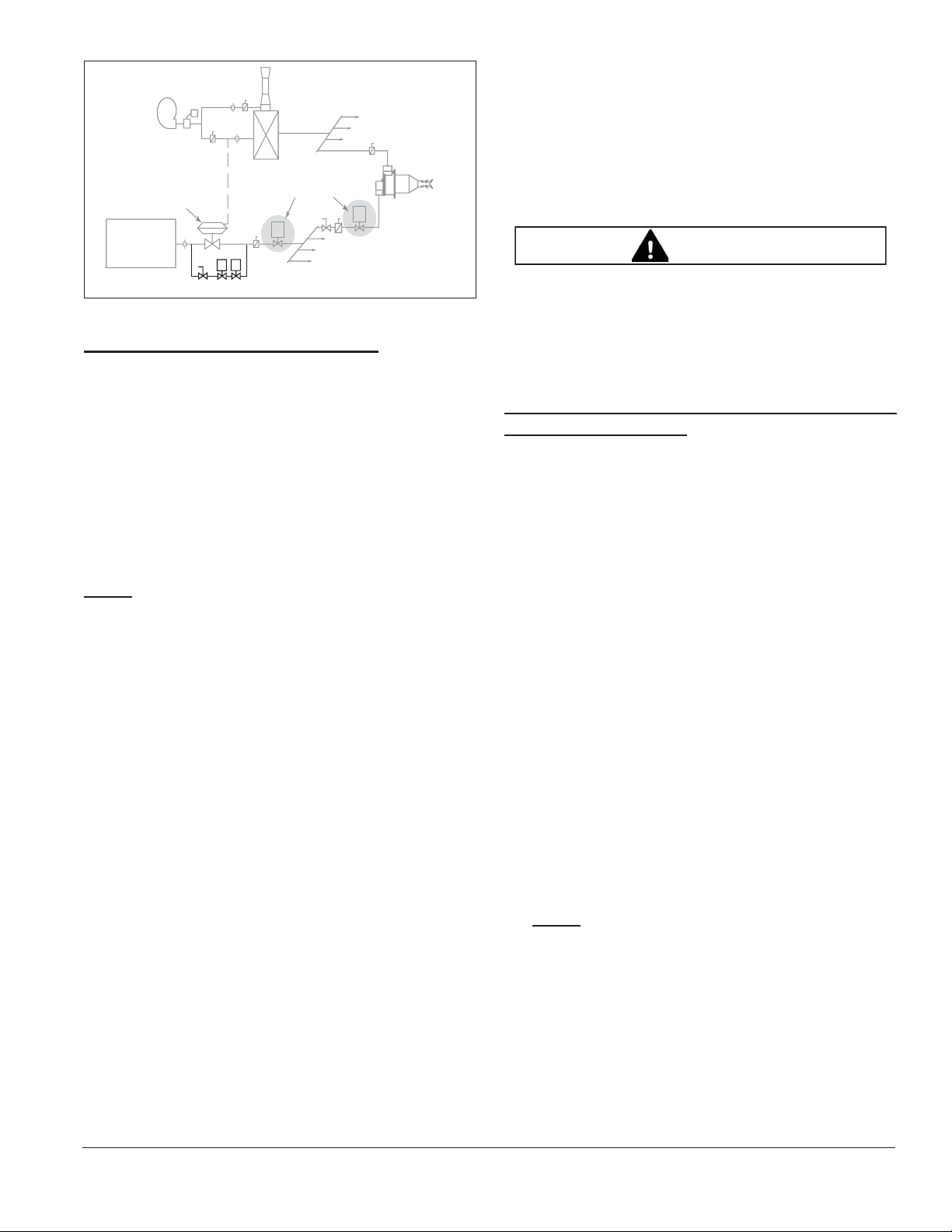
In Figure 3.2 there are schematics of these control
methods. The symbols in the schematics are explained in
the “Key to System Schematics” (see Appendix, page 13).
Automatic Gas Shut-Off by Burner or
Shut-Off by Zone
The automatic gas shut-off valve can be installed in two
operational modes:
Automatic gas shut-off by burner
If the flame monitoring system detects a failure, the
gas shut-off valves close the gas supply to the burner
that caused the failure.
Automatic gas shut-off by zone
If the flame monitoring system detects a failure, the
gas shut-off valves close the gas supply to all the
burners in the zone that caused the failure.
NOTE: All ThermJet PCA control schematics reflect a
single gas automatic shut-off valve. Each schematic
shows both operational modes. Only one is necessary.
This may be changed to conform to local safety and/or
insurance requirements (Refer to ThermJet Installation
Guide No. 206).
Modulating Gas & Air
On-ratio control or excess air @ low fire
A burner system with modulating control gives an input
that is in proportion with the demands of the process. ANY
input between high and low fire is possible.
1. Air
The control valve Xis in the air line. It can modulate
air flow to any position between low and high fire air.
2. Gas
The ratio regulator Yallows the on-ratio amount of
gas to go to the burner. Low fire gas is limited by the
ratio regulator Y. High fire gas is limited by the
manual butterfly valve Z.
NOTE: The ratio regulator can be biased to give excess
air at low fire.
NOTE: Do not use an adjustable limiting orifice (ALO) as
the high fire gas limiting valve Z. ALO’s require too much
pressure drop for use in a proportional system.
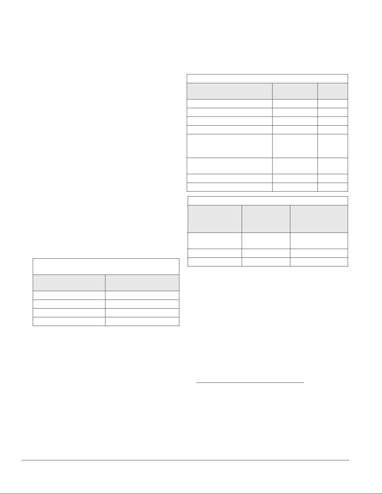
Step 3: Ignition System
For the ignition system use:
• 6,000 VAC transformer
• Full-wave spark transformer
• One transformer per burner
DO NOT USE:
• 10,000 VAC transformer
• Twin outlet transformer
• Distributor type transformer
• Half-wave transformer
It is recommended that low fire start be used. However,
ThermJet PCA burners are capable of direct spark ignition
anywhere within the specified ignition zone (see
Datasheets 206-1 through 206-13).
NOTE: You must follow the control circuits described in
the previous section, “Control Methodology,” to obtain
reliable ignition. Local safety and insurance require limits
on the maximum trial for ignition time. These time limits
vary from country to country.
The time it takes for a burner to ignite depends on:
• The distance between the gas shut-off valve and the
burner
• The air/gas ratio
• The gas flow at start conditions
It is possible to have the low fire too low to ignite within the
trial for ignition period. Under these circumstances you
must consider the following options:
• Start at higher input levels
• Resize and/or relocate the gas controls
• Use bypass start gas
Bypass Start Gas (Optional)
A bypass start gas circuit provides gas flow around zone
gas control valves during the trial for ignition period. This
should only be used if excess air is being used on low fire;
it should NOT be used with on-ratio low fire systems.
During the trial for ignition period, the solenoid valve in the
bypass line plus the automatic gas shut-off valve (either at
each burner or each zone) are opened. If a flame is
established, the bypass solenoid valve closes at the end
of the trial for ignition period. If a flame is not established,
then the bypass solenoid valve and the automatic gas
shut-off valve closes.