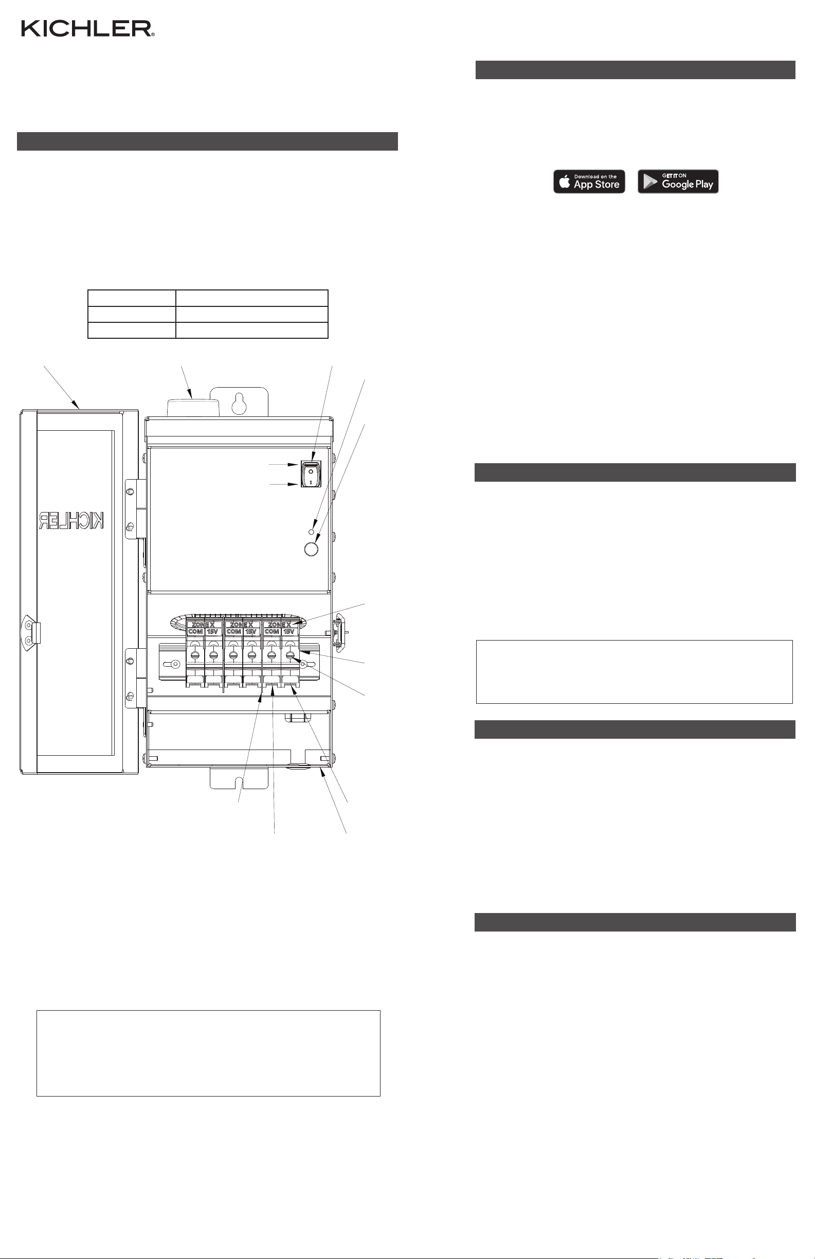
CABLE ENTRY
FOR 15V
For warranty information please visit: kichler.com/warranty IS-15SCT300SS-USREV 3-MAR-2023
We’re here to help 866-558-5706
Hrs: M-F 9am to 5pm EST
PAGE 2
PLEASE READ ALL WARNING AND CAUTION STATEMENTS
AND COMPLETE ALL INSTALLATION INSTRUCTIONS
ON PAGE 1 BEFORE FOLLOWING
INSTALLATION INSTRUCTIONS ON PAGE 2
If the unit cycles on and o without regard to the timer setting or other controls,
it should be checked by a qualified service person.
• Circuit breaker on the Secondary / 15V side will trip if there is a short or if total
wattage installed exceeds rated wattage per circuit. To reset breaker, flip switch
to “OFF” then back to “ON” position.
• Thermal protector on the Primary / 120V side will shut o unit if overheated.
INSTALLATION INSTRUCTIONS (CONTINUED)
6. Split Kichler SPT Direct Burial Wire 12/2 or 10/2 cable approximately 3” (76 mm), and strip
1/2” (12 mm) insulation o each wire. 12/2 and 10/2 cable is the heavy black cable with
which all Kichler® 12-volt low voltage lighting fixtures will be connected.
(Reference “Direct Burial 2 Conductor SPT Cable” chart on Page 1 for description and
part numbers).
7. Choose a zone number. On the bottom of the terminal block [E] push conductor of
one or more wire runs (up to the Max. number of conductors, refer to chart below)
to be controlled by this zone number into the hole marked “COM” and tighten the
corresponding screw on terminal block face until wire is secure. Torque terminal blocks
screws to 32 - 35 lb-in (3.6 - 4.0 N-m). See chart for maximum wire sizes based on gauge:
Wire Gage Size Max. number of conductors
#12 6
#10 3
8. For more information on voltage drop, consult the Kichler Landscape Lighting Catalog,
or contact your local Kichler distributor.
• Push remaining bare wire into the hole marked 15V on bottom of terminal block and
tighten the corresponding screw on terminal block face until wire is secure. Again,
refer to the torque specifications in Step 7. Ensure that the insulation is not under the
terminal plate. Check all connections after installation. See “Risk of Fire” warnings in
“CAUTIONS” section of this instruction guide.
9. Plug power supply cord into standard 120 volt receptacle.
NOTE: The power supply cord must be plugged into a weather tight receptacle
equipped with a Ground Fault Interrupter (GFCI).
LED INDICATOR
CIRCUIT BREAKER
TERMINAL
BLOCKS [E]
TIGHTENING
SCREW
CABLE ENTRY
FOR COMMON
REMOVABLE DOOR ANTENNA
DIVIDER [F]
PULLABLE
ENDCAP
PAIRING BUTTON
QUICK START APP SETUP INSTRUCTIONS
NOTE: Wi-Fi must be used for initial app setup and registration.
Helpful Hint: For initial software setup, plug transformer into an outlet
near the Wi-Fi router, then move to it’s permanent location once initial
setup has been completed.
1. Download the Kichler Connects™App on the Apple® App Store® or on
Google Play™.
MANUAL MODE
If both Wi-Fi and Bluetooth connectivity is lost, you can still turn
your lights on and o without an app:
1. To manually turn on all lights connected to the transformer, press the
pairing button on the transformer 3 times (quickly).
2. To manually turn o all lights connected to the transformer, flip the
circuit breaker switch on the transformer to “OFF”.
3. To manually turn all lights back on again, flip the circuit breaker switch to
“ON”, then press the pairing button 3 times (quickly).
NOTE: Once Wi-Fi or Bluetooth connectivity is restored, make sure that
the circuit breaker switch on the transformer is set to “ON”, then open
the Kichler Connects™ app.
2. Open the Kichler Connects™ app. Register your account if you are a first-
time user.
Make sure your device’s Wi-Fi and Bluetooth are turned on, and that you
are in range of the Wi-Fi router.
3. On the front of the transformer, press and hold the pairing button down
for 5 seconds until the LED indicator light on the transformer starts to
blink red.
4. In the app, select “Add Device” or select the (+) button on the top right,
and then select “Add Manually” and the Smart Transformer icon or select
“Auto Scan” for device. Follow app prompts to add device.
5. “Enter Wi-Fi password” by selecting your 2.4GHz channel. Then enter
your password and press “Next”.
6. Once connected, you can rename the device by clicking the pencil icon, if
desired. Then push “Done”.
7. Your device is now ready to use. Tap the “Power On/O” button to
control your landscape lighting, or select a preset schedule. While on the
Smart Transformer device screen, select “Timer” on the bottom right.
Next simply select your preferred preset schedule.
To learn more visit Kichler.com/kichler-connects
OFF
ON
ZONE NUMBER
FCC INFORMATION
© 2022 Kichler Lighting LLC. All rights reserved. Kichler Connects™ is a trademark of Kichler
Lighting LLC.
Amazon Alexa is a trademark of Amazon.com, Inc.,
Apple, App Store, and the Apple logo are registered trademarks of Apple Inc.,
Bluetooth® word mark and logos are registered trademarks owned by Bluetooth SIG, Inc.,
The Google Home logo, Google Play, and the Google Play logo, are trademarks of Google
LLC, and
Wi-Fi® is a registered trademark of the Wi-Fi Alliance.
ISEDC INFORMATION
ISEDC Warning:
This device complies with Innovation, Science and Economic Development Canada licence-exempt RSS standard(s).
Operation is subject to the following two conditions:
1. This device may not cause interference, and
2. This device must accept any interference, including interference that may cause undesired operation of the
device.
Le onjunc areil est conforme aux CNR d’ l’innovation, la science et le développement économique Canada licables aux
areils radio exempts de licence. L’exploitation est autorisée aux deux conditions suivantes :
1. L’areil ne doit pas produire de brouillage, et
2. L’utilisateur de l’appareil doit accepter tout brouillage radioélectrique subi, onj si le brouillage est susceptible
d’en compromettre le fonctionnement.
Any changes or modifications not expressly approved by the party responsible for compliance could void the user’s
authority to operate the equipment.
Tous les changements ou modifications non expressément approuvée par le responsible de la conformité pourrait
vider l’utilisateur est habilité à exploiter l’équipemen.
ISEDC Radiation Exposure Statement:
This equipment complies with ISEDC RF radiation exposure limits set forth for an uncontrolled environment. This
transmitter must not be co-located or operating in conjunction with any other antenna or transmitter.
Cet appareil est conforme aux limitesd’exposition de rayonnement RF ISEDC établiespour un environnement
non contrôlé. Cetémetteur ne doit pas être co-implanté oufonctionner en onjunction avec toute autreantenne ou
transmetteur.
This equipment should be installed and operated with minimum distance 20cm between the radiator& your body.
La distance entre le radiateur et le corps doit être d’au moins 20 cm lors de l’installation et du fonctionnement de
cet appareil.
FCC Warning:
This device complies with part 15 of the FCC Rules. Operation is subject to the following two conditions:
1. This device may not cause harmful interference, and
2. This device must accept any interference received, including interference that may cause undesired
operation.
Any changes or modifications not expressly approved by the party responsible for compliance could void the
user’s authority to operate the equipment.
Note: This equipment has been tested and found to comply with the limits for a Class B digital device, pursuant to
part 15 of the FCC Rules. These limits are designed to provide reasonable protection against harmful interference in
a residential installation. This equipment generates, uses and can radiate radio frequency energy and, if not installed
and used in accordance with the instructions, may cause harmful interference to radio communications. However,
there is no guarantee that interference will not occur in a particular installation. If this equipment does cause harmful
interference to radio or television reception, which can be determined by turning the equipment o and on, the user
is encouraged to try to correct the interference by one or more of the following measures:
• Reorient or relocate the receiving antenna.
• Increase the separation between the equipment and receiver.
• Connect the equipment into an outlet on a circuit dierent from that to which the receiver is connected.
• Consult the dealer or an experienced radio/TV technician for help.
FCC Radiation Exposure Statement:
This equipment complies with FCC radiation exposure limits set forth for an uncontrolled environment. This
transmitter must not be co-located or operating in conjunction with any other antenna or transmitter.
This equipment should be installed and operated with minimum distance 20cm between the radiator & your body.


