Maico TRE 1,6 S-2 ESS 20 User manual

D
GB
F
5-Stufentransformatoren
und 5-Stufenschalter
5-Step transformers and
Switches for 5-Step
Transformateurs à 5 plots et
Commutateur à 5 etages
TRE 1,6 S-2 ESS 20 TR 0,8 S-2 DSS 20
TRE 3,3 S-2 ESS 20 TR 2,5 S-2 DSS 20
TRE 6,5 S-2 ESS 20 TR 6,6 S-2 DSS 20
Montage- und Betriebsanleitung
Installation and operating instructions
Les instructions d'installation et d'exploitation
www.maico-ventilatoren.com

2
TRE..S-2, TR.. S-2,
ESS 20,DSS 20
1. Lieferumfang
TRE.. S-2 oder TR.. S-2
5-Stufentransformator
TRE.. S-2 oder TR.. S-2
mit Fußwinkel und Anschlussklemmen,
Betriebsanleitung.
ESS 20 oder DSS 20 (Option)
5-Stufenschalter ESS 20 oder DSS 20 für
5-Stufentransformator, Betriebsanleitung.
2. Verwendete Symbole
Warnsymbole
GEFAHR
Lebensgefahr!
Eine Nichtbeachtung kann
zum Tod oder zu schweren
Körperverletzungen führen.
Sonstige Symbole
INFO-Symbol: Mit diesem
Symbol versehene Text-
passagen geben Ihnen wichtige
Informationen und Tipps.
●Aufzählungssymbol:
Liste mit wichtigen Informatio-
nen zum jeweiligen Thema.
Handlungssymbol:
Liste mit durchzuführenden
Tätigkeiten. Führen Sie die
angegebenen Anweisungen
der Reihe nach durch.
3. Produktbeschreibung
5-Stufentransformatoren TRE.. S-2
230V-Transformatoren mit 5 Ausgangs-
spannungen. Offene Ausführung. Robuste
Fußwinkel zur Befestigung. In Kombination
mit Stufenschalter zur Drehzahlsteuerung von
Einphasen-Wechselstromventilatoren.
5-Stufentransformatoren TR.. S-2
400V-Transformatoren mit 5 Ausgangs-
spannungen. Offene Ausführung. Robuste
Fußwinkel zur Befestigung. In Kombination
mit Stufenschalter zur Drehzahlsteuerung
von Drehstromventilatoren.
5-Stufenschalter ESS 20 (Option):
In Kombination mit TRE.. S-2-
Transformatoren zur Drehzahlsteuerung von
Wechselstromventilatoren.
5-Stufenschalter DSS 20 (Option):
In Kombination mit TR.. S-2-Transformatoren
zur Drehzahlsteuerung von Drehstrom-
ventilatoren.
4. Technische Daten
Netztransformator TRE.. S-2, TR.. S-2
– nach EN 61558 –
●Zulässige Umgebungs-
temperatur max. + 40 °C
●Relative Luftfeuchte 55% ... 60%
(bei 20 °C Raumtemperatur)
●Schutzart: IP 00
Für weitere Angaben siehe Typenschild.
Optional: Stufenschalter ESS 20,
DSS 20 – nach EN 60947 –
●Bemessungsspannung max. 400 V
●Netzfrequenz: 50 Hz oder 60 Hz
●Maximalbelastung 20 A
●Bautiefe ESS 20 81 mm
Bautiefe DSS 20 133 mm
●Zulässige Umgebungs-
temperatur max. + 40 °C
●Schutzart: IP 00
●Abdeckhaube nach BGV A3
(Berührungsschutz)
Impressum: © Maico Elektroapparate-Fabrik
GmbH. Deutsche Originalanleitung.
Druckfehler, Irrtümer und technische
Änderungen vorbehalten.
i
D
3

Abmessungen, Gewicht
B x H x T
[mm]
Ge-
wicht
[kg]
max.
Belas
tung
[A]
TRE1,6 S-2* 84 x 75 x 95 2,2 1,6
TRE 3,3 S-2
105 x 80 x 110
2,9
3,3
TRE 6,5 S-2
120 x 100 x 120
5,5
6,5
TR 0,8 S-2* 84 x 75 x 95 4,1 0,8
TR 2,5 S-2
120 x 90 x 120
8,0
2,5
TR 6,6 S-2
150 x 115 x 155
20,0
6,6
* mit Montageplatte zum Aufbau auf eine
Tragschiene TS35.
5. Grundlegende
Sicherheitshinweise
Allgemeine Sicherheitshinweise
●Sicherheitshinweise vor Inbetriebnahme
aufmerksam durchlesen.
●Anleitung aufbewahren.
●Montage, elektrischer Anschluss und
Reparaturen nur durch Elektrofachkräfte
zulässig.
●5-Stufentransformator und 5-Stufenschalter
nur an einer fest verlegten elektrischen
Installation anschließen!
– Zulässiger Leitungsquerschnitt maximal
1,5 mm².
– Vorrichtung zur Trennung vom Netz mit
mindestens 3 mm Kontaktöffnung je Pol
erforderlich.
●5-Stufentransformator und 5-Stufenschalter
nur mit auf Typenschild angegebener
Spannung und Frequenz betreiben.
●5-Stufentransformator und 5-Stufenschalter
nur komplett montiert betreiben.
●Veränderungen und Umbauten am 5-Stu-
fentransformator und 5-Stufenschalter sind
nicht zulässig und entbinden Maico von
jeglicher Gewährleistung und Haftung.
Bestimmungsgemäße Verwendung
●Zur Drehzahleinstellung (5-stufig).
Je nach Gerätevariante für Wechselstrom-
oder Drehstromventilatoren geeignet.
●Für einzelne oder mehrere Ventilatoren
gleicher Bemessungsspannung und
-frequenz geeignet. Die Maximalbelast-
barkeit darf nicht überschritten werden.
●TRE.. S-2 und TR.. S-2 zur Montage in
Schaltschränken.
●ESS 20 und DSS 20 zur Frontbefestigung
im Schaltschrank.
●Drehstromventilatoren in Kombination mit
TR.. S-2 sind bauseitig gegen thermische
Überlastung oder Zweiphasenlauf zu
schützen, zum Beispiel mit Maico
Motorvollschutzschalter MVS 6.
Vorhersehbare Fehlanwendungen
Maico haftet nicht für Schäden durch bestim-
mungswidrigen Gebrauch. 5-Stufentransfor-
mator und 5-Stufenschalter auf keinen Fall
einsetzen:
●in der Nähe von brennbaren Materialien,
Flüssigkeiten oder Gasen.
●in explosionsfähiger Atmosphäre.
5-Stufentransformatoren TR.. S-2 nie ohne
Motorvollschutzschalter oder Schutz gegen
Zweiphasenlauf betreiben.
6. Montage, Elektrischer
Anschluss
GEFAHR
Lebensgefahr durch
Stromschlag!
Vor Arbeiten an der elektri-
schen Einrichtung die
Netzsicherung ausschalten!
Warnschild gegen versehent-
liches Wiedereinschalten
sichtbar anbringen.
D
4

GEFAHR
Lebensgefahr durch Strom-
schlag bei unzureichender
Befestigung des 5-Stufen-
transformators.
Geeignetes Befestigungs-
material ist bauseitig
bereitzustellen!
Bei Elektroinstallation und Geräte-
montage unbedingt die einschlägigen
Vorschriften beachten, in Deutschland
insbesondere DIN VDE 0100 mit den
entsprechenden Teilen.
5-Stufentransformator an den beiden
Fußwinkeln fest mit der Schalttafel
verschrauben.
5-Stufenschalter in der Front des Schalt-
schrankes befestigen. Folgende Bohr- und
Abstandsmaße beachten.
Elektrischen Anschluss an der Anschluss-
klemme des 5-Stufentransformators gemäß
Schaltbild vornehmen, siehe Schaltbilder
auf Seite 5...7 dieser Montageanleitung.
Eine Absicherung des 5-Stufentrans-
formators ist bauseitig vorzunehmen.
Gerätesicherungen (siehe Tabelle
rechts) sind bauseitig bereitzustellen.
Bei den Typen TRE1,6 S-2 und TR0,8 S-2
sind Montageplatten für den Aufbau auf eine
Tragschiene TS35 beigepackt. Diese sind
nach untenstehendem Montagebild, mit 2
Schrauben an die Fußplatte des
Transformators zu befestigen.
(Drehmoment: 2,5Nm).
Inbetriebnahme
Vor Inbetriebnahme alle Systemkompo-
nenten gemäß deren Betriebsanleitungen
installieren.
Übereinstimmung mit den technischen
Daten kontrollieren, siehe Typenschild.
Netzsicherung einschalten.
Funktionstest in allen 5 Drehzahlstufen
durchführen.
i
i
Sperrzahnmutter M4
Fußplatte Transformator
Montageplatte
U
-Scheibe M4
Schraube M4x10
D
5

7. Instandhaltung
Wartungs- und Pflegearbeiten dürfen nur von
Elektrofachkräften durchgeführt werden.
Die Klemmen und Anschlussverbindungen
sind regelmäßig auf eine sichere
Kontaktierung hin zu überprüfen und
gegebenenfalls von Verschmutzungen zu
reinigen. Das Gerät ist unter
Berücksichtigung der ordnungsgemäßen
Verwendung wartungsfrei.
8. Störungsbehebung
●Bei jeder Störung Elektrofachkraft
hinzuziehen!
●Reparaturen sind nur durch Elektrofach-
kräfte zulässig!
GEFAHR
Lebensgefahr durch
Stromschlag!
Vor dem Öffnen des Schalt-
schrankes den 5-Stufentrans-
formator allpolig vom Netz
trennen (Netzsicherung
ausschalten und ein Einschalt-
Verbotsschild sichtbar
anbringen).
Störung Maßnahme
Ventilator läuft
nicht an.
Prüfen, ob die Netzsiche-
rung eingeschaltet ist.
Diese ggf. einschalten.
Gerätesicherungen von
einer Elektrofachkraft
überprüfen und ggf.
austauschen lassen.
Nur Sicherungen mit
Bemessungsdaten gemäß
nachfolgenden Angaben
einsetzen.
G-Sicherungseinsätze:
– TRE 1,6 S-2: T 2,0/250V
– TRE 3,3 S-2: T 4,0/250V
– TRE 6,5 S-2: T 8,0/250V
– TR 0,8 S-2: T 1,0/500V
– TR 2,5 S-2: T 3,15/500V
– TR 6,6 S-2: T 8,0/500V
9. Entsorgung
Nicht in den Restmüll !
Der 5-Stufentransformator und 5-Stu-
fenschalter enthält teils wiederver-
wertbare Stoffe, teils Substanzen, die
nicht in den Restmüll gelangen dürfen.
Entsorgen Sie den 5-Stufentransformator
und 5-Stufenschalter nach Ablauf seiner
Lebensdauer nach den in Ihrem Land
geltenden Bestimmungen.
i
D
6
TRE..S-2, TR.. S-2,
ESS 20,DSS 20
1. Scope of delivery
TRE.. S-2 or TR.. S-2
5-stage transformer TRE.. S-2 or TR.. S-2
with foot bracket and connection terminals,
operating instructions.
ESS 20 or DSS 20 (Option)
5-stage switch ESS 20 or DSS 20 for 5-stage
transformer, operating instructions.
2. Symbols used
Warning symbols
DANGER
Danger to life!
Non-observance can result in
death or serious physical
injuries.
Miscellaneous symbols
INFO symbol: This symbol
indicates important information
and tips for text passages
overseen.
●Symbol for list:
List with important information
about the respective topic.
Symbol for operations:
List with tasks to carry out.
Carry out the instructions given
in the sequence.
3. Product description
5-stage transformers TRE.. S-2
230-V transformers with 5 output voltages.
Open design. Robust foot bracket for
attachment. In combination with stage switch
for speed control of single-phase AC fans.
5-stage transformers TR.. S-2
400-V transformers with 5 output voltages.
Open design. Robust foot bracket for
attachment. In combination with stage switch
for speed control of three-phase current fans.
5-stage switch ESS 20 (Option):
In combination with TRE.. S-2 transformers
for speed control of DC fans.
5-stage switch DSS 20 (Option):
In combination with TR.. S-2 transformers for
speed control of three-phase current fans.
4. Technical data
Mains transformer TRE.. S-2, TR.. S-2
– in accordance with EN 61558 –
●Permitted ambient
temperature max. + 40 °C
●Relative air humidity 55% ... 60%
(at 20 °C room temperature)
●Protection class: IP 00
For further data, refer to the type plate.
Option: Stage switch ESS 20,
DSS 20 – in accordance with EN 60947
–
●Measurement voltage max. 400 V
●Mains frequency: 50 Hz or 60 Hz
●Maximum load 20 A
●Installation depth ESS 20 81 mm
Installation depth DSS 20 133 mm
●Permitted ambient
temperature max. + 40 °C
●Protection class: IP 00
●Cover in accordance with
(protection against BGV A3
contact)
Imprint: © Maico Elektroapparate-Fabrik
GmbH. Original German instructions. Print
errors, reservations for errors and technical
modifications.
i
7

Dimensions, weight
W x H x D
[mm]
Weig
ht
[kg]
max.
Load
[A]
TRE1.6 S-2* 84 x 75 x 95 2.2 1.6
TRE 3.3 S-2
105 x 80 x 110
2.9
3.3
TRE 6.5 S-2
120 x 100 x 120
5.5
6.5
TR 0.8 S-2* 84 x 75 x 95 4.1 0.8
TR 2.5 S-2
120 x 90 x 120
8.0
2.5
TR 6.6 S-2
150 x 115 x 155
20.0
6.6
* with installation plate for assembly on a
support rail TS35.
5. Principle safety information
General safety information
●Carefully read the safety information before
starting the unit.
●Store the instructions.
●Installation, electrical connection and
repairs only permitted by qualified
electricians.
●Only connect the 5-stage transformer and
5-stage switch to a permanently routed
electrical installation!
– Permitted maximum line cross-section
1.5 mm².
– Device for disconnection from mains with
at least 3 mm contact gap per pole
required.
●Only operate the 5-stage transformer and
5-stage switch with the voltage and
frequency indicated on type plate.
●Only operate the 5-stage transformer and
5-stage switch when completely installed.
●Changes and modifications to the 5-stage
transformer and 5-stage switch are not
permitted and release Maico from any
warranty and liability obligation.
Intended use
●For speed adjustment (5-stage).
Depending on the device version for AC or
three-phase current fans.
●Suitable for individual or multiple fans with
the same rated voltage and
frequency. The maximum load capacity
must not be exceeded.
●TRE.. S-2 and TR.. S-2 for installation in
switch cabinets.
●ESS 20 and DSS 20 for attachment at the
front in the switch cabinet.
●Three-phase current fans in combination
with TR.. S-2 must be protected on site
against thermal overloading or two-phase
operation, for example, using Maico motor
full protection switch MVS 6.
Predictable wrong applications
Maico accepts no liability for damage due to
non-intended use. In no event use 5-stage
transformer and 5-stage switch:
●in the vicinity of combustible materials,
liquids or gases.
●in explosive atmosphere
5-stage transformers TR.. Never operate S-2
without motor full protection switch or
protection against two-phase operation.
6. Installation, electrical
connection
DANGER
Danger to life!
Before starting work on the
electrical installation, switch off
the mains fuse!
Post warning sign against
inadvertent reactivation well
visibly.
8
DANGER
Risk to life due to electric
shock if the 5-stage
transformer is insufficiently
attached.
Suitable attachment material
must be provided on site!
For the electrical installation and
installation of the device, strictly
observe the relevant regulations, in
Germany, in particular DIN VDE 0100
with the applicable parts.
Securely attach the 5-stage transformer
with screws to the foot bracket with the
switch panel.
Attach the 5-stage switch in the front of the
switch cabinet. Observe the following hole
and clearance dimensions.
Carry out the electrical connection to the
connection terminal of the 5-stage
transformer in accordance with the wiring
diagram, refer to the wiring diagrams on
Page 5...7 of these installation instructions.
Protection of the 5-stage transformer
must be carried out on site.
Protection of the device (refer to the
table right) must be provided on site.
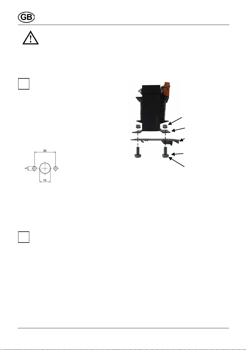
Installation plates for the types TRE1.6 S-2
and TR0.8 S-2 are enclosed for installation
on a support rail TS35. These must be
attached using 2 screws to the foot plate of
the transformer in accordance with the
installation figure below.
(Torque: 2.5Nm).
Startup
Before startup, install all system components
according to their operating instructions.
Verify agreement with the technical data,
see type plate.
Switch on the mains fuse.
Perform a function test in all 5 speed levels.
i
i
Self-locking nut M4
Foot plate transformer
Installation plate
U
-washer M4
Screw M4x10
9

7. Maintenance
Maintenance and care activities may be
performed only by qualified electricians.
Terminals and connections must be regularly
checked for secure contacts and cleaned
from soiling if necessary. The device does not
require any maintenance of properly used.
8. Fault correction
●Consult a qualified electrician with any
fault!
●Repairs must only be carried out by
qualified electricians!
DANGER
Danger to life!
Before opening the switch
cabinet of the 5-stage
transformer, isolate all poles
from the mains (switch off the
mains fuse and put a visible
sign in position prohibiting
switching on).
Fault Measure
Fan does not
start.
Check whether mains fuse
is switched on.
As necessary, switch it on.
Commission a qualified
electrician to check the
device fuse and replace if
necessary.
Only use fuses with
ratings according to the
following specifications.
G-fuse inserts:
– TRE 1.6 S-2: T 2.0/250V
– TRE 3.3 S-2: T 4.0/250V
– TRE 6.5 S-2: T 8.0/250V
– TR 0.8 S-2: T 1.0/500V
– TR 2.5 S-2: T 3.15/500V
– TR 6.6 S-2: T 8.0/500V
9. Disposal
Do not dispose with domestic
waste!
The 5-stage transformer and 5-stage
switch contains some recyclable
materials and some substances that
must not enter domestic waste.
After its service life has expired,
dispose of the 5-stage transformer
and 5-stage switch in accordance with
the applicable regulations in your
country.
i
10

TRE..S-2, TR.. S-2,
ESS 20,DSS 20
1. Volume de livraison
TRE.. S-2 ou TR.. S-2
Transformateur à 5 niveaux TRE.. S-2 ou TR..
S-2 avec équerre de pied et bornes de
raccordement, notice d'utilisation.
ESS 20 ou DSS 20 (Option)
Commutateur à 5 niveaux ESS 20 ou DSS 20
pour transformateur à 5 niveaux, notice
d'utilisation.
2. Symboles utilisés
Symboles d'avertissement
DANGER
Danger de mort !
Le non respect peut entrainer la
mort ou de graves blessures
corporelles.
Autres symboles
Symbole INFO : Ce symbole
informe des passages de textes
délivrant des informations et
conseils importants.
●Symbole de liste :
Liste contenant des informations
importantes sur le sujet
correspondant.
Symbole d'action :
Liste des activités à réaliser.
Réalisez les instructions
indiquées dans l'ordre
d'apparition.
3. Description du produit
Transformateurs à 5 niveaux TRE.. S-2
Transformateur 230-V à 5 tensions de sortie.
Configuration ouverte. Équerre de pied
robuste pour la fixation. En combinaison avec
le commutateur à niveaux pour la commande
de la vitesse de rotation des ventilateurs à
courant alternatif monophasé.
Transformateurs à 5 niveaux TR.. S-2
Transformateur 400-V à 5 tensions de sortie.
Configuration ouverte. Équerre de pied
robuste pour la fixation. En combinaison avec
le commutateur à niveaux pour la commande
de la vitesse de rotation des ventilateurs à
courant continu.
Commutateur à 5 niveaux ESS 20(Option):
En combinaison avec TRE.. Transformateurs
S-2 pour la commande de la vitesse de
rotation des ventilateurs à courant alternatif.
Commutateur à 5 niveaux DSS 20(Option):
En combinaison avec TR.. Transformateurs
S-2 pour la commande de la vitesse de
rotation des ventilateurs à courant continu.
4. Caractéristiques techniques
Transformateur secteur
TRE.. S-2, TR.. S-2
– selon EN 61558 –
●Température ambiante
autorisée max. + 40 °C
●Humidité relative de l'air 55% ... 60%
(à une température ambiante de 20 °C)
●Type de protection : IP 00
Pour plus d'informations, voir l'étiquette
signalétique.
En option : Commutateur à niveau
ESS 20, DSS 20 – selon EN 60947 –
●Tension de mesure max. 400 V
●Fréquence du réseau : 50 Hz ou 60 Hz
●Charge maximale 20 A
●Profondeur de montage ESS 2081 mm
Profondeur de montage DSS 20133 mm
●Température ambiante
autorisée max. + 40 °C
●Type de protection : IP 00
●Capot de recouvrement selon BGV A3
(protection contre le contact)
i
11

Dimensions, poids
L x H x P
[mm]
Poid
s
[kg]
max.
Charge
[A]
TRE1,6 S-2* 84 x 75 x 95 2,2 1,6
TRE 3,3 S-2
105 x 80 x 110
2,9
3,3
TRE 6,5 S-2
120 x 100 x 120
5,5
6,5
TR 0,8 S-2* 84 x 75 x 95 4,1 0,8
TR 2,5 S-2
120 x 90 x 120
8,0
2,5
TR 6,6 S-2
150 x 115 x 155
20,0
6,6
* avec plaque de montage pour installation
sur rail porteur TS35.
5. Instructions fondamentales de
sécurité
Instructions générales de sécurité
●Lire attentivement les instructions de
sécurité avant la mise en service.
●Conserver la notice.
●Le montage, le raccordement électrique et
les réparations sont réservés
exclusivement à des électriciens
spécialisés..
●Raccorder le transformateur à 5 niveaux et
le commutateur à 5 niveaux exclusivement
à une installation électrique fixe !
– Section de câble maximale autorisée
1,5 mm².
– Dispositif de séparation du réseau
d'ouverture de contact d'au moins 3 mm
par pôle nécessaire.
●Exploiter le transformateur à 5 niveaux et le
commutateur à 5 niveaux exclusivement à
la tension et la fréquence indiquées sur les
étiquettes signalétiques.
●Exploiter le transformateur à 5 niveaux et le
commutateur à 5 niveaux uniquement
entièrement montés.
●Les modifications et transformations sur le
transformateur à 5 niveaux et le
commutateur à 5 niveaux ne sont pas
autorisées et déchargent Maico de toute
garantie.
Utilisation conforme à l'usage prévu
●Pour le réglage de la vitesse de rotation (à
5 niveaux).
Selon les configurations d'appareil, pour
les ventilateurs à courant alternatif ou
continu.
●Pour un ou plusieurs ventilateurs de même
tension et fréquence de
fonctionnement. Ne pas dépasser la
charge maximale.
●TRE.. S-2 et TR.. S-2 pour le montage en
armoire électrique.
●ESS 20 et DSS 20 pour la fixation en
façade dans l'armoire électrique.
●Ventilateurs à courant continu en
combinaison avec TR.. Protéger les S-2,
côté construction, contre les surcharges
thermiques ou le fonctionnement biphasé,
par exemple, avec le contacteur moteur
Maico MVS 6.
Mauvaises utilisations prévisibles
Maico ne garantit pas les dommages
consécutifs à une utilisation non conforme.
Ne jamais utiliser le transformateur à 5
niveaux et le commutateur à 5 niveaux :
●à proximité de matériaux, liquides ou gaz
inflammables.
●dans des atmosphères à risque
d'explosion.
Transformateurs à 5 niveaux TR.. Ne jamais
utiliser les S-2 sans contacteur moteur
intégral ni protection contre le fonctionnement
biphasé.
Mentions légales : © Maico Elektroapparate-
Fabrik GmbH. Notice d'origine en allemand.
Sous réserve d'erreurs d'impression,
d'erreurs et de modifications techniques.
12
6. Montage, Raccordement
électrique
DANGER
Danger de mort par choc
électrique !
Couper le fusible réseau avant
tout travail sur le dispositif
électrique !
Apposer un panneau
d'avertissement contre tout
redémarrage intempestif.
Respecter impérativement, pour l
'installation électrique et le montage
de l'appareil, les directives en vigueur,
en Allemagne, en particulier
DIN VDE0100 et les parties
concernées.
Visser le transformateur à 5 niveaux aux
deux équerres de pied avec le coffret
électrique.
Fixer le transformateur à 5 niveaux à
l'avant de l'armoire électrique. Respecter
les dimensions de perçage et les distances
suivantes.
Effectuer le raccordement électrique sur la
borne de raccordement du transformateur
à 5 niveaux suivant le plan de câblage, voir
les schémas de câblage pages 5 .. 7 de
cette notice de montage.
Réaliser, côté construction, la
sécurisation du transformateur à 5
niveaux. Les fusibles de l'appareil
(voir tableau de droite) doivent être
préparés côté construction.
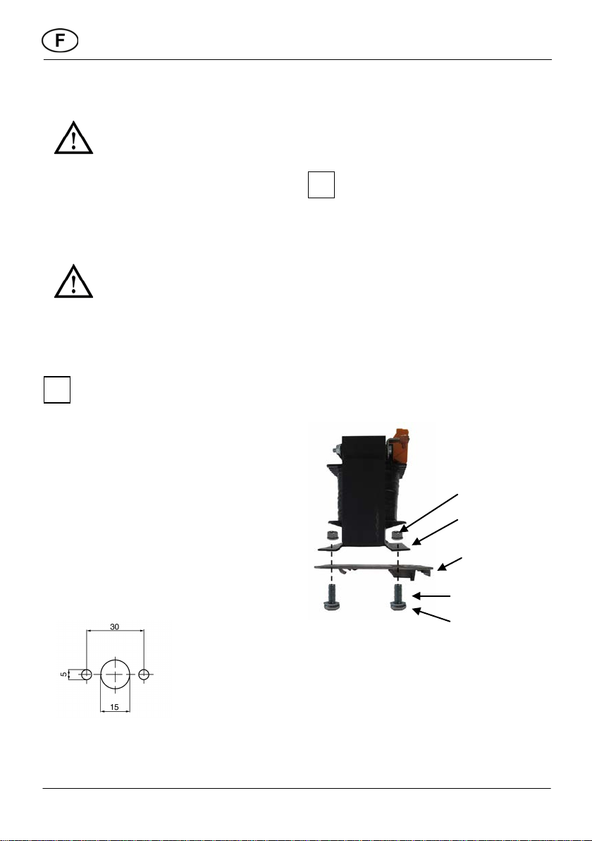
Les types TRE1,6 S-2 et TR0,8 S-2 sont
livrés avec des plaques de montage pour
l'installation sur un rail porteur TS35. Elles
sont à fixer suivant l'illustration de montage
fournie, à l'aide de 2 vis, à la plaque de pied
du transformateur.
(Couple: 2,5Nm).
DANGER
Risque de mort par choc
électrique dû à une fixation
insuffisante du transformateur
à 5 niveaux.
Préparer, côté construction,
du matériel de fixation adapté
!
i
i
Écrou de blocage M4
Plaque de pied
Transformateur
Plaque de montage
Rondelle en U M4
Vis M4x10
13

Mise en service
Installer, avant la mise en service, tous les
composants du système suivant la notice
d'utilisation.
Vérifier la cohérence avec les
caractéristiques techniques, voir l'étiquette
signalétique.
Allumer la protection du réseau.
Effectuer un test de fonctionnement aux 5
niveaux de vitesse de rotation.
7. Entretien
Seuls des électriciens qualifiés sont habilités
à effectuer les travaux de maintenance et
d'entretien.
Vérifier régulièrement le contact des bornes
et liaisons de raccordement et les nettoyer, le
cas échéant, des impuretés. L'appareil ne
nécessite pas de maintenance si on respecte
l'utilisation conforme à l'usage prévu.
8. Dépannage
●Appeler un électricien spécialisé pour
tout défaut !
●Seuls des électriciens qualifiés sont
autorisés à effectuer les réparations !
DANGER
Danger de mort par choc
électrique !
Couper, avant l'ouverture de
l'armoire électrique, tous les
pôles du transformateur à 5
niveaux (couper le fusible
secteur et apposer un
panneau d'interdiction de
remise en service).
Défaut Mesure
Le ventilateur
ne démarre
pas.
Vérifier si la protection
réseau est allumée.
L'allumer, le cas échéant.
Faire vérifier et/ou
remplacer les fusibles de
l'appareil par un
électricien spécialisé.
Utiliser exclusivement des
fusibles suivant les
indications ci-après.
Utilisation de fusibles G :
– TRE 1,6 S-2 : T 2,0/250V
– TRE 3,3 S-2 : T 4,0/250V
– TRE 6,5 S-2 : T 8,0/250V
– TR 0,8 S-2 : T 1,0/500V
– TR 2,5 S-2 : T 3,15/500V
– TR 6,6 S-2 : T 8,0/500V
9. Élimination
Ne pas jeter avec les ordures
ménagères !
Le transformateur à 5 niveaux et le
commutateur à 5 niveaux contiennent
des composants partiellement
recyclables ainsi que des substances
ne devant pas arriver dans les ordures
ménagères.
Éliminez le transformateur à 5 niveaux et le
commutateur à 5 niveaux en fin de vie,
selon les dispositions valables dans votre
pays.
i
14
D
GB
F
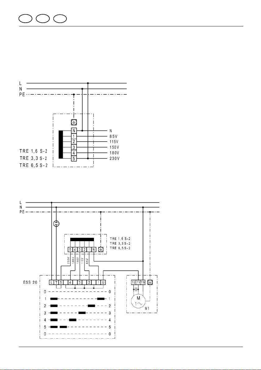
10. Schaltbilder / Wiring diagrams
Schémas de branchement
M1
Ventilator (Kondensatormotor)
Fan (motor capacitor)
Ventilateur (condensateur de moteur)
TRE 1,6 S-2, TRE 3,3 S-2, TRE 6,5 S-2
5
-Stufentransformator; 5 step transformer; Transformateurs à 5 gradins
Wechselstrom 230
V, 50/60 Hz; alternating current 230V, 50/60 Hz; courant alternatif 230V, 50/60 Hz
ESS 20
5
-Stufentransformator; 5 step transformer; Transformateurs à 5 gradins
Wechselstrom 230V, 50/60 Hz; alternating current 230V, 50/60 Hz; courant alternatif 230V, 50/60 Hz
15

D
GB
F
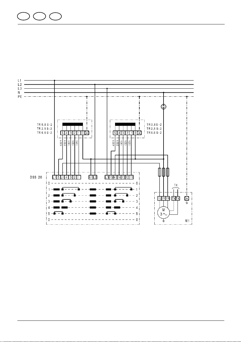
Schaltbilder / Wiring diagrams
Schémas de branchement
TR 0,8 S-2, TR 2,5 S-2, TR 6,6 S-2
5
-Stufentransformator; 5 step transformer; Transformateurs à 5 gradins
Drehstrom 400
V, 50/60 Hz; alternating current 400V, 50/60Hz; courant triphasé 400V, 50/60Hz
16
D
GB
F
Schaltbilder / Wiring diagrams
Schémas de branchement
DSS 20 5-Stufenschalter; Switches for 5 steps; Commutateur à 5-étages
TR.. 5-Stufentransformator; 5 step transformer; Transformateurs à 5 gradins
M1 Ventilator (Drehstrommotor); fan motor (three-phase);
moteur de ventilateur (curant triphasé)
DSS 20
5
-Stufenschalter; Switches for 5 steps; Commutateur à 5-étages
Drehstrom 400
V, 50/60 Hz; alternating current 400V, 50/60Hz; courant triphasé 400V, 50/60Hz
17

18

Notizen:
_______________________________________________________
_______________________________________________________
_______________________________________________________
_______________________________________________________
_______________________________________________________
_______________________________________________________
_______________________________________________________
_______________________________________________________
_______________________________________________________
_______________________________________________________
_______________________________________________________
_______________________________________________________
_______________________________________________________
_______________________________________________________
_______________________________________________________
_______________________________________________________
_______________________________________________________
_______________________________________________________
_______________________________________________________
_______________________________________________________
19

Maico Elektroapparate-Fabrik GmbH • Steinbeisstr. 20 • 78056 Villingen-Schwenningen •
06.14_Wi
20
This manual suits for next models
5
Table of contents
Languages:
Other Maico Transformer manuals


