Kidde Fire Systems KRS-100 Installation guide

KRS-100
Nitrogen
Releasing
System
Application,
Operation and
Maintenance Manual
P/N 83-KRS100-001
September 2002
FM
APPROVED
UL Listing File No.
EX 3559, EX 2153


83-KRS100-001September 2002
KRS-100 Nitrogen Releasing System
Table of Contents
1-1 Scope ........................................................................................................................................ 1
2-1 General Description ................................................................................................................... 1
3-1 Installation ................................................................................................................................. 2
3-1.1 Location ..................................................................................................................................... 2
3-1.1 POA & SVA Mounting ................................................................................................................ 3
3-1.1.1 POA Mounting ........................................................................................................................... 3
3-1.1.2 SVA Mounting ............................................................................................................................ 3
3-1.2 Actuator Valve Asse bly Mounting ...........................................................................................3
3-1.3 Tubing ........................................................................................................................................ 3
3-1.3.1 Tubing and Fittings .................................................................................................................... 3
3-1.4 Control Head Mounting (To Actuator Valve Asse bly) .............................................................. 4
4-1 Syste Check-Out .................................................................................................................... 4
4-1.1 For Control Head Operation ...................................................................................................... 4
5-1 Readying the Syste ................................................................................................................. 4
6-1 Inspection And Maintenance ..................................................................................................... 5
6-1.1 KRS-100 Asse bly Condition.................................................................................................... 5
6-1.2 Nitrogen Cylinder Pressurization ............................................................................................... 5
6-1.3 Detection and Actuation ............................................................................................................. 5
List of Figures
1 KRS-100 Syste Detail w/POA 87-100012-001 ........................................................................ 2
2 KRS-100 Syste Detail w/SVA 87-120042-001 ........................................................................ 2
3 Spacer Detail ............................................................................................................................. 3
List of Tables
1 Tubing Li itations ..................................................................................................................... 3

September 200283-KRS100-001
KRS-100 Nitrogen Releasing System
THIS PAGE INTENTIONALLY LEFT BLANK.

83-KRS100-001September 2002 1
KRS-100 Nitrogen Releasing System
KRS-100 NITROGEN RELEASING SYSTE
Application, Operation, and Maintenance
of KRS-100 Pne matic Releasing Device
1-1 SCOPE
This anual is to be used in conjunction with the UL Listed
and Factory Mutual Approved Kidde Industrial Dry Che i-
cal Instruction Manual (P/N 220423) dated Nove ber 1998,
and the Kidde Wet Che ical Instruction Manual (P/N 87-
122000-001) dated February 1997. All other syste li ita-
tions (control head, detection, anual pull, gas valve, etc.)
ust be in accordance with the respective instruction anu-
als.
2-1 GENERAL DESCRIPTION
The KRS-100 releasing device consists of a nitrogen cylin-
der (P/N 83-100004-001) and actuator valve asse bly (P/
N 83-100010-001). The nitrogen cylinder is pressurized to
1800 psig (70°F).
The function of the KRS-100 releasing device is to provide
a pressure-operated eans for releasing Kidde pre-engi-
neered wet che ical and dry che ical fire-suppression sys-
te s. The KRS-100 utilizes the Kidde pre-engineered
echanical, pneu atic rate of rise, electric, and tande
control heads, any of which can be ounted on the KRS-
100 actuator valve asse bly.The release is acco plished
using KRS-100 cylinder pressure discharged through cop-
per tubing into pressure-operated actuators (P/N 87-
100012-001 or 87-120042-001) located on Kidde
pre-engineered wet or dry che ical syste cylinders. (See
Figure 1 and Figure 2.)
Note: Pressure Operated Actuators (POA) P/N 87-
100012-001 and Syste Valve Actuators (SVA) P/
N 87-120042-001 cannot be ixed on any syste .
Use only one type on a syste .
When pressure fro the KRS-100 cylinder is applied, the
piston in the pressure-operated actuator pushes on the
che ical cylinder valve ste .
The piston re ains in place (extended) until the pressure
in the copper tubing is bled off and the pressure in each
pressure-operated actuator is released. Pushing down on
the valve core of the pressure-operated actuator releases
this pressure.
Note: Pressure in the pressure-operated actuator ust
be released before re oving the actuator fro the
agent storage cylinder. (See Figure 1.)
In addition to the pressure-operated actuator, the KRS-100
can also be used to operate pressure-operated switches
(P/Ns 486536 and 486536-010).
A ini u of two and axi u of ten agent storage cyl-
inders can be operated fro one KRS-100. Up to 3 pres-
sure-operated switches can be installed on the KRS-100
actuation line.
Multiple KRS-100 releasing units ay be used when the
nu ber of agent storage cylinders exceeds the axi u
capacity of one KRS-100 releasing unit. The KRS-100 sys-
te is fully odular and is expandable to fit any size appli-
cation.
Two or ore KRS-100 cylinders ay be used when utiliz-
ing two or ore different types of detection to cover the
sa e hazard. An exa ple would be the use of a co -
bination of pneu atic rate-of-rise and fixed-te perature
electric detection in a hazard. In this exa ple a pneu atic
rate of rise control head would be used on one KRS cylin-
der and an electric control head on the other. Operation of
either detection syste would release the extinguishing
syste by eans of the KRS-100 releasing device to which
it is connected. Refer to proper Kidde Instruction Manual
listed in the scope of this addendu (Paragraph 1) for pneu-
atic detection, pneu atic control head, electric detection
and electric control-head installation details. If using a Kidde
control panel refer to the Installation Manual for the control
panel for detection and control installation details.
There are nu erous applications where the use of the KRS-
100 si plifies the overall installation of an extinguishing
syste . It is often ore convenient and econo ical to in-
stall the extinguishing syste cylinders so that each is in
close proxi ity to the space it protects rather than having
all cylinders ounted together in a bank. Piping is thus kept
to a ini u . Such an arrange ent is conveniently i ple-
ented by the KRS-100.
Other applications include those where the hazard area is
unsuitable for standard control heads. Here we can use
the KRS-100 cylinder installed outside the unsuitable area
with the actuation tubing run to the extinguishing syste
cylinders located within the area.
The KRS-100 is ideally suited to a hazard consisting of
kitchen range hoods on two or ore floors, connected to a
co on exhaust duct. For this type of hazard each kitchen
hood would be protected with an independent wet or dry
che ical syste . The detection for each hood, however,
would be connected to a KRS-100 cylinder on its floor rather
than to the wet or dry che ical syste .
The KRS-100s on the various floors would be connected
to each other and to each wet or dry che ical syste . A
fire at any hood would thus release all of the syste s. In
this way the entire hazard consisting of all the hoods and
the co on duct would be protected as required without
the necessity of a co plicated co on detection syste ,

September 200283-KRS100-001 2
KRS-100 Nitrogen Releasing System
and without having to use a single extinguishing syste
which could be difficult to install within its piping li itations.
Whenever two or ore KRS cylinders are used, each ust
be isolated fro the others by a check valve (P/N 259404).
The purpose of the check valves is to prevent loss of pres-
sure during discharge on one cylinder in the event that one
of the cylinders is disconnected.
2069
N
L
PSI 0
kPa 0
I
W
U
E
S
M
A
C
M
I
H
T
C
W
E
T
E
H
SSTELEMENT
06-118031-001
L
O
1207
RECHARGE
175
OVERCHARGED
300
Y
06-118031-001
H
E
W
I
T
kPa 0
PSI 0
M
S
U
N
C
I
M
C
E
H
E
T
W
O
A
L
OVERCHARGED
SSTELEMENT
2069
L
Y
300
1207
175
RECHARGE
MOUNTING KIT
APPROX. 2 1/2 INCHES IN DIA.
WET OR DRY CHEMICAL
SYSTEM CYLINDER
KRS-100 ACTUATOR
VALVE ASSEMBLY
P/N 83-100010-001
KRS-100 (NITROGEN)
P/N 83-100004-001
PRESSURE OPERATED
ACTUATOR
P/N 87-100012-001
VALVE CORE
VENT CHECK
P/N WK-877810-000
(OPTIONAL)
P/N 06-129706-001
100 FT. MAX.- 1/4 INCH COPPER TUBING
(3) THREE PRESSURE SWITCHES AND
(10) TEN CYLINDERS
50 FT. MAX.
1/4 INCH COPPER TUBING
OUTLET
CYLINDER
Figure 1. KRS-100 Syste Detail w/POA 87-100012-001
WET OR DRY CHEMICAL
SYSTEM CYLINDER
SYSTEM VALVE
ACTUATOR
P/N 87-120042-001
APPROX. 2 1/2 INCHES IN DIA.
VENT CHECK
P/N WK-877810-000
(OPTIONAL) OR
ADDITIONAL CYLS.
MOUNTING KIT
KRS-100 ACTUATOR
VALVE ASSEMBLY
KRS-100 (NITROGEN)
P/N 83-100004-001
P/N 06-129706-001
CYLINDER
OUTLET
P/N 83-100010-001
100 FT. MAX.- 1/4 INCH COPPER TUBING
(3) THREE PRESSURE SWITCHES AND
(10) TEN CYLINDERS
50 FT. MAX.
1/4 INCH COPPER TUBING
Figure 2. KRS-100 Syste Detail w/SVA 87-120042-001
3-1 INSTALLATION
3-1.1 Locatio
The KRS-100 cylinder and actuator valve asse bly shall
be located where the te perature is between -40°F (-40°C)
and 120°F (48.9°C). The entire asse bly, cylinder, actua-
tor, and control head ust be protected fro rain, snow, or
other incle ent weather conditions by a suitable total or
partial enclosure. They all ust be ounted in such a way
that no part of the asse bly stands in water or other liquid.

83-KRS100-001September 2002 3
KRS-100 Nitrogen Releasing System
The KRS-100 releasing device ay be ounted either verti-
cally (plu b) with the control head or actuator at the top, or
horizontally (level), or at any angle between vertical and
horizontal.
3-1.1 POA & SVA Mou ti g
Prior to ounting the actuator (POA P/N 87-100012-001 or
SVA 87-120042-001) to the wet or dry che ical cylinder
valve, ake certain the actuator piston is flush with the
botto of the actuator body. If the piston is not flush, per-
for the following procedure.
3-1.1.1 POA MOUNTING
Place the unit on a flat surface and depress the valve core
while pushing down on the asse bly. This will push the
piston into the body of the actuator.
3-1.1.2 SVA MOUNTING
Push the spring loaded plunger in and push in the piston.
3-1.2 Actuator Valve Assembly Mou ti g
The actuator valve asse bly (P/N 83-100010-001) can be
ounted using the bolt holes located on the side flange of
the actuator valve body. The total asse bly should be se-
cured to a surface which will support at least three ti es
the total asse bly dead weight. Use both ounting holes
to secure the asse bly.
For applications where space is tight and clearance is needed
between the control head and the wall, use a spacer (P/N 83-
100011-001) to provide the clearance. See Figure 3.
3-1.3 Tubi g
Connect actuation tubing to the outlet on the KRS-100 ac-
tuator valve body. Rea and thoroughly clean all chips and
cutting oil fro the inside of tubing prior to connection. All
tubing is to be securely supported, no ore than ten feet
on centers. (See Table 1 for tubing li itations.)
Table 1. Tubing Li itations
.xaM.niM
metsySlatoT .tf051.tf5
lortnoCneewteB
tsriFdnadaeH
rednilyC
.tf05.tf3
tsriFneewteB
rednilyCtsaLdna .tf001.tf2
3-1.3.1 TUBING AND FITTINGS
The KRS-100 syste uses 1/4-inch O.D. copper tubing
(0.030-inch ini u wall) with flared or high-co pression
tubing fittings. Tubing is also known as soft copper refrig-
eration/AC tubing. Flared fittings are SAE 45° flared brass
tube. Co pression fittings are high-pressure brass tube.
The copper tubing should be cut squarely with a tubing cutter
and carefully rea ed to re ove all burrs before flaring with
a standard flaring tool or applying co pression fittings. The
tubing need not be enclosed in conduit except where it would
otherwise be exposed within seven feet of the floor, or where
it is subject to cutting or crushing. There is no li it on bends,
SERVICING THE SYSTEM
INSTALLING, INSPECTING OR
REMOVE SAFETY PIN AFTER
CAUTION
SAFETY PIN
2.50
0.312-18 UNC
0.875
2.25
0.625
3.50
5.25
0.406 DIA. HOLE
0.375 CLEAR HOLE
1.375
#7 GA.
2.50
SPACER
P/N 83-100011-001
MOUNTING
FLANGE
Figure 3. Spacer Detail

September 200283-KRS100-001 4
KRS-100 Nitrogen Releasing System
but bends ust be ade so that the tubing will not flatten
or kink. A single coil of tubing approxi ately 2-1/2 inches in
dia eter is desirable at each flare or co pression fitting.
The coil ay be neatly ade by wrapping the tubing around
any convenient cylindrical object of that dia eter.
When sliding the tubing through conduit the leading end of
the tube should first be cri ped and bent double so as to
provide a s ooth sliding surface and to prevent possible
foreign atter in the conduit fro entering the tubing. All
tubing fittings with pipe threads, as at the KRS-100 actua-
tor valve body, the pressure-operated actuator and other
accessory devices, shall be asse bled with Teflon tape
wrapped around the ale pipe threads.
All tubing should be blown out with air or nitrogen prior to
aking final connections. Table 1 su arizes the length
of tubing allowed per each KRS-100 cylinder.
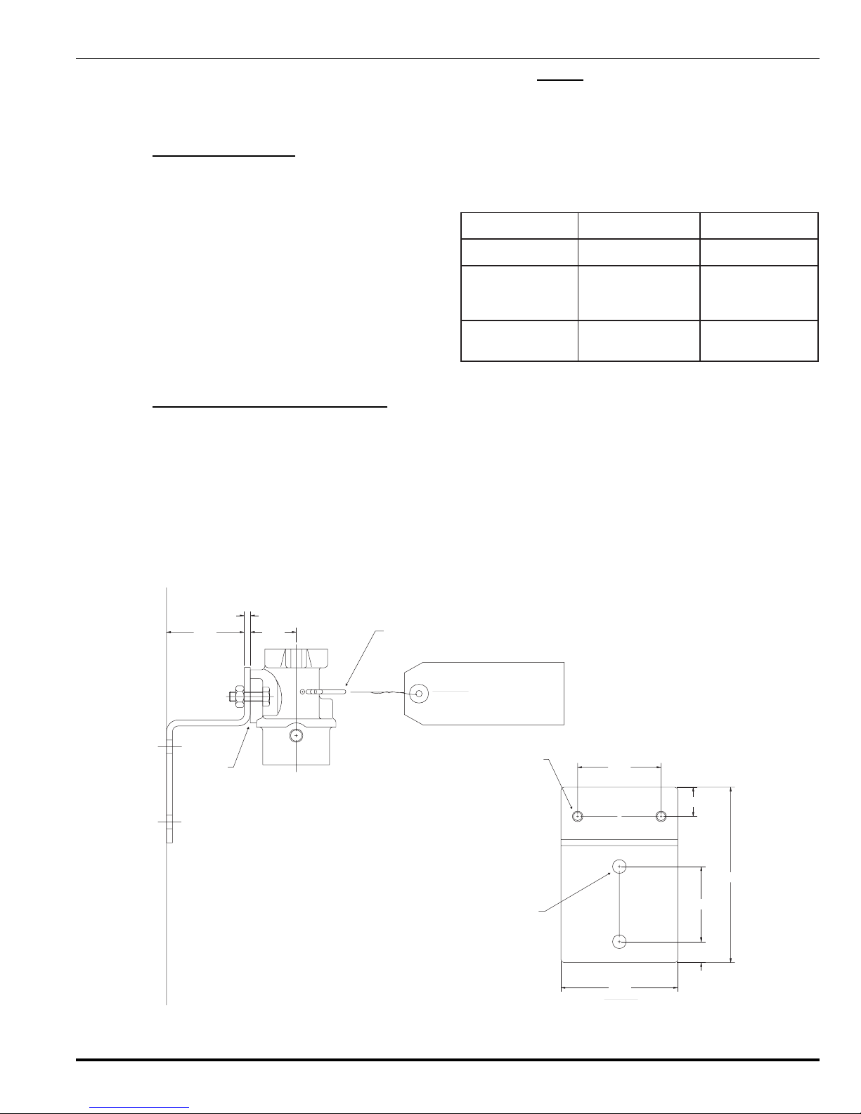
3-1.4 Co trol Head Mou ti g
(To Actuator Valve Assembly)
Note: The syste control head ust be ounted to the
KRS-100 actuator valve body using the ounting kit
(P/N 06-129706-001) supplied with the Actuator Valve
Asse bly (P/N 83-100010-001).
This kit contains a rubber gasket that ust be placed be-
tween the ating surfaces of the actuator body and the
control head housing. This kit also contains Teflon coated
bolts and nylon washers for fastening the actuator valve
asse bly to the control head housing.
Prior to ounting a control head on the KRS-100 actuator
valve asse bly ake certain of the following:
1. The control head is in the SET position. On echani-
cal installations the anual release lever should be
pushed up and the tensioning tool inserted in safety
hole in the housing. On electrical installations ake
certain the solenoid trigger holds the actuating lever.
The actuating ca arrow should be pointed away fro
the ratchet spool, (toward the SET position on face-
plate), and the release plunger should be flush or slightly
retracted within the control head body.
2. Ensure the safety pin is in place on the actuator valve
asse bly. See Figure 2.
3. Do not install the nitrogen cartridge at this ti e.
Note: Control Heads are shipped in the SET position with
cover off for ease of installation. There are
tensioning tools shipped with the echanical and
tande control heads to enable proper tension
setting on the cable. A tensioning tool ay be used
with the pneu atic control heads. There is no
tensioning tool per itted with the electrical control
heads. The plunger of the electric solenoid holds
the control head echanis in proper position for
the SET position.
4-1 SYSTEM CHECK-OUT
To de onstrate proper operation of the actuating syste
the following check-out is to be acco plished prior to i -
stalli g the itroge cyli der (P/N 83-100004-001).
4-1.1 For Co trol Head Operatio
1. Re ove the tensioning tool (when used) fro the safety
hole in the control head. If the syste is properly in-
stalled, the head should re ain in the SET position,
fully prepared for either auto atic or anual opera-
tion.
2. Re ove safety pin fro actuator valve asse bly.
3. All cables, with the exception of re ote pull cables,
should be in a taut condition if properly installed.
4. For fusible link check-out, cut the S hook farthest fro
the control head (ter inal link). The released tension
should per it the control head to operate, triggering
the releasing echanis .
5. Check to see that the actuating ca is in the operated
position and that the actuating ca (shaft arrow) has
rotated to the released position. All cables should be
slack, including re ote cable.
6. To check out electrical control heads, do the following:
Ensure that the actuating ca (shaft arrow) is turned
to the SET position. Energize the control head by ap-
plying heat directly to the ther ostats or operating the
panel.
7. Check that the control head triggering echanis has
released. Check that the actuating ca arrow has ro-
tated to the release position.
8. Check to see that the gas valve and/or electric shut-off
have operated. Slack in the cable is an indication, but
only the shut-off of gas and/or shut-off of electric cur-
rent to the hazard de onstrates that these units have
properly functioned.
9. Inspect all other aspects of syste operation, such as
da pers and door holders to see that the syste has
been installed properly.
10. After resetting the syste as outlined below, repeat
check-out by operating local and re ote anual con-
trols to assure their operation.
5-1 READYING THE SYSTEM
If all conditions have proven to be operational, place sys-
te in operation as follows:
1. If the fusible link syste is used, install a new S hook
in the detection line. If the electric syste is used, re-
place ents should not be required.
2. Reset the control head.
3. Re ove the control head tensioning tool when done,
and discard. Electric control heads do ot use
tensioning tools.

83-KRS100-001September 2002 5
KRS-100 Nitrogen Releasing System
4. Install control head cover aking sure notch in anual
lever goes over anual release lever asse bly. Se-
cure with five screws supplied.
5. Ensure that safety pin is in place on the actuator valve
asse bly. If the pin cannot be placed in the actuator,
verify that control head is SET. See Figure 2.
6. Re ove and discard tensioning tools in gas valve and/
or electric shut-off and secure covers to units.
7. Turn on electric power and open ain gas line shut-off
valve. Ensure that pilot lights are lit.
8. Reset any electrical shutdown equip ent operated by
the switch contacts.
9. Reset any da pers or other auxiliary equip ent.
10. Install nitrogen cartridge by co pletely threading the
cartridge into the actuator asse bly.
11. Re ove the pin fro the actuator valve asse bly and
discard.
The KRS-100 syste is now in the ready position.
6-1 INSPECTION AND MAINTENANCE
Inspect se i-annually or ore frequently. Inspections
should be done by a qualified Kidde distributor.
Particular attention should be given to:
KRS-100 Assembly Co ditio .
Nitroge Cyli der Pressurizatio : Ensure that it is
at proper weight.
Note: Nitrogen cylinder full weight includes the shipping
cap, ensure that it is installed prior to weighing.
Detectio a d Actuatio System.
Actuatio Tubi g.
Auxiliary Equipme t.
6-1.1 KRS-100 Assembly Co ditio
The actuator valve asse bly ust be inspected internally
for nicks, dents, and scratches which would cause pos-
sible failure. Check to see that no part of the nitrogen cylin-
der is da aged or corroded.
6-1.2 Nitroge Cyli der Pressurizatio
Re ove the nitrogen cylinder and install shipping cap.
Weigh cylinder. Full cylinder weight is arked on the label.
If cylinder weight loss exceeds 3.5 gra s, the cylinder (P/
N 83-100004-001) ust be replaced.
When replacing a cylinder, the gasket located in the actua-
tor (P/N WF-263413-000) ust also be replaced.
6-1.3 Detectio a d Actuatio
The detectors should be checked (and cleaned if neces-
sary) to assure that they are free of foreign substances. If
the detection syste is supervised, the supervisory fea-
tures should be checked to deter ine that the detection
syste is in satisfactory condition. The ethods and pro-
cedures for this inspection should be in accordance with
anufacturers reco endations.

September 200283-KRS100-001 6
KRS-100 Nitrogen Releasing System
(THIS PAGE INTENTIONALLY LEFT BLANK)


06-235864-001 Rev. AB ©2002 Kidde-Fenwal, Inc. Printed in SA
LIMITED WARRANTY STATEMENT
Kidde-Fenwal, Inc. represents that this product is free from defects in material and workmanship, and it will repair or replace
any product or part thereof which proves to be defective in workmanship or material for a period of twelve (12 months from
the date of purchase but not to exceed eighteen (18 months after shipment by Kidde-Fenwal Inc. For a full description of
Kidde-Fenwals LIMITED WARRANTY, which, among other things, EXCLUDES warranties of MERCHANTABILITY and
FITNESS FOR A PARTICULAR PURPOSE and liability for CONSEQUENTIAL DAMAGES, please read the entire LIMITED
WARRANTY on the Kidde-Fenwal Quotation, Acceptance of Order and/or Original Invoice which will become part of your
sales agreement. Please contact Kidde-Fenwal directly for a return material authorization (RMA number before returning
material to the factory at Ashland, Massachusetts, shipment prepaid. Kidde-Fenwal will repair or replace and ship prepaid.
These instructions do not purport to cover all the details or variations in the equipment
described, nor do they provide for every possible contingency to be met in connection
with installation, operation and maintenance. All specifications subject to change without
notice. Should further information be desired or should particular problems arise which
are not covered sufficiently for the purchasers purposes, the matter should be referred
to K DDE-FENWAL NC., Ashland, Masssachusetts
Kidde is a registered trademark of Kidde-Fenwal Inc.
Table of contents
Other Kidde Fire Systems Fire Extinguisher manuals