manuals.online logo
Brands
  1. Home
  2. •
  3. Brands
  4. •
  5. Kidde
  6. •
  7. Smoke Alarm
  8. •
  9. Kidde V-PS Assembly instructions

Kidde V-PS Assembly instructions

P/N 3101070-EN • REV 05 • ISS 24FEB16 1 / 2
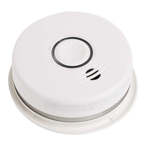
V-PS Photoelectric Smoke
Detector Installation Sheet
Description
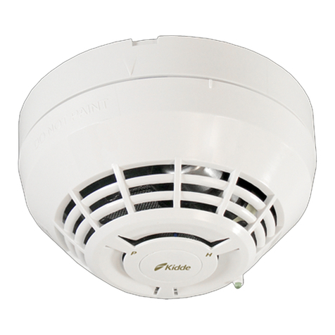
The V-PS Photoelectric Smoke Detector uses an optical sensing
chamber to detect smoke. The detector analyzes the sensor data to
determine when an alarm should be initiated.
The detector continuously monitors changes in sensitivity due to the
environment (e.g., dirt, smoke, temperature, humidity) and notifies the
loop controller of its condition. The detector issues a dirty-sensor
warning when it reaches its preset limit. This notifies the operator of
the need for service while the detector is still operating. The detector is
capable of performing comprehensive self-diagnostics and storing the
results.
LEDs: The V-PS detector uses a bicolor LED to show its status.
• Normal: Green LED flashes
• Alarm: Red LED flashes
Electronic addressing
The control panel automatically assigns addresses to the detectors.
Use a laptop computer to set custom addresses for the detectors. No
addressing switches are used.
Installation
Install and wire this device in accordance with applicable national and
local codes, ordinances, and regulations.
Refer to Vigilant Detector Application Bulletin (P/N 3101109-EN) for
additional information on detector placement and spacing.
WARNINGS
• Risk of system failure. This detector does not operate without
electrical power. As fires frequently cause power interruption,
discuss further safeguards with your local fire protection specialist.
• Risk of system failure. This detector does not sense fires in areas
where smoke cannot reach the detector. Smoke from fires in walls,
roofs, or on the opposite side of closed doors may not reach the
detector.
Notes
• Photoelectric detectors have a wide range of sensing capabilities,
but are best suited for detecting slow, smoldering fires.
• Do not use a detector guard with this detector unless the
combination has been evaluated and found suitable.
• To ensure proper operation, schedule maintenance (regular or
selected) in accordance with the requirements of the authority
having jurisdiction. Refer to NFPA 72 and CAN/ULC-S536.
• To ensure proper operation, store the detector within the
recommended temperature ranges. Allow the detector to stabilize
to room temperature before applying power.
• Keep the dust cover (supplied) on the detector during installation
and remove it prior to commissioning and service. The dust cover
is not a substitute for removing the detector during new
construction or heavy remodeling.
To install the detector:
1. Install and wire the detector base using the installation sheet
supplied with the detector base.
2. Connect the detector to the base by rotating the detector clockwise
until it snaps into the locked position. To remove the head turn it
counterclockwise.
3. If the head must lock to the base, break away the locking tab using
a pair of pliers. See Figure 1.
To remove the detector head after breaking away the locking tab,
insert a small screwdriver into the slot on the side of the base and
press in while simultaneously turning the detector head
counterclockwise.
4. Remove the serial number label from the detector and attach it to
the project documentation.
Figure 1: Locking tab
(1) Locking tab
Maintenance
When cleaning is necessary, the sensing chamber of the detector
easily unsnaps for field cleaning and service.
For warranty and return, see “Contact information” on page 2.
To clean the detector:
1. Remove the detector from the base.
2. Insert a screwdriver in the small slot where the detector cap
connects to the detector body. See Figure 2.
3. Pry the detector cap off the detector body.
4. Squeeze the optical block chamber where the two arrows point,
labeled “squeeze here.”
5. Pull off the optical block chamber.
6. Blow off the optical block base in the detector body using clean
compressed air.
(1)
2 / 2 P/N 3101070-EN • REV 05 • ISS 24FEB16
7. Snap a new optical block chamber in place. Make sure you line up
the two arrows on the block chamber with the snaps on the optical
block base.
8. Connect the detector cap to the detector body by rotating the cap
clockwise until it snaps into a locked position.
9. Install the detector onto the base.
Note: To verify the effectiveness of the cleaning, recalibrate the
device and run a device maintenance report. Refer to the control
panel technical reference manual.
10. Test the detector and verify sensitivity.
Figure 2: Detector disassembly
(1) Slot to insert screwdriver
(2) Optical block chamber
(3) Optical block base
(4) Detector body
(5) Detector cap
Testing
NFPA 72 and CAN/ULC-S537 require a calibrated sensitivity test upon
installation and following any modifications or additions to the system.
The detector can perform this test and generate a system sensitivity
report.
To test the detector:
1. Before initial testing, remove the dust cover from the detector and
notify the proper authorities that the fire alarm system is
undergoing maintenance and will be temporarily out of service.
2. Test the detector using Smoke-In-A-Can (model SM-200) canned
smoke. Carefully follow directions on the can to avoid damage to
the detector.
Specifications
Communication line
voltage
20 Vp-p max.
Current
Normal operating
Alarm
45 µA
45 µA
Smoke sensitivity
UL
ULC
0.67 to 3.66 %/ft. obscuration
0.74 to 3.70 %/ft. obscuration
Environmental
compensation
Automatic
Distance from ceiling
(wall mounted)
12 in. (305 mm) max.
Compatible bases
Standard
Relay
Isolator
Audible
B4U, B4U-LP
RB4U
IB4U
SB4U, SB4U-LF
Operating environment
Temperature
Relative humidity
32 to 120°F (0 to 49°C)
0 to 93% noncondensing
Storage temperature −4 to 140°F (−20 to 60°C)
Regulatory information
North American
standards
Meets: CAN/ULC-S529, UL 268
Follow: CAN/ULC-S524, CAN/ULC-S537,
National Building Code of Canada, National Fire
Code of Canada, and NFPA 72
FCC compliance This device complies with part 15 of the FCC
Rules. Operation is subject to the following two
conditions: (1) This device may not cause harmful
interference, and (2) this device must accept any
interference received, including interference that
may cause undesired operation.
Industry Canada
compliance
This Class A digital apparatus complies with
Canadian ICES-003.
Contact information
For contact information, see www.kiddelifesafety.com.
© 2016 Walter Kidde Portable Equipment, Inc.
All rights reserved.
(1)
(2)
(5)
XXXXXXXX
(3)
(4)

Other Kidde Smoke Alarm manuals

Kidde 910 User manual

Kidde

Kidde 910 User manual

Kidde P9050 User manual

Kidde

Kidde P9050 User manual

Kidde 1296 User manual

Kidde

Kidde 1296 User manual

Kidde P4010ACSAQ-WF User manual

Kidde

Kidde P4010ACSAQ-WF User manual

Kidde HD135F User manual

Kidde

Kidde HD135F User manual

Kidde i9010 User manual

Kidde

Kidde i9010 User manual

Kidde 0916E User manual

Kidde

Kidde 0916E User manual

Kidde 29D User manual

Kidde

Kidde 29D User manual

Kidde 976 User manual

Kidde

Kidde 976 User manual

Kidde 914 User manual

Kidde

Kidde 914 User manual

Kidde KI-PCD Assembly instructions

Kidde

Kidde KI-PCD Assembly instructions

Kidde FIRE SENTRY 0914 User manual

Kidde

Kidde FIRE SENTRY 0914 User manual

Kidde 1235E Guide

Kidde

Kidde 1235E Guide

Kidde 123I Assembly instructions

Kidde

Kidde 123I Assembly instructions

Kidde KN-COB-DP2 User manual

Kidde

Kidde KN-COB-DP2 User manual

Kidde GSA-PS Assembly instructions

Kidde

Kidde GSA-PS Assembly instructions

Kidde i12060A User manual

Kidde

Kidde i12060A User manual

Kidde SL177i User manual

Kidde

Kidde SL177i User manual

Kidde FIRE SENTRY 0914 User manual

Kidde

Kidde FIRE SENTRY 0914 User manual

Kidde P1235CA User manual

Kidde

Kidde P1235CA User manual

Kidde PE910 User manual

Kidde

Kidde PE910 User manual

Kidde KN-COSM-B User manual

Kidde

Kidde KN-COSM-B User manual

Kidde 123I User manual

Kidde

Kidde 123I User manual

Kidde TRUSENSE SMOKE User manual

Kidde

Kidde TRUSENSE SMOKE User manual

Popular Smoke Alarm manuals by other brands

BRK electronic 7030BSLA quick start guide

BRK electronic

BRK electronic 7030BSLA quick start guide

MGC MIX-4010 Installation and maintenance instructions

MGC

MGC MIX-4010 Installation and maintenance instructions

First Alert SA511 user manual

First Alert

First Alert SA511 user manual

ELRO FS811016 instruction manual

ELRO

ELRO FS811016 instruction manual

UniPOS RI31 instruction manual

UniPOS

UniPOS RI31 instruction manual

Bellman & Symfon BE1289 manual

Bellman & Symfon

Bellman & Symfon BE1289 manual

CALECTRO UNIGUARD SUPERFLOW UG-3-NS-AOS quick start guide

CALECTRO

CALECTRO UNIGUARD SUPERFLOW UG-3-NS-AOS quick start guide

SILENT KNIGHT 5700 Installation and operation manual

SILENT KNIGHT

SILENT KNIGHT 5700 Installation and operation manual

Smartwares FSM-123 manual

Smartwares

Smartwares FSM-123 manual

Gemini 501-B user guide

Gemini

Gemini 501-B user guide

Geofire Agrippa User instructions

Geofire

Geofire Agrippa User instructions

First Alert SA320 user manual

First Alert

First Alert SA320 user manual

Fireray 2000 Manual guide

Fireray

Fireray 2000 Manual guide

Vemmio SS-100 quick start guide

Vemmio

Vemmio SS-100 quick start guide

U-Prox Smoke quick start guide

U-Prox

U-Prox Smoke quick start guide

Pro-tec CIRRUS HYBRID Installation and commissioning manual

Pro-tec

Pro-tec CIRRUS HYBRID Installation and commissioning manual

Cavius 2203-002 user manual

Cavius

Cavius 2203-002 user manual

Edwards Signaling SuperDuct ESD-2W manual

Edwards Signaling

Edwards Signaling SuperDuct ESD-2W manual

manuals.online logo
manuals.online logoBrands
  • About & Mission
  • Contact us
  • Privacy Policy
  • Terms and Conditions

Copyright 2025 Manuals.Online. All Rights Reserved.