5
DG Operating Instructions
1 For Your Own Safety
1 For Your Own Safety
1.1 Intended Application
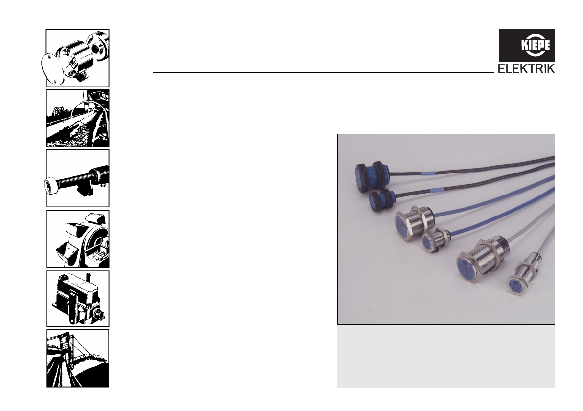
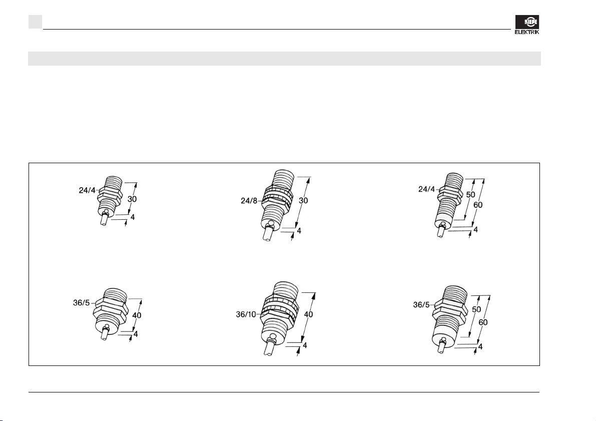
The pulse generators of the DG type series generate
pulses, the frequencies of which depend on the rotation-
al speed. The pulse generators are particularly suited for
application if high accuracy of operation, long service life
as well as wear and corrosion resistance are important.
The pulse generators meet the high requirements of the
relevant regulations.The device is intended for use in
stationary installations and in vehicles.
Applications other than specified and unauthorized mod-
ifications to the device or its components can lead to in-
jury to persons and damage to the device, for which the
manufacturer is not liable.
Make sure that the intended use is not impaired in any
way, even after unexpected outside influence on the de-
vice.
"Intended application" particularly means that any work
performed with or on the device is to be carried out in
accordance with these operating instructions. Only
skilled persons who are familiar with the Regulations
on the Prevention of Accidents as well as the other
generally accepted safety rules are allowed to work on
this device.
You protect yourself and prevent damage to the de-
vice when you apply the device as intended!
1.2 Symbols
Please pay particular attention to the text passages that
are marked with the following symbols:
Danger!
Information that has to be observed at all
events in order to protect the user from being
injured.
Attention!
Information that has to be observed in order
to prevent damage to the device.
Helpful additional information