SPECIFICATIONS
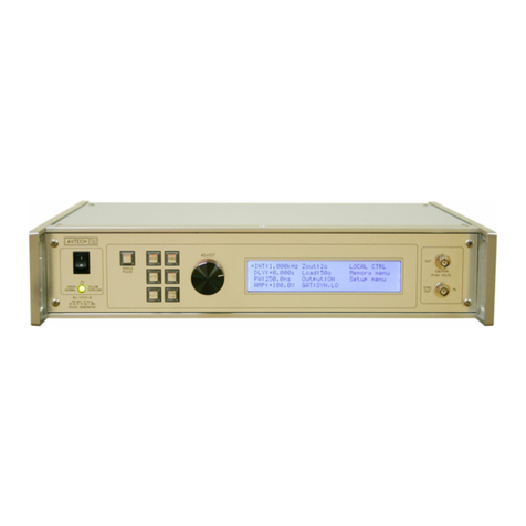
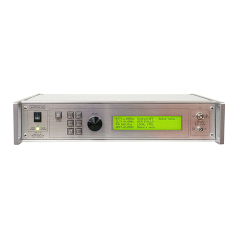
Model AVP-AV-1S-C1
Maximum amplitude2< 1 to 5 V
Pulse width (FWHM) 0.2 - 4 ns
PRF 100 Hz to 1 MHz
Rise time (20%-80%) ≤ 80 ps
Fall time (80%-20%) ≤ 200 ps
Polarity Specify -P, -N, -PN
Required load impedance 50 Ohms5
Accuracy / calibration Not calibrated. At lower pulse widths and higher PRFs, the amplitude tends to
roll off relative to the set value. For high-accuracy applications requiring
traceable calibration, verify the output with a calibrated oscilloscope.
Propagation delay ≤ 200 ns (Ext trig in to pulse out)
Jitter, Ext trig in to pulse out ± 35ps ± 0.015% of sync delay
Trigger modes Internal trigger, or external trigger (TTL level pulse, > 50 ns, 1 kΩ input impedance)
Variable delay Sync to main out 0 to 200 ns, for internal trigger mode only.
No variable delay in external trigger mode
Sync output +3 Volts, > 50 ns, will drive 50 Ohm loads
DC offset or bias insertion Optional3. Apply required DC offset or bias in the range of ± 50V (250 mA max)
to back panel solder terminal.
Monitor output option4Provides a 20 dB (x10) attenuated coincident replica of main output
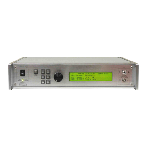
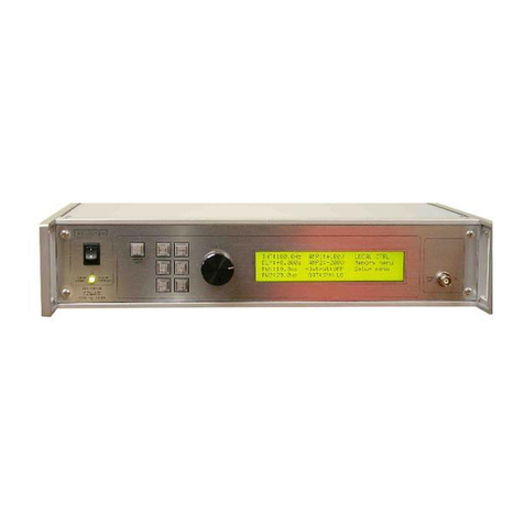
Connectors Out, Monitor SMA. TRIG, SYNC, GATE (-B only) BNC
Optional accessory kit
(attenuators and terminators)
Add the suffix "-AK1" to the model number to include the recommended accessory kit. Consists of
three SMA, 18 GHz, 2 Watt attenuators (10, 20 & 30 dB) for use on the output, and two 50 Ohm,
1 GHz, 1 Watt feed-through terminators (one SMA, one BNC) for use on external trigger inputs.
Optional accessory kit
(coaxial cables and adapters)
Add the suffix "-AK8" to the model number to include the recommended accessory kit.
Consists of one 12-inch SMA-M/SMA-M PE-SR405FL coaxial cable, one 12-inch SMA-M/SMA-M RG-
316 coaxial cable, one 36-inch SMA-M/SMA-M RG-316 coaxial cable, one 24-inch SMA-M/BNC-M RG-
316 coaxial cable, one 36-inch BNC-M/BNC-M RG58C/U coaxial cable, one SMA-F to BNC-M adapter,
one SMA-M to BNC-F adapter, one SMA-F to SMA-F adapter, and one SMA-F to solder cup adapter
Temperature range +5°C to +40°C
Power requirements 100 - 240 Volts, 50 - 60 Hz
Dimensions 100 × 430 × 375 mm (3.9” × 17” × 14.8”)
Chassis material Aluminum, with vinyl trim
1. -C suffix indicates stand-alone lab instrument with internal clock and line powering. No suffix indicates miniature module requiring DC power and external
trigger. (See http //www.avtechpulse.com/formats for details of the four basic instrument formats).
2. For operation at amplitudes of less than 20% of full-scale, best results will be obtained by setting the amplitude near full-scale and using external
attenuators on the output.
3. For externally applied DC offset option suffix model number with -OS. The Avtech AVX-T bias tee can also be used to obtain DC offset. For internally
generated DC offset option (0 to ±5V) add the suffix -OT to the model number.
4. For monitor option add suffix -M.
5. A 50 Ohm load is required. Other loads may damage the instrument. Consult Avtech (info@avtechpulse.com) if you need to drive other load impedances.
