7
Operating Instructions SEG
1 Safety
1 Safety
1.1 Intended use
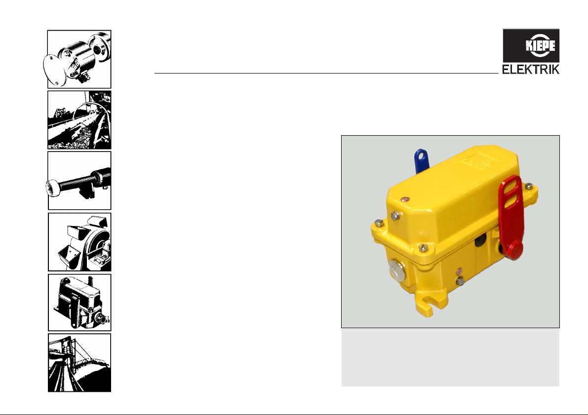
Pull-rope emergency stop switches, type SEG are used
as emergency stop devices actuated on both sides in
stationary conveyor systems in control circuits in accor-
dance with the safety requirements of DIN EN 620 and in
harmony with DIN EN ISO 13850. According to the BGIA
report 2/2008 "Functional safety of machine controls -
application of DIN EN ISO 13849" issued by the German
Social Accident Insurance (Deutsche Gesetzliche Unfall-
versicherung), the pull-rope emergency stop switches
can be used as emergency stop devices in safety control
circuits up to performance level PLe.
These operating instructions describe the intended use,
mechanical mounting/dismounting at the attachment
points for the pull-rope emergency stop switch SEG,
electrical connection and maintenance, repair, commis-
sioning and troubleshooting for the pull-rope emergency
stop switch SEG. These operating instructions do not
contain any information regarding the use and handling
of the pull-rope system or the control.
Improper use of the device and unauthorized changes to
the device and its components may result in injury and/or
damage, for which the manufacturer will not assume
any liability. Ensure that intended use cannot be im-
paired in any way, even by an unforeseen external influ-
ence on the device.
Die vorliegende Dokumentation ist als Teil des Produk-
tes zu betrachten und muss während der Lebensdauer
des Produktes behalten werden und dem jeweiligen Be-
sitzer/Benutzer zur Verfügung stehen. Die Dokumenta-
tion muss an jeden nachfolgenden Eigentümer des
Produktes weitergegeben werden.
Intended use includes in particular that you perform all
activities with and on the device with the aid of these op-
erating instructions.
Work on the device may be performed only by techni-
cians who have been authorized by the person respon-
sible for the safety of the system to perform the required
activities.
Qualified technicians are those who, on account of their
training, experience or instruction as well as their knowl-
edge of relevant standards, laws, provisions, accident
prevention regulations, generally acknowledged rules on
safety and operating conditions, are able to perform the
required activities and can identify and prevent potential
hazards. If the work requires specialized knowledge,
e. g. in electrical engineering, mechanics and pneumat-
ics, technicians must have the appropriate qualification.