manuals.online logo
Brands
  1. Home
  2. •
  3. Brands
  4. •
  5. Ubiquiti
  6. •
  7. Switch
  8. •
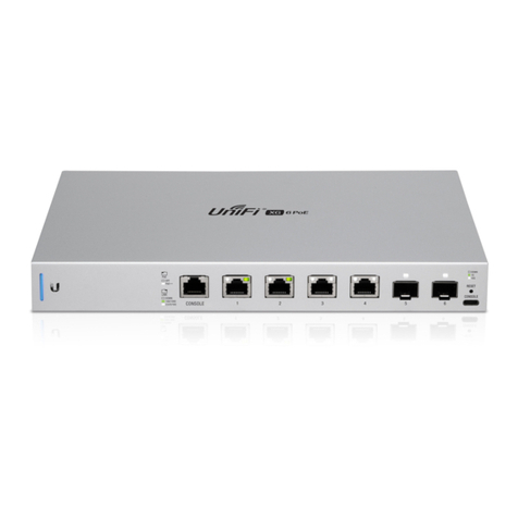
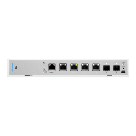
  9. Ubiquiti US-XG-6POE User manual

Ubiquiti US-XG-6POE User manual

20.12.2019 US-XG-6POE Quck Start Gude
https://dl.ubnt.com/qsg/US-XG-6POE/US-XG-6POE_EN.html 1/15
Un

F

Sw

tch Mount Brackets (Qty. 2) Bracket Screws (Qty. 8)
Mount

ng Screws (Qty. 4) Screw Anchors (Qty. 4) Power Adapter
Power Cord Cable Cl

p
Package Contents
System Requ

rements
L

nux, Mac OS X, or M

crosoft W

ndows 7/8/10
Java Runt

me Env

ronment 1.8 or above recommended
Web Browser: Google Chrome (Other browsers may have l

m

ted funct

onal

ty)
Un

F

Controller software v5.8.x (or newer), ava

lable at:
u

.com/download/un

f

Hardware Overv

ew
US-XG-6POE Qu

ck Start Gu

de
All manuals and user guides at all-guidesbox.com
all-guidesbox.com
20.12.2019 US-XG-6POE Quck Start Gude
https://dl.ubnt.com/qsg/US-XG-6POE/US-XG-6POE_EN.html 2/15
System LED
RJ45 PoE LED (Ports 1 - 4)
RJ45 L

nk/Speed/Act

v

ty LED (Ports 1 - 4)
Flash

ng Wh

te In

t

al

z

ng.
Steady Wh

te Factory defaults, wa

t

ng for adopt

on.
Alternat

ng Wh

te/Blue Dev

ce

s busy; do not touch or unplug

t. Th

s usually

nd

cates that a process such as a f

rmware upgrade

s
tak

ng place.
Steady Blue Successfully adopted by a network and work

ng
properly.
Flash

ng Blue
Th

s

s used to locate a dev

ce.
When you cl

ck Locate

n the Un

F

Controller
software, the System LED w

ll ash blue. The software
w

ll also d

splay the locat

on of the Un

F

Sw

tch on
the map.
Off PoE D

sabled
Wh

te 802.3af/at/bt PoE
Off No L

nk
US-XG-6POE Qu

ck Start Gu

de
All manuals and user guides at all-guidesbox.com
20.12.2019 US-XG-6POE Quck Start Gude
https://dl.ubnt.com/qsg/US-XG-6POE/US-XG-6POE_EN.html 3/15
SFP+ L

nk/Speed/Act

v

ty LED (Ports 5 - 6)
RJ45 Console Port
RJ45 (Ports 1 - 4)
SFP+ (Ports 5 - 6)
USB Console Port
Reset Button
Green L

nk Establ

shed at 1 Gbps
Flash

ng Ind

cates Act

v

ty
Wh

te L

nk Establ

shed at 10 Gbps
Flash

ng Ind

cates Act

v

ty
Off No L

nk
Green L

nk Establ

shed at 1 Gbps
Flash

ng Ind

cates Act

v

ty
Wh

te L

nk Establ

shed at 10 Gbps
Flash

ng Ind

cates Act

v

ty
RJ45 ser

al console port for Command L

ne Interface (CLI) management. Use an
RJ45-to-DB9, ser

al console cable, also known as a rollover cable, to connect the
Console port to your computer. Then conf

gure the follow

ng sett

ngs as needed:
Baud rate 115200
Data b

ts 8
Par

ty NONE
Stop b

ts 1
Flow control NONE
RJ45 ports support 100 Mbps or 1/2.5/5/10 Gbps Ethernet connect

ons and
802.3af/at/bt PoE output.
Hot-swappable SFP+ ports support 1/10 Gbps connect

ons.
USB Type C console port for Command L

ne Interface (CLI) management.
Th

s button serves two funct

ons for the Un

F

Sw

tch:
Restart
Press and release the Reset button qu

ckly.
US-XG-6POE Qu

ck Start Gu

de
All manuals and user guides at all-guidesbox.com
20.12.2019 US-XG-6POE Quck Start Gude
https://dl.ubnt.com/qsg/US-XG-6POE/US-XG-6POE_EN.html 4/15
DC Input
Power Port
Ground
Restore to Factory Default Sett

ngs
Press and hold the Reset button for more
than f

ve seconds.
Opt

onal DC

nput for connect

ng a stand-alone or redundant DC power source (not

ncluded) w

th m

n

mum power: 40W, 44 to 57VDC.
Note:
Ensure the polar

ty

s correct: red

s pos

t

ve (+) and black

s
negat

ve (-).
You can use the redundant DC power source as a hot spare;

f there

s no longer
power through the Power port, the Un

F

Sw

tch w

ll sw

tch to the DC power source
w

thout

nterrupt

ng

ts operat

on.
Connect the

ncluded Power Adapter to the Power port.
Anc

llary ground

ng po

nt for enhanced ESD protect

on.
Hardware Installat

on
The Un

F

Sw

tch can be mounted on a hor

zontal or vert

cal surface.
WARNING:
The US-XG-6POE must not be stacked. Do not place

t on top of
another sw

tch. Do not place anyth

ng on top of the US-XG-6POE.
Ground

ng (Recommended)
The Un

F

Sw

tch

s grounded through the Power Adapter; however, you can add
opt

onal ESD ground

ng for enhanced ESD protect

on.
Note:
You also have the opt

on to use the Cable Cl

p to secure the cord of the
Power Adapter. For

nstruct

ons, proceed to
"Us

ng the Cable Cl

p (Opt

onal)"
.
US-XG-6POE Qu

ck Start Gu

de
All manuals and user guides at all-guidesbox.com
20.12.2019 US-XG-6POE Quck Start Gude
https://dl.ubnt.com/qsg/US-XG-6POE/US-XG-6POE_EN.html 5/15
Us

ng the Cable Cl

p (Opt

onal)
1.
2.
US-XG-6POE Qu

ck Start Gu

de
All manuals and user guides at all-guidesbox.com
20.12.2019 US-XG-6POE Quck Start Gude
https://dl.ubnt.com/qsg/US-XG-6POE/US-XG-6POE_EN.html 6/15
3.
4.
Connect

ng Power
US-XG-6POE Qu

ck Start Gu

de
All manuals and user guides at all-guidesbox.com
all-guidesbox.com
20.12.2019 US-XG-6POE Quck Start Gude
https://dl.ubnt.com/qsg/US-XG-6POE/US-XG-6POE_EN.html 7/15
You have two opt

ons:
"Us

ng the Power Adapter"
"Us

ng the DC Input (Opt

onal)"
Us

ng the Power Adapter
1.
2.
Us

ng the DC Input (Opt

onal)
For stand-alone power or redundant backup, connect a DC power source to the Un

F

Sw

tch.
Note:
Only one power source can be used at any one t

me. W

th both power
sources connected, the

nput w

th the h

ghest voltage w

ll be used; the other
power source defaults to backup.
W

re a DC/DC cable (not

ncluded) to the DC Input. Ensure the polar

ty

s correct: red

s
pos

t

ve (+) and black

s negat

ve (-).
US-XG-6POE Qu

ck Start Gu

de
All manuals and user guides at all-guidesbox.com
20.12.2019 US-XG-6POE Quck Start Gude
https://dl.ubnt.com/qsg/US-XG-6POE/US-XG-6POE_EN.html 8/15
Connect

ng Ethernet
Connect

ng SFP+
1.
US-XG-6POE Qu

ck Start Gu

de
All manuals and user guides at all-guidesbox.com
20.12.2019 US-XG-6POE Quck Start Gude
https://dl.ubnt.com/qsg/US-XG-6POE/US-XG-6POE_EN.html 9/15
2.
3.
US-XG-6POE Qu

ck Start Gu

de
All manuals and user guides at all-guidesbox.com
20.12.2019 US-XG-6POE Quck Start Gude
https://dl.ubnt.com/qsg/US-XG-6POE/US-XG-6POE_EN.html 10/15
For

nformat

on about compat

ble f

ber SFP modules, v

s

t:
commun

ty.ubnt.com/un

f

Software Installat

on
Download and

nstall the latest vers

on of the Un

F

Controller software at
u

.com/download/un

f

and follow the on-screen

nstruct

ons.
Note: If you already have Un

F

Controller v5.8.x or newer

nstalled, sk

p to the
sect

on,
"Adopt

ng the Un

F

Sw

tch"
.
After you have

nstalled the software and run the Un

F

Installat

on W

zard, a log

n
screen w

ll appear for the Un

F

Controller management

nterface. Enter the adm

n
name and password that you created and cl

ck S

gn In.
US-XG-6POE Qu

ck Start Gu

de
All manuals and user guides at all-guidesbox.com
20.12.2019 US-XG-6POE Quck Start Gude
https://dl.ubnt.com/qsg/US-XG-6POE/US-XG-6POE_EN.html 11/15
You can manage your network and v

ew network stat

st

cs us

ng the Un

F

Controller
management

nterface.
To adopt the Un

F

Sw

tch, proceed to the sect

on,
"Adopt

ng the Un

F

Sw

tch"
.
For

nformat

on on conf

gur

ng and us

ng the Un

F

Controller software, refer to the
User Gu

de on the webs

te:
u

.com/download/un

f

Adopt

ng the Un

F

Sw

tch
1. From the Un

F

Controller dashboard, cl

ck Dev

ces

n the left menu bar.
2. On the Dev

ces screen, locate the Un

F

Sw

tch

n the l

st of dev

ces under the Model
column. To adopt the Un

F

Sw

tch, cl

ck Adopt.
US-XG-6POE Qu

ck Start Gu

de
All manuals and user guides at all-guidesbox.com
all-guidesbox.com
20.12.2019 US-XG-6POE Quck Start Gude
https://dl.ubnt.com/qsg/US-XG-6POE/US-XG-6POE_EN.html 12/15
3. The System LED on the Un

F

Sw

tch w

ll turn blue to conf

rm that

t has been
successfully adopted.
Spec

f

cat

ons
US-XG-6POE
D

mens

ons 165 x 268.1 x 31.8 mm
(6.50 x 10.56 x 1.25")
We

ght 1.3 kg (2.87 lb)
Interfaces
Network

ng (4) 100 Mbps or 1/2.5/5/10G RJ45 Ports
(2) 1/10G SFP+ Ethernet Ports
Management Ethernet In-Band
(1) RJ45 Ser

al Port Out-of-Band
(1) USB Type C Port Out-of-Band
Power Method 54VDC, 3.88A Power Adapter (Included)
or 44 to 57VDC, 5.56A DC Input w

th Term

nal Block
Power Supply External AC/DC Adapter (Included)
or
DC Power Source
Supported Voltage Range 44 to 57VDC
Max. Power Consumpt

on
(Exclud

ng PoE Output) 40W
LEDs
System Status
RJ45 Data Ports PoE; Speed/L

nk/Act

v

ty
SFP+ Data Ports L

nk/Act

v

ty
ESD/EMP Protect

on A

r: ± 18 kV, Contact: ± 12 kV
Shock and V

brat

on ETSI300-019-1.4 Standard
Operat

ng Temperature -5 to 45° C (23 to 113° F)
US-XG-6POE Qu

ck Start Gu

de
All manuals and user guides at all-guidesbox.com
20.12.2019 US-XG-6POE Quck Start Gude
https://dl.ubnt.com/qsg/US-XG-6POE/US-XG-6POE_EN.html 13/15
US-XG-6POE
Operat

ng Hum

d

ty 5 to 95% Noncondens

ng
Cert

f

cat

ons CE, FCC, IC
PoE
PoE Interfaces PoE++ IEEE 802.3bt
(Pa

r A 1, 2+; 3, 6-) (Pa

r B 4 , 5+; 7, 8-)
Max. 802.3bt Wattage per Port by
PSE 60W
Voltage Range 802.3af Mode 44-57V
Voltage Range 802.3at/bt Mode 50-57V
Safety Not

ces
1. Read, follow, and keep these

nstruct

ons.
2. Heed all warn

ngs.
3. Only use attachments/accessor

es spec

f

ed by the manufacturer.
WARNING:
Fa

lure to prov

de proper vent

lat

on may cause f

re hazard. Keep at least 20
mm of clearance next to the vent

lat

on holes for adequate a

row.
WARNING:
To reduce the r

sk of f

re or electr

c shock, do not expose th

s product to ra

n
or mo

sture.
WARNING:
Do not use th

s product

n locat

on that can be submerged by water.
WARNING:
Avo

d us

ng th

s product dur

ng an electr

cal storm. There may be a remote
r

sk of electr

c shock from l

ghtn

ng.
Electr

cal Safety Informat

on
1. Compl

ance

s requ

red w

th respect to voltage, frequency, and current requ

rements

nd

cated
on the manufacturer’s label. Connect

on to a d

fferent power source than those spec

f

ed may
result

n

mproper operat

on, damage to the equ

pment or pose a f

re hazard

f the l

m

tat

ons
are not followed.
2. There are no operator serv

ceable parts

ns

de th

s equ

pment. Serv

ce should be prov

ded only
by a qual

f

ed serv

ce techn

c

an.
3. Th

s equ

pment

s prov

ded w

th a detachable power cord wh

ch has an

ntegral safety ground
w

re

ntended for connect

on to a grounded safety outlet.
a. Do not subst

tute the power cord w

th one that

s not the prov

ded approved type. Never
use an adapter plug to connect to a 2-w

re outlet as th

s w

ll defeat the cont

nu

ty of the
ground

ng w

re.
b. The equ

pment requ

res the use of the ground w

re as a part of the safety cert

f

cat

on,
mod

f

cat

on or m

suse can prov

de a shock hazard that can result

n ser

ous

njury or death.
US-XG-6POE Qu

ck Start Gu

de
All manuals and user guides at all-guidesbox.com
20.12.2019 US-XG-6POE Quck Start Gude
https://dl.ubnt.com/qsg/US-XG-6POE/US-XG-6POE_EN.html 14/15
c. Contact a qual

f

ed electr

c

an or the manufacturer

f there are quest

ons about the

nstallat

on pr

or to connect

ng the equ

pment.
d. Protect

ve earth

ng

s prov

ded by L

sted AC adapter. Bu

ld

ng

nstallat

on shall prov

de
appropr

ate short-c

rcu

t backup protect

on.
e. Protect

ve bond

ng must be

nstalled

n accordance w

th local nat

onal w

r

ng rules and
regulat

ons.
L

m

ted Warranty
u

.com/support/warranty
The l

m

ted warranty requ

res the use of arb

trat

on to resolve d

sputes on an

nd

v

dual bas

s, and,
where appl

cable, spec

fy arb

trat

on

nstead of jury tr

als or class act

ons.
Compl

ance
FCC
Changes or mod

f

cat

ons not expressly approved by the party respons

ble for compl

ance could
vo

d the user’s author

ty to operate the equ

pment.
Th

s dev

ce compl

es w

th Part 15 of the FCC Rules. Operat

on

s subject to the follow

ng two
cond

t

ons.
1. Th

s dev

ce may not cause harmful

nterference, and
2. Th

s dev

ce must accept any

nterference rece

ved,

nclud

ng

nterference that may cause
undes

red operat

on.
Th

s equ

pment has been tested and found to comply w

th the l

m

ts for a Class A d

g

tal dev

ce,
pursuant to Part 15 of the FCC Rules. These l

m

ts are des

gned to prov

de reasonable protect

on
aga

nst harmful

nterference when the equ

pment

s operated

n a commerc

al env

ronment. Th

s
equ

pment generates, uses, and can rad

ate rad

o frequency energy and,

f not

nstalled and used

n accordance w

th the

nstruct

on manual, may cause harmful

nterference to rad

o
commun

cat

ons. Operat

ons of th

s equ

pment

n a res

dent

al area

s l

kely to cause harmful

nterference

n wh

ch case the user w

ll be requ

red to correct the

nterference at h

s own expense.
ISED Canada
CAN ICES-3(A)/NMB-3(A)
Austral

a and New Zealand
Warn

ng: Th

s equ

pment

s compl

ant w

th Class A of CISPR 32. In a res

dent

al
env

ronment th

s equ

pment may cause rad

o

nterference.
CE Mark

ng
CE mark

ng on th

s product represents the product

s

n compl

ance w

th all d

rect

ves that are
appl

cable to

t.
US-XG-6POE Qu

ck Start Gu

de
All manuals and user guides at all-guidesbox.com
20.12.2019 US-XG-6POE Quck Start Gude
https://dl.ubnt.com/qsg/US-XG-6POE/US-XG-6POE_EN.html 15/15
WEEE Compl

ance Statement
Declarat

on of Conform

ty
Onl

ne Resources
© 2019 Ub

qu

t

Inc. All r

ghts reserved.
US-XG-6POE Qu

ck Start Gu

de
All manuals and user guides at all-guidesbox.com

Other manuals for US-XG-6POE

6

Other Ubiquiti Switch manuals

Ubiquiti UniFi Switch 24 US-24-250W User manual

Ubiquiti

Ubiquiti UniFi Switch 24 US-24-250W User manual

Ubiquiti UniFi US-24-250W User manual

Ubiquiti

Ubiquiti UniFi US-24-250W User manual

Ubiquiti EdgePoint S16 User manual

Ubiquiti

Ubiquiti EdgePoint S16 User manual

Ubiquiti UniFi Switch 48-500W User manual

Ubiquiti

Ubiquiti UniFi Switch 48-500W User manual

Ubiquiti TS-16-CARRIER User manual

Ubiquiti

Ubiquiti TS-16-CARRIER User manual

Ubiquiti EdgeSwitch ES-16-XG User manual

Ubiquiti

Ubiquiti EdgeSwitch ES-16-XG User manual

Ubiquiti US-XG-6POE User manual

Ubiquiti

Ubiquiti US-XG-6POE User manual

Ubiquiti TS-5-POE ToughSwitchPoE User manual

Ubiquiti

Ubiquiti TS-5-POE ToughSwitchPoE User manual

Ubiquiti EdgeSwitch 16 XG User manual

Ubiquiti

Ubiquiti EdgeSwitch 16 XG User manual

Ubiquiti EdgeSwitch ES-16-XG User manual

Ubiquiti

Ubiquiti EdgeSwitch ES-16-XG User manual

Ubiquiti ES-24-250W Instruction Manual
Ubiquiti

Ubiquiti ES-24-250W Instruction Manual

Ubiquiti EdgeSwitch User manual

Ubiquiti

Ubiquiti EdgeSwitch User manual

Ubiquiti UniFi USW-16-POE User manual

Ubiquiti

Ubiquiti UniFi USW-16-POE User manual

Ubiquiti TS-16-CARRIER User manual

Ubiquiti

Ubiquiti TS-16-CARRIER User manual

Ubiquiti EdgeSwitch 48 User manual

Ubiquiti

Ubiquiti EdgeSwitch 48 User manual

Ubiquiti UniFi USW-Industral Guide

Ubiquiti

Ubiquiti UniFi USW-Industral Guide

Ubiquiti UniFi US-24-250W User manual

Ubiquiti

Ubiquiti UniFi US-24-250W User manual

Ubiquiti US-16-XG User manual

Ubiquiti

Ubiquiti US-16-XG User manual

Ubiquiti US-16-XG User manual

Ubiquiti

Ubiquiti US-16-XG User manual

Ubiquiti UniFi USW-Industrial User manual

Ubiquiti

Ubiquiti UniFi USW-Industrial User manual

Ubiquiti TS-5-POE ToughSwitchPoE User manual
Ubiquiti

Ubiquiti TS-5-POE ToughSwitchPoE User manual

Ubiquiti ES-24-250W User manual

Ubiquiti

Ubiquiti ES-24-250W User manual

Ubiquiti US-48 User manual

Ubiquiti

Ubiquiti US-48 User manual
Ubiquiti UniFi USW-Pro-24-POE User manual

Ubiquiti

Ubiquiti UniFi USW-Pro-24-POE User manual

Popular Switch manuals by other brands

Champion CH2020 user manual

Champion

Champion CH2020 user manual

Hayward VS Omni HLXHUBCASE owner's manual

Hayward

Hayward VS Omni HLXHUBCASE owner's manual

Cisco Nexus 7004 Hardware  installation and reference guide

Cisco

Cisco Nexus 7004 Hardware installation and reference guide

Dell PowerEdge M IO Aggregator Getting started guide

Dell

Dell PowerEdge M IO Aggregator Getting started guide

Conceptronic CS4USB2 quick guide

Conceptronic

Conceptronic CS4USB2 quick guide

Festo VABF-S4-A2G2 Series Assembly instructions

Festo

Festo VABF-S4-A2G2 Series Assembly instructions

Quintum A Series A400 release note

Quintum

Quintum A Series A400 release note

Supermicro SSE-X3348S Configuration guide

Supermicro

Supermicro SSE-X3348S Configuration guide

Lindy Presentation Switch Pro user manual

Lindy

Lindy Presentation Switch Pro user manual

Intermatic T1905 supplementary guide

Intermatic

Intermatic T1905 supplementary guide

ZyXEL Communications GS1900-8 user guide

ZyXEL Communications

ZyXEL Communications GS1900-8 user guide

Cisco 4506 - Catalyst Switch supplementary guide

Cisco

Cisco 4506 - Catalyst Switch supplementary guide

Gefen HDMI user manual

Gefen

Gefen HDMI user manual

Ortech DWOS quick start guide

Ortech

Ortech DWOS quick start guide

NKK SWITCHES IS-S04G1LC-S user manual

NKK SWITCHES

NKK SWITCHES IS-S04G1LC-S user manual

FM Systems DVS702 installation manual

FM Systems

FM Systems DVS702 installation manual

CTS HES-3109 Series user manual

CTS

CTS HES-3109 Series user manual

ATEN KE6900 user manual

ATEN

ATEN KE6900 user manual

manuals.online logo
manuals.online logoBrands
  • About & Mission
  • Contact us
  • Privacy Policy
  • Terms and Conditions

Copyright 2025 Manuals.Online. All Rights Reserved.