4
IT
devono essere assolutamente di tipo meccanico e svincolati da qual-
siasi potenziale, non sono ammessi collegamenti a stadi tipo quelli
deniti ”PNP”, ”NPN”, ”Open Collector” ecc. ecc.
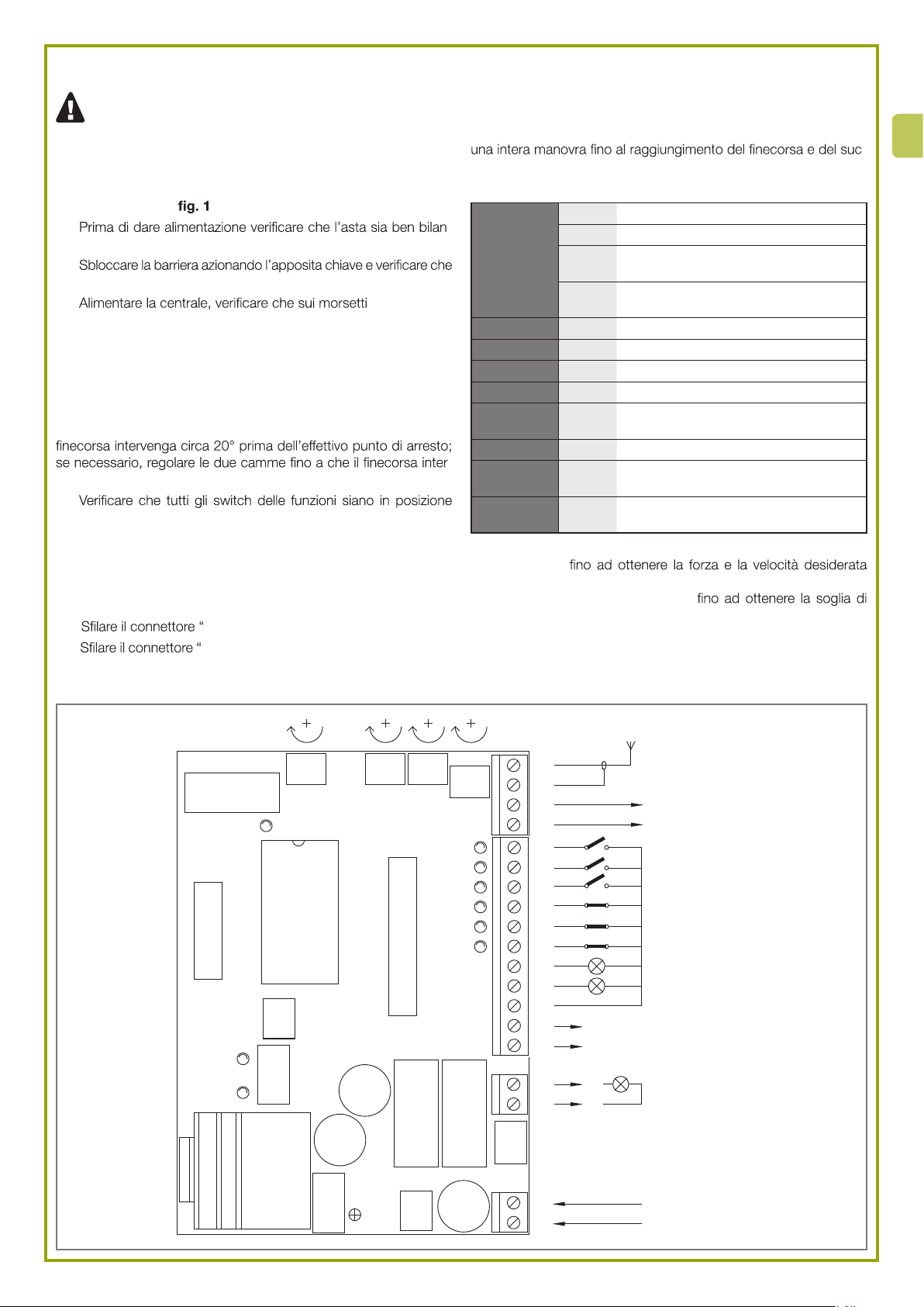
01. Effettuare i collegamenti necessari seguendo lo schema di g. 3;
si ricorda che vi sono delle normative precise da rispettare in modo
rigoroso sia per quanto riguarda la sicurezza degli impianti elettrici
che per quanto riguarda i cancelli automatici.
02. Vericare che l’asta sia ben bilanciata, eventualmente regolare la
molla di bilanciamento.
03. Sbloccare la barriera agendo nell’apposita chiave e vericare che
l’asta si possa muovere senza particolari sforzi per tutta la sua corsa.
ATTENZIONE! - Non alimentare la barriera senza rispet-
tare tutte le norme per la categoria dei cancelli automatici!
04. Alimentare la centrale vericando immediatamente che sui mor-
setti 1-2 giunga una tensione di 230 Vca e che sui morsetti 5-6 sia
presente una tensione di 24 Vcc. Non appena la centrale è alimenta-
ta le spie luminose (LED) che sono poste sugli ingressi attivi devono
illuminarsi, inoltre dopo pochi istanti il led ”OK” dovrà iniziare a lam-
peggiare con cadenza regolare. Se tutto questo non avviene, togliere
immediatamente alimentazione e controllare con maggior attenzione
i collegamenti.
05. Controllare la corrispondenza dei due led FCA e FCC, quando
l’asta è chiusa deve spegnersi solo FCC, quando è aperta deve spe-
gnersi solo il led FCA. Per sfruttare la funzione di rallentamento è
necessario che il necorsa intervenga circa 20° prima dell’effettivo
punto di arresto; se necessario, regolare le due camme no a che il
necorsa interviene nel punto desiderato.
06. Ora vericare che i led relativi agli ingressi con contatti tipo NC si-
ano accesi (tutte le sicurezze attive) e che i led relativi ad ingressi tipo
NA siano spenti (nessun comando presente), se questo non avviene
controllare i collegamenti e l’efcienza dei vari dispositivi.
07. Vericare il corretto funzionamento di tutti i dispositivi di sicurezza
presenti nell’impianto (arresto di emergenza, fotocellule,coste pneu-
matiche ecc.), ogni volta che intervengono, il relativi led ALT, FOTO
o FOTO 2 devono spegnersi.
08. Vericare che tutti gli switch delle funzioni siano in posizione ”Off”
in questo modo il funzionamento è in modo manuale cioè a tasto
premuto, bloccare la barriera con l’asta a 45° in modo che possa
muoversi liberamente nei due sensi di marcia, quindi dare un breve
impulso di comando sull’ingresso APRE, ora se l’asta non si è mossa
nel senso di apertura occorre procedere come segue:
1) Spegnere l’alimentazione elettrica alla barriera
2) Slare il connettore “MOTORE” e reinserirlo ruotato di 180°
3) Slare il connettore “FINE CORSA” e reinserirlo ruotato di 180°
09. Eseguito quanto descritto conviene riprovare se il senso di rota-
zione ora è corretto ripetendo l’operazione del punto “G”.
Nota: quando si inverte il senso del movimento, occorre eseguire
tutte le tre operazioni descritte sopra. In particolare, se ad esempio,
si ruota il connettore ”MOTORE” e non si ruota il connettore ”FINE
CORSA” si provoca un errore nel sistema di rallentamento. In questo
caso, il motore è comandato, ad esempio in apertura, ma il necorsa
FCA non viene mai raggiunto e di conseguenza l’asta raggiunge il
punto di apertura con la massima forza, quindi interviene il sistema di
rilevazione amperometrica che inverte il moto in una nuova manovra
anche questa sbagliata.
10. Regolare provvisoriamente i trimmer STOP_AMPERE e FORZA
LAVORO al massimo della corsa, TEMPO PAUSA al minimo, rego-
lare poi FORZA RALLENTAMENTO a metà corsa.
11. Provare ad eseguire una intera manovra no a che l’asta rag-
giunge il punto di intervento del necorsa, ora deve entrare in gioco
il rallentamento che permette il proseguimento della corsa ad una
velocità ridotta per altri 3 secondi.
12. Regolare i Trimmer FORZA LAVORO e FORZA RALLENTA-
MENTO per ottenere che la manovra avvenga con la velocità e la
spinta desiderata e che la fase di rallentamento sia tale che l’asta
raggiunga i punti di arresto nel modo più ”dolce” possibile e senza
scossoni; naturalmente una perfetta regolazione della molla di bilan-
ciamento è fondamentale.
13. Alla ne, regolare il trimmer STOP_AMPERE in modo che il si-
stema di rilevazione degli ostacoli basato su frizione amperometrica
intervenga non appena all’asta viene applicata una appropriata azio-
ne contraria. Il sistema di frizione amperometrica interviene nei due
sensi del movimento.
3.2 - Prova di funzionamento
Vericati i collegamenti ed eseguita la fase di controllo (Cap. 3.1) è
possibile provare il movimento comandato elettricamente dell’asta, in
questo caso si consiglia di operare in modo manuale con tutte le
funzioni disattivate (tutti gli Switch Off); per ogni eventualità, in modo
manuale, rilasciando il tasto di comando si ottiene l’immediato arresto
del motore. Se si usa come comando l’ingresso Passo P. il primo mo-
vimento (dopo l’accensione) dovrà essere in apertura.
Agendo sugli ingressi di comando movimentare l’asta no al punto
di apertura, a circa 20° prima del punto di fermata deve scattare il
necorsa FCA che attiva la fase di”rallentamento”che permette di rag-
giungere il punto previsto con una velocità ridotta.
Eseguire poi un movimento in chiusura no al raggiungimento del
punto di chiusura anche in questo casi dovrà intervenire il necorsa
FCC che attiva la fase di rallentamento 20° prima dell’arresto del mo-
vimento. Passare ora a provare l’intervento dei dispositivi di sicurezza,
FOTO in apertura non ha alcun effetto, in chiusura provoca la fermata
dell’asta; FOTO 2 in chiusura non ha alcun effetto, in apertura pro-
voca la fermata dell’asta. I dispositivi collegati nell’ingresso ALT agi-
scono sia in apertura che in chiusura provocando sempre la fermata
dell’asta.
Le normative italiane UNI 8612 prescrivono che la spinta massima di
una automazione non superi i 150 N (~ 13,5 Kg) questo si ottiene me-
diante la regolazione della frizione amperometrica STOP_AMPERE.
Sulla scheda è presente un trimmer che permette di stabilire la soglia
di intervento della frizione; deve essere regolato in modo che interven-
ga non appena all’asta viene applicata una leggera forza in direzione
contraria al movimento in corso.
Per superare la fase di inizio del movimento che richiede sempre una
maggiore potenza dal motore Il sistema di frizione STOP_AMPERE
viene escluso nella fase di partenza del motore; per valutare l’effetto
della regolazione sul trimmer conviene quindi attendere che il movi-
mento sia avviato e che l’asta abbia raggiunto la velocità standard.
Attenzione anche al fatto che, sempre per questioni di sicurezza, se la
frizione interviene per tre volte consecutive il movimento viene fermato
senza eseguire l’inversione.
Se viene selezionato il modo di funzionamento in automatico al termi-
ne della manovra di apertura si esegue una “pausa” al termine della
quale viene attivata automaticamente una manovra di chiusura. Il tem-
po di pausa è regolabile attraverso l’apposito trimmer TEMPO PAU-
SA. La pausa viene attivata anche nel movimento in semiautomatico
quando, in chiusura, l’intervento di un dispositivo di sicurezza o della
frizione STOP_AMPERE provoca una inversione in apertura.
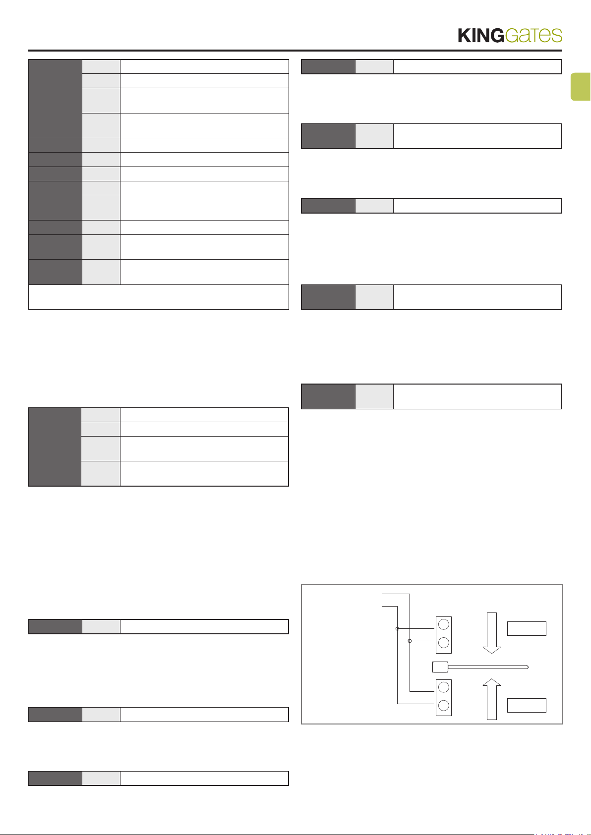
3.3 - Regolazione del tempo pausa
Quando viene selezionata attraverso l’apposito dip-switch la funzione
di chiusura automatica (Vedi Cap. 3.3), dopo una manovra di apertura
viene attivato un temporizzatore che controlla il cosiddetto ”Tempo
Pausa”, allo scadere del tempo si attiva automaticamente una ma-
novra di chiusura. Questo tempo può essere regolato con il trimmer
TEMPO PAUSA entro valori da 3 a 120 Secondi.
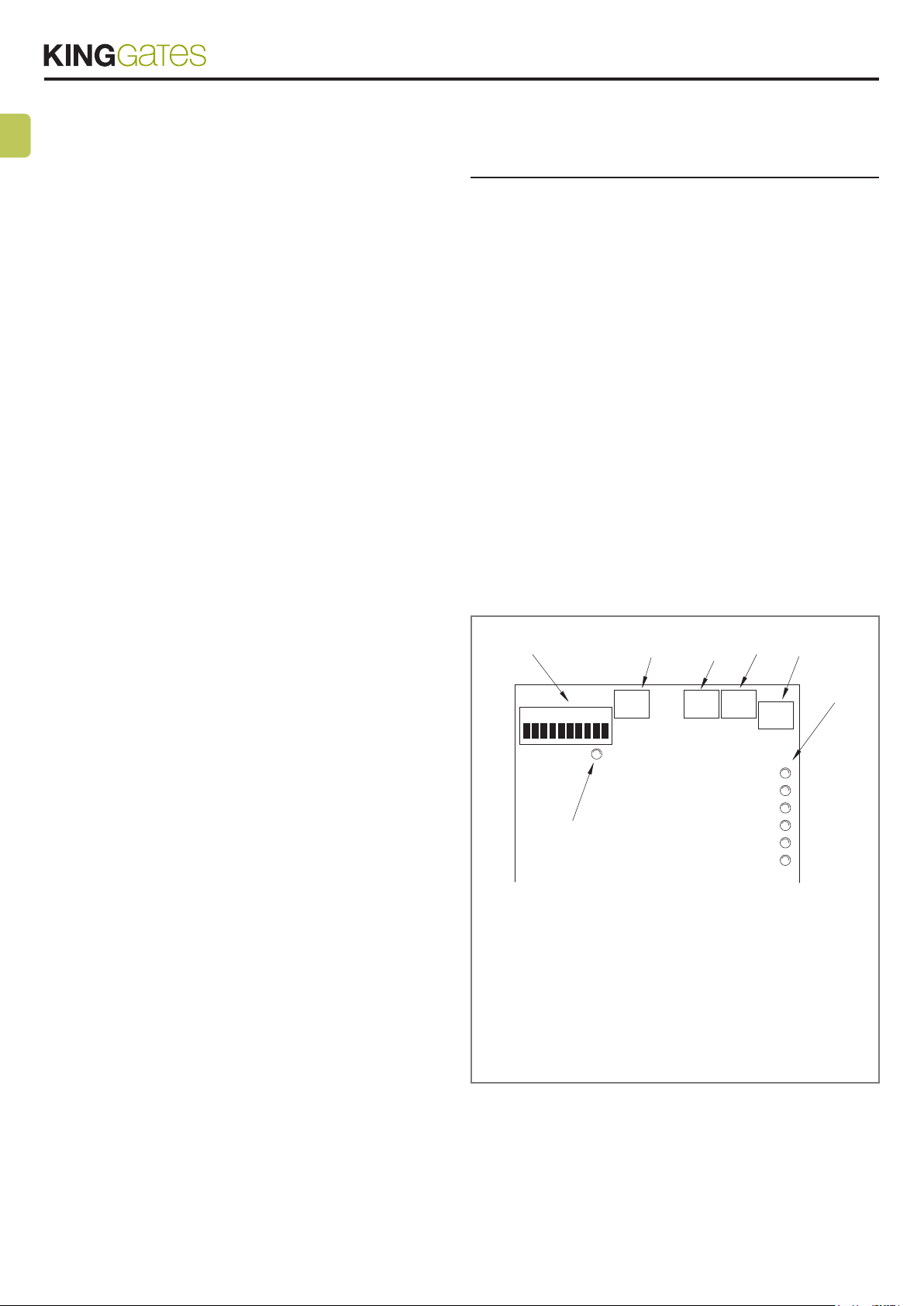
3.4 - Funzioni selezionabili
Il dip-switch FUNZIONI permette di selezionare i vari modi di funziona-
mento possibili e di inserire le funzioni desiderate.