PRELIMINARY CHECKS
- Read carefully all parts of this manual.
- Check that the product was not damaged during transportation.
- Check that the electrical plants is conforming to the characteristics required by the gear motor.
- Check that an adequate grounding plant exists and that all metallic parts are connected to this plant.
A wrong installation can produce serious damages or wounds.
ATTENTION: For any reason whatsoever never disassemble the barrier’s arm when it is in the horizontal position
ATTENTION: For any reason whatsoever never carry out an emergency or manual manoeuvre if the barrier arm is not
assembled
ATTENTION: For any reason whatsoever never carry out an emergency or manual manoeuvre with the gear motor in movement.
Locate the point inside the property where the Space4000 barrier will be installed.
Construct a solid concrete base with proper dimensions for the fixation of the base of the barrier providing a passage for the
sheath of power cables and system controls. Before the concrete sets, position the “Ps” plate (Optional) well down into the
concrete making sure that the plate is correctly oriented and perfectly horizontal on both axis (figure 1)
If a flat solid base is already available on the ground, the barrier can be fixed directly to the base by screws and fixing plugs
without using the “Ps” plate.
Use the “M” key to remove the protection carter “Cp” (Figure 2), remove the anterior door “P” (Figure 3) getting access to the
fixing holes onto the barrier’s base
�
BOX FIXING
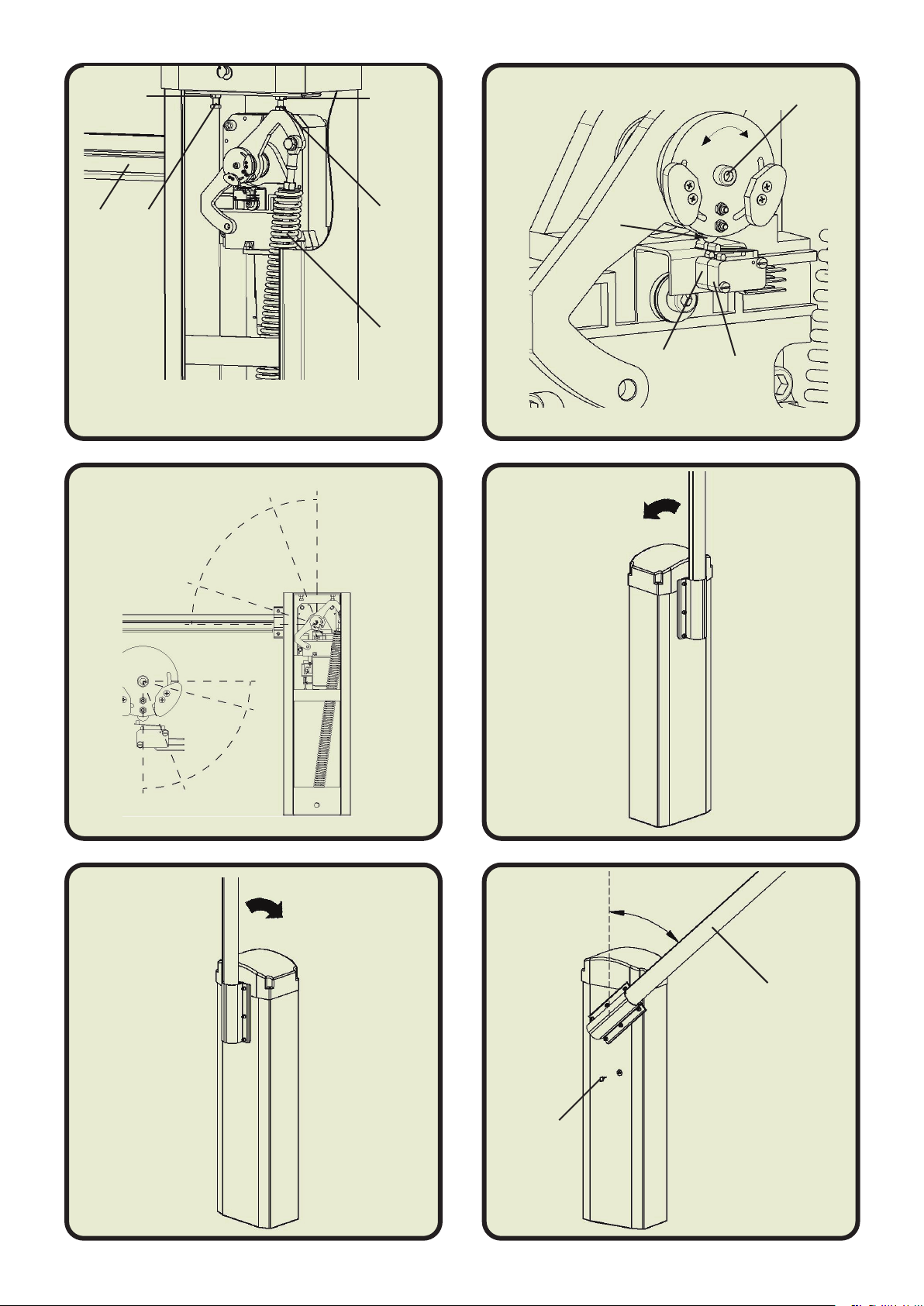
Choose the desired closing direction to the barrier’s arm “As” (Figure 10 counter clockwise or Figure 11 - clockwise) . If
necessary, loosen the upper and lower locking nuts of the spring “Mb”, unload completely the spring by turning it in the counter
clockwise sense (Figure 4), unscrewing completely the screw “V1” (Figure 4, Figure 5) move the spring “Mb” to the other
extremity of the plate “Pm” (Figure 4, Figure 5).
If the chosen closing direction to the barrier’s arm “As” is as shown in the Figure 11, the motor’s power cable must be connected
to the control unit as following:
Brown wire in the clamp 36
Blue wire in the clamp 37
If the chosen closing direction to the barrier’s arm “As” is as shown in the Figure 10, the motor’s power cable must be connected
to the control unit as following:
Brown wire in the clamp 37
Blue wire in the clamp 36
When the barrier’s arm is closed, the spring “Mb” must be in tension (Figure 4, Figure 5) , vice versa, when the barrier’s arm is
opened, the spring “Mb” must be almost unloaded (Figure 11, Figure 12)
ATTENTION: The spring “Mb” (Figure 4, Figure 5) must be completely unload before unscrewing “V1”.
CHOISE OF THE WAY OF THE ARM
(Only for barrier’s arm equipped with light stripe and/or sensitive rubber)
Bend to 90° the final extremity of the cable that comes out of the barrier’s arm “As”.
(Only for barrier’s arm equipped with light stripe)
Pass the cable from the outside toward the inside of barrier’s body thought the hole of the plate of fixing arm “C” (Figure 6).
(Only for barrier’s arm equipped with light stripe)
Take the cable’s extremity that has gone inside the barrier’s body and make it pass into the vain of the control unit.
Fix the barrier’s arm and the plates “B” and “B1” using 4 bolts M8x16 (“Z” – Figure 6) and 4 washers M8. Pay attention to not
crush the cables between the plates “C” and “B1” (Figure 6)
(Only for barrier’s arm equipped with light stripe)
Connect the light stripe cable in the control unit. The white wire into clamp 27 and the green wire into common (+) clamp 31 or
32. Set the dip parameters 7 and 8 as desired following the instructions in the central unit handbook.
ARM ASSEMBLY
Put the barrier’s arm in the horizontal position and check if the stop switch “Ms1” is committed by the cam “Cs” (Figure 9), if this
doesn’t happen, loosen the screw “V2” and rotate the disk support to do so that the cam “Cs” press the stop switch “Ms1”.
Tighten the screw “V2”.
Bring the barrier’s arm “As” in the position of around 45° (Figure 13), and block it turning the unblocking key “M1” in the
clockwise sense.
SWITCH REGOLATION
INSTALLATION
Unblock the barrier’s arm “As” turning the unblocking key “M1” (Figure 6) in counter clockwise sense (Slightly pushing the
barrier’s arm, it must freely move for the whole 90° run).
Using two 17 mm spanners, loosen the locking nut “D1” and screw in or out the adjusting screw “F1” until the desired horizontal
stop position is obtained and then tighten the nut “D1” (Figure 8).
Bring the barrier’s arm to the vertical position, loosen the nut “D2” and adjust the stop “F2” until the desired vertical stop position
is obtained and then tighten the nut “D2” (Figure 8). Once the above operation is terminated, carry out a manual opening and
closure manoeuvre to check that the mechanical stops are in the correct position.
ADJUSTMENT OF THE TRAVEL