King Quest VQ4100 User manual

For use with DIRECTV®satellite programming
VQ4100 Owner’s Manual
This manual contains detailed information on your KING Quest.
To start using your KING Quest right away,
see the Quick Reference Guide.
QUESTTM


Page 1
INTRODUCTION..................................................2
UNBOXANTENNA................................................3
APPLY RUBBER FEET .............................................3
POSITION ANTENNA ..............................................4
OBSERVE CAUTIONS WHEN CONNECTING ANTENNA .................5
CONNECT ANTENNA BASED ON RECEIVER: PAGE 6 OR 7 ............ 6-7
CONFIGURERECEIVER...........................................8
SCANFORSATELLITES......................................... 8-9
ENABLE THE ALARM (OPTIONAL) ................................10-11
SECURE THE ANTENNA ..........................................12
TROUBLESHOOTING ............................................12
OPTIONAL ROOF-MOUNT...................................... 13-17
ACCESSORIES .................................................18
LIMITEDWARRANTY.............................................19
FCCGUIDELINES ...............................................20
The satellite TV market is expanding and changing. The information in this manual
was accurate at the time of printing. If your KING Quest Satellite Antenna does not
operate as outlined in this manual, please call KING®at (952) 345-8147 or visit our
website at kingconnect.com.
KING is not responsible for changes outside of its control.
PRODUCT REGISTRATION
To provide ongoing technical support and to better
facilitate warranty processing, please register your product at
kingconnect.com/support.
CONTENTS
!

Page 2
Thank you for choosing the
KING Quest Portable HDTV System!
INTRODUCTION
IMPORTANT SAFETY AND CARE INFORMATION
QUESTIONS? (952) 345-8147
1. Keep the Quick Reference Guide and Installation Guide that came with your KING Quest in a
safe place for future reference. You may also print this on-line manual and keep it for future
reference as well.
2. Follow all instructions and warnings. Set up and operate the KING Quest in accordance with the
instructions.
3. To avoid risk of electric shock, unplug your receiver before connecting/disconnecting the KING
Quest in damp or wet conditions.
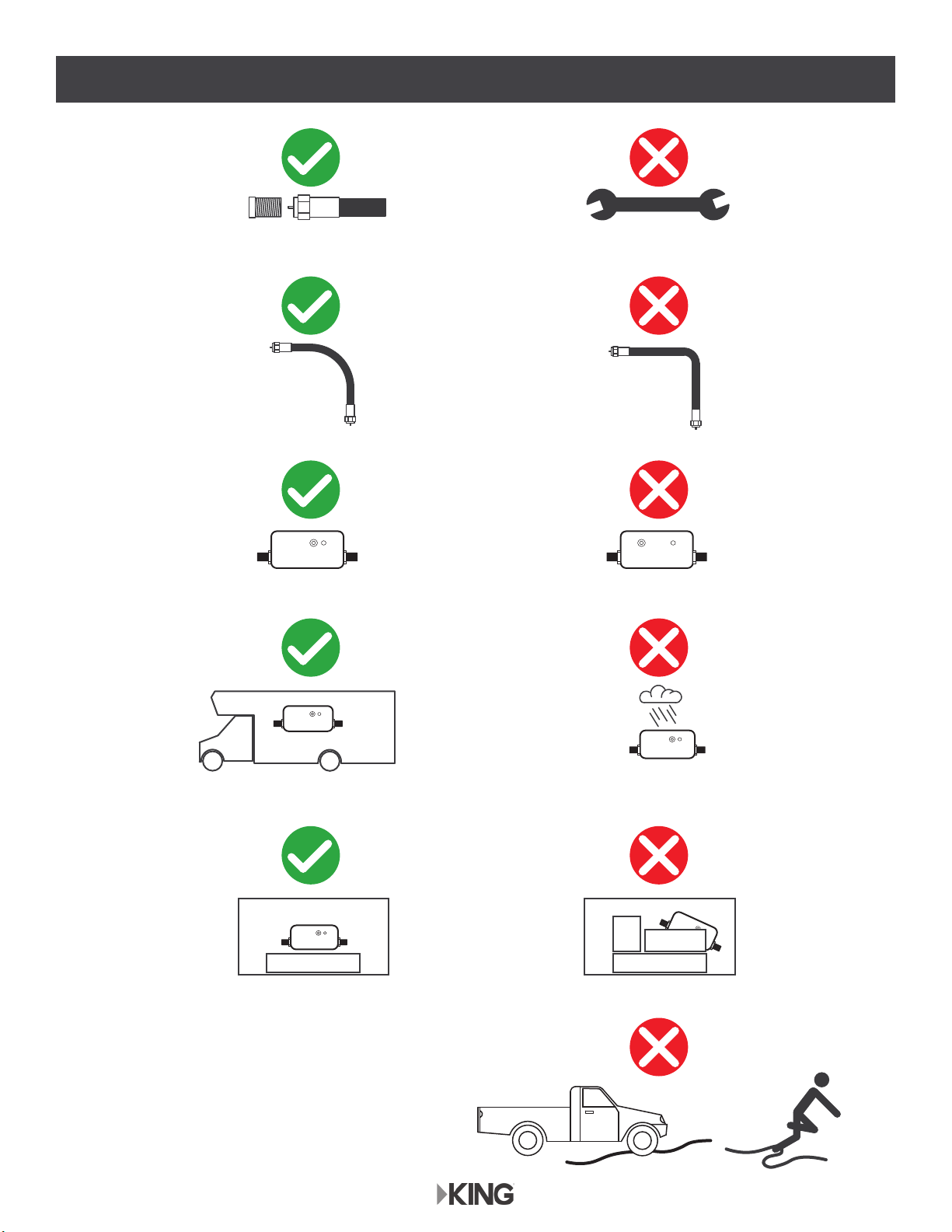
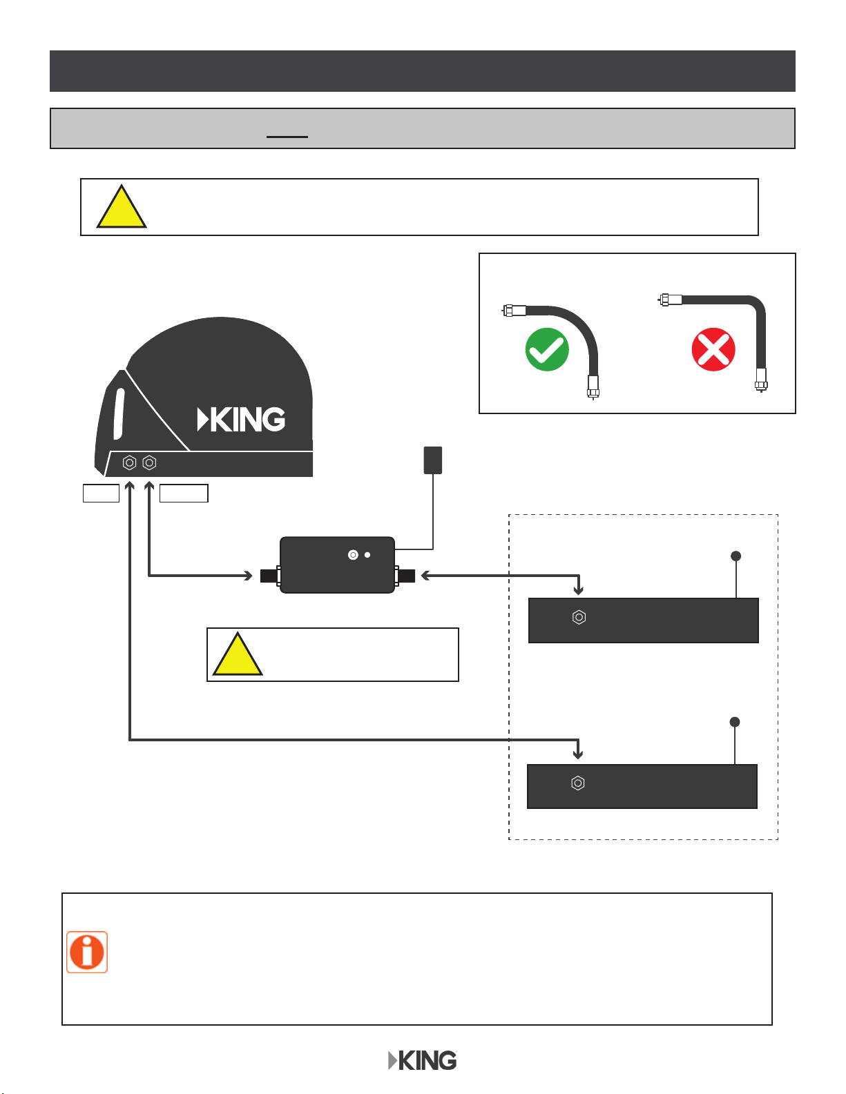
4. Tighten all of the coax cable connections by hand only. If you use a wrench, you may
over-tighten the connections and damage your equipment.
5. Always handle the KING Quest carefully. Do not drop the KING Quest. Avoid excessive shock
or vibration to the KING Quest.
6. Use caution when carrying the KING Quest. Always carry the KING Quest by the handle.
7. Do not remove the cover of the KING Quest without authorization. Doing so will void the limited
warranty.
8. Do not stack the KING Quest on top of or below other electronic devices as this can cause heat
build-up or block the satellite signal from reaching the KING Quest.
9. Do not operate or store near any indoor or outdoor heat source such as radiators, heat registers,
VWRYHVEDUEHFXHVFDPS¿UHVRURWKHULWHPVWKDWSURGXFHKHDW
10. Servicing may be required if the unit has been dropped or damaged in any way or if the unit does
not operate normally. Call KING Customer Service at (952) 345-8147.
11. Do not power wash the KING Quest.
12. Do not submerge the KING Quest or place in standing water.
13. Keep the enclosure clean from dirt, bugs, and other debris by hand washing with mild soap and
water.
14. Do not coat or paint the KING Quest with any substance.
The KING Quest has been designed to be maintenance and trouble free. If not using the KING Quest
for long periods of time, it is recommended that you set up the system on a quarterly basis (every
three months) to keep all moving parts of the KING Quest in good working order.
If you have any comments or questions, please contact KING Customer Service at (952) 345-8147,

Page 3
Do not
apply here.
Apply (3)
rubber feet
Soft, non-scratching surface
KC1153
UNBOX ANTENNA
APPLY RUBBER FEET
You will also need (sold separately):
DIRECTV
Programming Subscription
3 Rubber Feet
(taped to handle)
Power Inserter with Power Supply
Installation
Guide
Registration
Card
Antenna Unit
DIRECTV Receiver*
*For the most up-to-date receiver compatibility information, go to kingconnect.com/support.
Cable(s) KC1356
TV
Short
Coax Cable
50’ RG-6
Coax Cable
Quick
Reference
Guide
Do not apply rubber feet if roof-mounting the antenna unit.
See OPTIONAL ROOF-MOUNT Section.

Page 4
ANTENNA
UNIT
SATELLITES IN
SOUTHERN SKY
KC1271
ANTENNA
UNIT
OBSTRUCTIONS
SATELLITES IN
SOUTHERN SKY
KC1258
Clear Line-of-Sight
POSITION ANTENNA
POSITION THE ANTENNA TO HAVE A CLEAR VIEW OF THE SOUTHERN SKY.
!
Pointing handle north may speed up scan but is not required.
ALWAYS KEEP A CLEAR LINE-OF-SIGHT TO THE SATELLITES
DURING AND AFTER THE SCAN.
Reasonably level surface
KC1329

Page 5
OBSERVE CAUTIONS WHEN CONNECTING ANTENNA
New KING Power Inserter
that comes with antenna
Indoor Outdoor
Easy Access Hard to Reach
Old KING Power Inserter
or brand X
Hand-tighten No wrench
No kinks or sharp bendsGradual curves
KC1330
Keep coax out of the way

Page 6
Receivers sold separately
Coax sold separately
AUX MAIN
110 AC/DC
Power Supply
MAIN Receiver
Optional AUX Receiver
110 AC
SAT IN
110 AC
SAT IN
KING Power Inserter
50’ RG-6 Coax Short Coax
ANT REC
KC1334
HAND-TIGHTEN COAX. OVER-TIGHTENING CAN DAMAGE CONNECTIONS.
POWER INSERTER FOR
INDOOR USE ONLY.
No kinks or sharp bends!
KC1286
RECEIVERS NOT H/HR25 OR HIGHER: USE THIS DIAGRAM
6HFRQGUHFHLYHUPXVWEHFRQ¿JXUHGWKHVDPHDVWKHPDLQUHFHLYHUVHHSDJH
Second receiver must be the same as main receiver (SWM vs. non-SWM).
If your main receiver has a second “satellite in” port and built in DVR, you can connect
WKLVLQSXWWRWKH$8;SRUWWRUHFRUGSURJUDPVRQDGLႇHUHQWFKDQQHOWKDQWKHRQH\RXDUH
watching.
!
!
CONNECT ANTENNA BASED ON RECEIVER: PAGE 6 OR 7

Page 7
Sat 99°/101°
Power LED
SWM2 SWM1 PWR
18V 13V
For access to 101°satellite
programming, connect the
MAIN and AUX ports of the
antenna to both LNB inputs
labeled Sat 99°/101°
Not more than 100 ft of
total RG-6 coax between
antenna and DSWM30
Not more than 50 ft of RG-6
coax between antenna and
power inserter
Unused SWM outputs:
screw on dust cap
(no center pin)
Not necessary if DSWM30
is used in dry conditions
CONNECT COAX TO
PROPER INPUTS!
MAIN TO 18V
AUX TO 13V
AUX MAIN
DSWM30
110 AC
110 AC/DC
Power Supply
Optional Splitter for
more than one
receiver
To SWM Receivers
KC1194
4 Way SWM Splitter
MSPLIT 4R1-03
Receivers can be non-DVR or DVR receivers**
**If connecting to a DVR receiver, do not connect a coaxial cable
to the Satellite 2 input. With SWM, only connect to the
Satellite 1 port (labeled FTM or SWM)
Back of SWM Receiver
SAT IN (SWM-1)
110 AC/DC
Power Supply
SWM Power Inserter PI-29Z
(Do not use PI-21)
Power to SWM
Signal to IRD
KING Power Inserter
ANT REC
KING Antenna, KING Power Inserter (with power supply),
50’ coax and short coax included. All other items sold separately.
POWER INSERTER FOR INDOOR USE ONLY.
DO NOT use DSWM30Hor your receiver
may be damaged.
DSWM30 is compatible with H21 or later
receivers and HR20 or later DVRs.
It is not compatible with D12 receivers.
RECEIVERS H/HR25 OR HIGHER: USE THIS DIAGRAM
!
!

Page 8
After making connections, the power inserter will boot up as follows:
Power Up
Current Mode
Ready to Scan
Pulsates orange for about 10 seconds.
&XUUHQWPRGHVHWWLQJÀDVKHVRQHWLPH
2QHEOXHÀDVKLVWKHIDFWRU\GHIDXOWVHWWLQJ',5(&79ZLWKDODUPGLVDEOHG
Repeats...
Steady blue
OR OR OR OR OR OR OR
BLUE
BLUE BLUE BLUEOFF OFF
BL OFF
OR
CONFIGURE RECEIVER
SCAN FOR SATELLITES
Make sure your TV is on the correct input from your receiver.
If your receiver screen does not appear on your TV, check TV input by pressing Source/Input button
on your TV or TV’s remote.
&RQ¿JXUH\RXUUHFHLYHUDVIROORZV
• Switch Type: Multi-switch • Dish Type: 3-LNB (18”x20”) or 18x20” Triple-sat LNB
Make this one-time setting in the receiver’s satellite setup menu.
Press and immediately release the power inserter button to start a scan.
7KH/('ZLOOÀDVKEOXHGXULQJWKHVFDQ
When scan is complete and satellites are found, the LED will turn steady blue.
Watch TV. Enjoy!
BLUE
OFFOFFBL BL BL BLOFF

Page 9
continuous...
101 & 119 not found
pattern repeats...
101 not found
REDOFF OFF OFFYELLOW GREEN
pattern repeats...
119 not found
YELLOW GREEN RED
KC1262
SATELLITES NOT FOUND
RED
OFF OFF OFF
KC1192
,IRQHRUERWKVDWHOOLWHVZHUHQRWIRXQG\RXZLOOJHWRQHRIWKHÀDVKSDWWHUQVVKRZQEHORZ
Many times lack of satellite acquisition is
due to obstructions. Try moving the antenna
to have a better view of the southern sky
before starting a new scan.
If only one satellite is found, you can press the button to turn the LED yellow and watch TV
with limited channels (or press the button a second time to start a new scan).
If neither satellite is found, you will have to start a new scan (press button).
PLEASE BE PATIENT!
The antenna unit may lock onto the satellite in as little as 2 minutes, but may
occasionally take up to 10-15 minutes.
If you wish to start a new scan (for example the unit gets moved and you lose reception):
press and release the power inserter button.
Inclement weather can reduce signal strength and
cause temporary picture loss.
Picture will return as conditions improve.
The KING Quest will not receive channels broadcast from DIRECTV’s Ka band satellites at
99° and 103°.
When using page 7 connection diagram, you will not receive programming from the 119 satellite.
NOTE: To use the alarm feature, see page 10.
KC1168

Page 10
ENABLE THE ALARM (OPTIONAL)
This antenna is factory preset for MODE 1.
• DIRECTV Service • Alarm disabled
• DIRECTV Service • Alarm enabled
Use this procedure to enable the alarm.
To enable the alarm, follow the instructions on page 11 to choose MODE 5.
You can enable or disable the alarm at any time using this procedure.
KC1261
HOW THE ALARM WORKS
When enabled, the alarm will sound if the coax is disconnected from the antenna.
$ODUPVKXWVRႇDIWHUVHFRQGVRUZKHQFRD[LVUHFRQQHFWHG
• Alarm also sounds if coax is disconnected from power inserter.

Page 11
MODE 1 (DIRECTV with Alarm disabled)
pattern repeats...
BLUE OFF
MODE 2
pattern repeats...
RED REDOFF OFF
MODE 3
pattern repeats...
GREEN GREEN GREENOFF OFF OFF
MODE 4
pattern repeats...
RED OFF RED OFF RED RED
OFF OFF
MODE 5 (DIRECTV with Alarm enabled)
pattern repeats...
BLUE WHITE OFF
MODE 6
pattern repeats...
RED WHITE RED WHITE OFF
MODE 7
pattern repeats...
GREEN WHITE GREEN WHITE GREEN WHITE OFF
MODE 8
pattern repeats...
RED WHITE RED WHITE RED WHITE RED WHITE OFF
KC1259
3UHVVDQGKROGWKHSRZHULQVHUWHUEXWWRQIRUÀDVKHVRIWKH/('7KH/('ZLOOÀDVKEOXH
(factory default for new units).
3. When Mode 5 is displayed, press and hold button for about 3 seconds until the LED starts
ÀDVKLQJEOXH
The alarm is now enabled.
2. Press and release the button repeatedly to choose MODE 5: alarm enabled (the LED will
ÀDVKEOXHDQGZKLWH
Time Out Function: If you do not press the button for one minute after entering
FRQ¿JXUDWLRQPRGHWKHSRZHULQVHUWHUZLOOVWD\LQZKDWHYHUPRGHLWZDVLQEHIRUH\RX
HQWHUHGFRQ¿JXUDWLRQPRGH
To disable the alarm, follow this same procedure and choose MODE 1.

Page 12
TROUBLESHOOTING
Symptom Possible Cause Troubleshooting
Antenna unit does not scan
for satellites.
No power to antenna unit. Make sure antenna unit is connected to power
inserter.
Make sure power supply is plugged into a known
good power source and connected to power inserter.
Antenna unit scans but no
picture on TV.
Improper connections made. Make sure antenna unit is connected to power
inserter, and power inserter is plugged in.
Make sure powered receiver is connected to TV and
the power inserter.
Antenna unit scans but does
QRW¿QGVDWHOOLWH
Line-of-sight obstruction. Move antenna unit to have a clear view of the
southern sky. Start a new scan.
Picture on TV goes in and out. Temporary obstruction of signal. Heavy rain or snow may cause loss of signal.
Reception will improve as weather clears.
Make sure nothing is temporarily blocking view to the
southern sky (like tree branches blowing in the wind).
SECURE THE ANTENNA
The KING Antenna can be secured to an object by
looping a cable thru the handle.
If using the security alarm,
apply the included sticker for
additional theft deterrence.
If you connect or install the antenna unit using any of the vehicle’s internal wiring/coax,
and the antenna unit does not work properly, it could be the vehicle’s wiring/coax. Connect
a known good coax directly from the antenna unit to the power inserter and see if the
problem goes away. If it does, the vehicle’s wiring/coax is at fault. KING is not responsible
for faulty vehicle wiring/coax.

Page 13
OPTIONAL ROOF-MOUNT
You can cut the coax to length but you must terminate the coax with Snap-n-Seal
connectors. Otherwise, bundle and store excess coax in cabinet with receiver.
The installer is responsible for determining the most appropriate fasteners to secure the
antenna unit to the roof. Depending on the roof material, fasteners such as lag screws, well
nuts, sheet metal screws, toggle bolts and T anchors may be used, and should always be
used in combination with a roof-compatible sealant.
The installer is responsible for properly securing the coax cable to the roof (for example,
cable ties and cable tie mounting pads).
7KHLQVWDOOHULVUHVSRQVLEOHIRUZHDWKHUSURR¿QJDOOKROHVH[FHSWGUDLQKROHVLQEDVHZLWK
roof-compatible sealant.
If the rubber feet have been installed, remove them from the bottom of the unit.
DO NOT INSTALL UNIT ON ROOF WITH RUBBER FEET IN PLACE.
Do not put sharp bends in coax cables. This can reduce signal strength from the antenna.

Page 14
1. Select an area on the roof for the antenna unit and the location where the wiring will enter the
vehicle through the roof to the satellite receiver inside using the following criteria:
• A shorter distance between the antenna unit and the satellite receiver is most desirable.
• Make sure you have enough room to mount the antenna unit.
• The antenna unit should be mounted on the center line of the vehicle, and not tilted more than
2 degrees in any direction.
• There must be no line of sight obstructions. Air conditioning units, other antennas, and storage
areas that are too close to the antenna unit may prevent the satellite signal from reaching the
antenna unit.
• Mount the antenna unit with the handle to rear of the vehicle.
Many RVs are prewired with RG-6 coax cable for satellite antennas. Contact the manufacturer of your RV or your local
dealer to verify where this cable is located.
If prewired, run the existing coax cable from the prewired location in the roof to the antenna unit. When choosing the
antenna unit location, make sure the prewiring will reach the antenna unit.
ANTENNA UNIT LOCATION
ITEMS YOU WILL NEED
The CE2000 Cable Entry Cover (sold
separately) provides a watertight seal
where cables penetrate the roof (see the
satellite antenna accessories page at
kingconnect.com for more information).
Additional Items (sold separately):
In the KING Quest box:
Programming
Subscription
(3) Rubber Feet
Do not use rubber feet.
If installed on antenna unit,
remove before mounting.
Short Coax Cable
50’ RG-6
Coax Cable
Power Inserter
with Power Supply
Antenna Unit
DIRECTV Receiver*
*Some DIRECTV receivers require additional
components to enable satellite signal reception (page 7).
Visit kingconnect.com/support for additional receiver
compatibility information.
Cable(s)
TV
ANT REC
KC1358
You will also need a drill and drill
bits, roof-compatible sealant, and
appropriate fasteners to install all
components and wiring.

Page 15
HEIGHT OF
OBSTRUCTION
APPROXIMATE MINIMUM DISTANCE
TO EDGE OF ANTENNA UNIT
10” 8”
11” 10”
12” 12”
13” 14”
14” 16”
15” 18”
16” 20”
ANTENNA UNIT LOCATION

Page 16
2. Apply roof-compatible sealant to roof around entire area where fasteners will penetrate the roof.
Mount the antenna unit using the (4) mounting holes. After mounting unit, seal fastener heads
with roof-compatible sealant.
MAKE SURE YOU READ AND UNDERSTAND ALL OF THE IMPORTANT POINTS ON
PAGE 13 BEFORE BEGINNING THE INSTALLATION.
IF INSTALLED, REMOVE THE (3) RUBBER FEET FROM THE BOTTOM OF THE
ANTENNA UNIT. DO NOT ROOF MOUNT ANTENNA UNIT WITH FEET IN PLACE.
3. Connect one end of the RG-6 coax cable to the MAIN port and tighten connection (see below).
DO NOT OVER-TIGHTEN.
If using a second receiver, connect one end of second RG-6 coax (sold separately) to the AUX
port. Tighten connection. DO NOT OVER-TIGHTEN.
IMPORTANT!
Coax connections should be snug.
DO NOT OVER-TIGHTEN!
There are two coax ports on the back of the antenna unit. The one labeled “MAIN” MUST be connected to the KING
power inserter. The AUX port can be used for an additional receiver, or for DIRECTV SWM installations. Review the
wiring diagrams on pages 6-7 before routing your coax.
COAX ROUTING
ANTENNA UNIT MOUNTING

Page 17
6. Make interior connections shown on page 6 or 7.
4. Run coax from the antenna unit to the roof edge, then along edge to location where coax will be
fed into the vehicle. If installing an optional second receiver, run second coax to location where it
will enter the vehicle. Secure (both) coax to roof every 12-18 inches (see below).
5. Drill 3/4” hole through the roof and into the cabinet where receiver is stored. Feed coax down
through hole. Seal opening with roof-compatible sealant so that it is completely waterproof
(inside and outside of the 3/4” hole). Repeat for second coax if present.
Installer is responsible for determining proper roof-compatible sealant.
All holes for cables and fasteners must be sealed so they are completely waterproof.
TYPICAL ROOF INSTALLATION - OVERHEAD VIEW
OPTIONAL: INSTALLATIONS WITH
CABLE ENTRY COVER:
Fasten cable entry cover to roof with
appropriate sealant and roof fasteners.
IMPORTANT!
Installer is responsible for
determining proper fasteners.
Mounting holes, perimeter of cable
entry cover and cable opening of
cable entry cover must be sealed
so they are completely waterproof.

Page 18
Allows hanging of antenna unit on vehicle
window or included hanger bracket.
For stationary use only.
Vehicle must not be in motion while antenna
unit is on window or hanger bracket.
MB500
Mounting Bracket
KING Antenna not included.
The KING Quest is not compatible with the
MB100 Mounting Bracket.
Use of the MB100 will void warranty.
The use of any unauthorized
mounting bracket will void warranty.
MB160
Mounting Bracket
KING Antenna not included.
Allows you to easily use
your KING Quest as either
a roof-mounted or portable
antenna.
MB700
Quick Release
Roof-Mount Kit
KING Antenna not included.
Allows you to position
your KING Quest almost
anywhere for best line-of-
sight to satellite. Keeps
DQWHQQDRႇWKHJURXQG
away from moisture.
TR1000
Tripod Mount
KING Antenna not included.
.,1*4XHVW¿WVVHFXUHO\
inside. Features include
zippered cover, foam
padding, carry handles and
pockets for cables, receiver
and remote.
CB1000
Carry Bag
KING Antenna not included.
ACCESSORIES (Sold separately - see the satellite antenna accessories page at kingconnect.com)
Other manuals for VQ4100
6
Table of contents
Other King Quest TV Antenna manuals
Popular TV Antenna manuals by other brands

Glomex
Glomex DANUBE 2 R500S2 User and installation manual

Triax
Triax Zone 2 EASIFIT Assembly instructions

AntennaCraft
AntennaCraft CCS1843 Assembly instructions

Alcad
Alcad 900 Series quick start guide

Winegard
Winegard Automatic Roof-Mounted Satellite TV Antenna user manual

Glomex
Glomex RHEA V8100S2 User and installation manual