Kingsman FP2085 Quick start guide

August 10, 2011 PART # 27FP-MAN

2

3
TABLE OF CONTENTS
1.0 INTRODUCTION ………………………………………………………………………… 4
2.0 ASSEMBLY AND INSTALLATION …………………………………………………… 5
3.0 INSTALLATION IN COMBUSTIBLE ENCLOSURE ………………………………… 7
4.0 INSTALLING RECTANGLE FIRE PIT INTO A WOOD ENCLOSURE ……………… 8
5.0 INSTALLING WALL CLEARANCE SHIELD ………………………………………… 9
6.0 FP2085 FIRE PIT ASSEMBLY…………………………………………………………… 10
7.0 FP2785 BURNER ASSEMBLY ………………………………………………………… 11
8.0 FP2785 FIREBOX & COVER ASSEMBLY …………………………………………… 12
9.0 LOG PLACEMENT INSTRUCTIONS…………………………………………………… 13
10.0 OPERATING INSTRUCTIONS ………………………………………………………… 14
11.0 MAINTENANCE INSTRUCTIONS …………………………………………………… 14
12.0 HIGH ELEVATION INSTALLATION …………………………………………………… 14
13.0 SAFETY INFORMATION AND LIGHTING INSTRUCTIONS ……………………… 15
14.0 REPLACEMENT PARTS ………………………………………………………………… 16
PRODUCT NUMBERS…………………………………………………………………… 16
LIMITED WARRANTY POLICY ……………………………………………………… 17

4
Models FP2085/FP2785 are Decorative Gas Log Set for
outdoor use only. This appliance MUST NOT be used
for cooking.
WARNING: This appliance shall be used ONLY
outdoors in a well-ventilated space and shall NOT be
used inside a building, garage, or any other enclosed
area.
WARNING: This log set must NOT be installed in an
unvented appliance.
WARNING: THIS UNIT IS NOT FOR USE WITH
SOLID FUEL.
The installation must conform with Local codes ore in
the absence of local codes, with the National Fuel Gas
Code ANSI Z223.1 or CAN/CGA-B149.1, National Gas
Installation Code or CAN/CGA-B149.2, Propane
installation Code.
The appliance and its individual shut off valve must be
disconnected from the gas supply piping system during
any pressure testing of the system at test pressures in
excess of 1/2 psig (3.5kPa).
This appliance must be isolated from the gas supply
piping system by closing its individual manual shut off
valve during any pressure testing of the gas supply
piping system at test pressures equal to or less than 1/2
psig (3.5kPa).
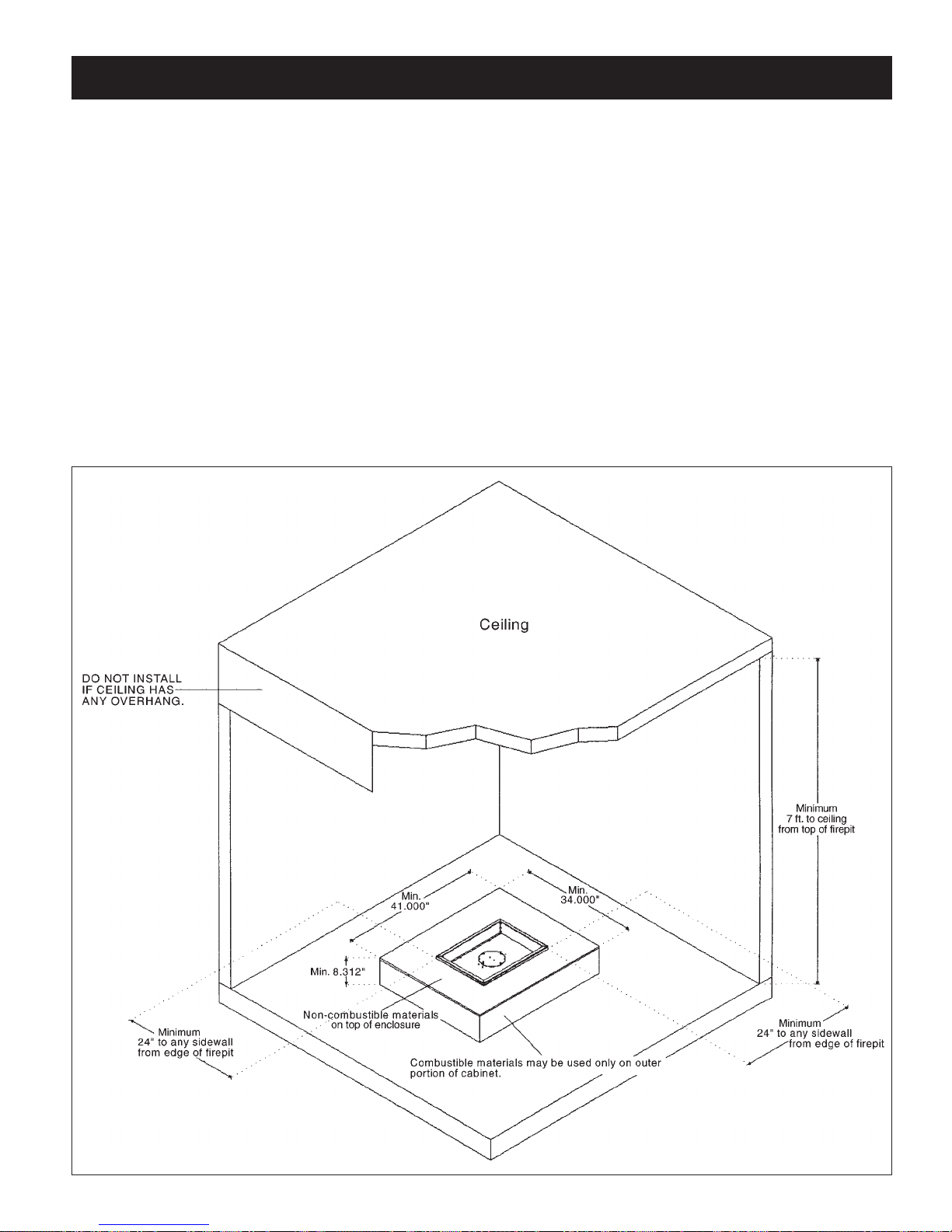
The following clearances to combustible construction
must be maintained: Bottom - 0 inches Sides (all
around)-24 inches (610 mm), and Top-7 feet (2.12 m).
Always keep the appliance area clear and free from
combustible materials, gasoline, and other flammable
vapors and liquids.
Do not locate appliance where it can get excessively wet.
Do not use this appliance if any part has been under
water. Immediately call a qualified service technician to
inspect the unit and to replace any part of the control
system and any gas control which has been underwater.
• Children and adults should be alerted to the
hazards of high surface temperatures and should
stay away to avoid burns or clothing ignition.
• Young children should be carefully supervised
when they are in the area of the appliance.
• Clothing or other flammable materials should not
be hung from the appliance, or placed on or near
the appliance.
• Any guard or other protective device removed for
servicing the appliance must be replaced prior to
operating the appliance.
• Installation and repair should be done by a
qualified service person. The appliance should be
inspected before use and at least annually by a
qualified service person. More frequent cleaning
may be required as necessary. It is imperative the
control compartment, burners and circulating air
passageways of the appliance be kept clean.
• Inspect the fuel supply connection (including the
hose for LP models) before each use of the
appliance.
• If it is evident there is excessive abrasion or wear,
or the hose is cut, it must be replaced prior to the
appliance being put into operation.
• The pressure regulator and hose assembly supplied
with LP models must be used. Replacement
pressure regulators and hose assemblies must be
those specified in this manual.
• The LP gas supply cylinder used with LP models
must be constructed and marked in accordance
with the specifications for LP-gas cylinders of the
U.S. Department of Transportation (DOT).
• Cylinders must be stored outdoors in a well-
ventilated area out of the reach of children.
Disconnected cylinders must have threaded valve
plugs tightly installed and must not be stored in a
building, garage or any other enclosed area.
• Storage of this appliance indoors is permissible
only if it has been disconnected from its fuel supply
(natural gas line or LP gas cylinder).
• The LP gas cylinder supply system must be
arranged for vapor withdraws
• The LP -gas cylinder used must include a collar to
protect the cylinder valve.
• When an LP model is not in use, the LP-gas must
be turned off at the supply cylinder.
1.0 INTRODUCTION
For the state of Massachusetts a T-handle gas shut-off valve
must be used on a gas appliance. This T-handle gas shut-off
valve must be listed and approved by the state of Massachusetts.
This is in reference to the state of Massachusetts state code
CMR238.

5
The log set (LOGC85) and the burner assembly are
shipped separately.
A. Remove the gas log set and burner assembly and
check for damage. DO NOT install damaged
components. The logs are fragile use care when
handling.
B. Place the burner assembly on a flat, stable surface in
an outdoor location such as a patio or a deck. This
location must be adjacent to the gas supply line
(natural gas) or LP-gas supply cylinder. NOTE:
Minimum clearances to combustible construction
must be maintained.
Remember, you must have easy access to the gas
valve control knob AFTER the appliance is installed
and connected to the gas supply.
THE ON/OFF GAS VALVE IS USED TO TURN
THE BURNER ON AND OFF.
C. NATURAL GAS MODELS: Connect the incoming
gas supply line to the on/off gas valve of the
appliance (Figure 1). Make certain ALL gas
connections are tight, turn the on/off valve at the unit
slowly to the on position and use soap water to test
for leaks. DO NOT USE AN OPEN FLAME.
LP-GAS MODELS:
1. Make sure tank valve is in its full off position. (Turn
clockwise to stop).
2. Check tank valve features to ensure it has proper
external mating threads. (Tank Valve Marked: USE
WITH TYPE 1 )
3. Inspect hose shipped with the unit for damage. Never
attempt to use damaged or plugged equipment. See
your local LP Gas Dealer for repairs.
4. After inspecting the LP hose shipped with the unit,
connect the end with the female fitting on the hose to
the male fitting on the on/off gas valve at the end of
the flex tube and make sure it is tight.
5. When connecting regulator assembly to the tank
valve, hand tighten nut clockwise to a positive stop.
DO NOT use a wrench to tighten. Use of a wrench
may damage quick closing coupling nut and result in
a hazardous condition.
6. Locate the hose out of pathways where people may
trip over it or in areas where the hose may be subject
to accidental damage.
7. Open tank valve fully (counter-clockwise). Turn the
on/off valve at the unit slowly to the on position and
use a soapy water solution to check all connections
for leaks before attempting to light the appliance. If a
leak is found, turn tank valve off and do not use the
appliance until repairs can be made by a local LP Gas
Dealer. DO NOT attempt to make repairs yourself.
8. Never attempt to use this appliance or any
components that have been damaged or exposed to
an accidental fire.
D. ENCLOSURES FOR LP-GAS SUPPLY
SYSTEMS.
If you build an enclosure for an LP gas cylinder.
follow these recommended specifications. You must
also follow local codes.
Enclosures for LP-gas supply cylinders shall be
ventilated by openings at the level of the cylinder
valve and at floor level. The effectiveness of the
opening(s) for purposes of ventilation shall be
determined with the LP-gas supply cylinder(s) in
place. This shall be accomplished by one of the
following:
a.
One side of the enclosure shall be completely open; or
b. For an enclosure having four sides, a top and bottom:
1. At least two ventilation openings at cylinder valve
level shall be provided in the side wail, equally sized,
spaced at 180 degrees (3.14 rad), and unobstructed.
Each opening shall have a total free area of not less
than 1/ 2 square inch per pound (3.2 sq. cm/kg) of
stored fuel capacity and not less than a total free area
of 10 square inches (64.5 sq. cm).
2. Ventilation opening(s) shall be provided at floor level
and shall have a total free area of not less than 1/2
square inch per pound (3.2 sq. cm/kg) of stored fuel
capacity and not less than a total free area of 10
square inches (64.5 sq. cm). If ventilation openings at
floor level are in a side wall, there shall be at least two
openings. The bottom of the openings shall be at floor
level and the upper edge no more than 5 inches (127
mm) above the floor. The openings shall be equally
sized, spaced at 180 degrees (3.14 rad) and
unobstructed.
3. Every opening shall have minimum dimensions so as
2.0 ASSEMBLY AND INSTALLATION

6
to permit the entrance of a 1/8-inch (3.2 mm) diameter
rod.
Cylinder valves shall be readily accessible for hand
operation. A door on the enclosure to gain access to the
cylinder valves is acceptable, provided it is non-locking
and can be opened without the use of tools.
There shall be a minimum clearance of 2 inches (50.8
mm) between the lower surface of the floor of the LP-gas
supply cylinder enclosure and the ground.
The design of the enclosure shall be such that (1) the LP-
gas supply cylinder(s) can be connected, disconnected
and the connections inspected and tested outside the
cylinder enclosure; and (2) those connections which
could be disturbed when installing the cylinder(s) in the
enclosure can be leak tested inside the enclosure.
Be certain to mount or set the LP-gas cylinder on a flat
stable surface and retain it to prevent it from tipping.
E. Purge the gas supply line of any trapped air prior to
the first firing of the unit.
WARNING: During the initial purging and
subsequent lightings, NEVER allow gas valve to
remain "OPEN" position without first placing a
burning match on the top of the burner.
F. Place the logs on the burner assembly. See log
placement instructions.
G. Test fire the unit after referring to the SAFETY
INFORMATION and LIGHTING
INSTRUCTIONS found in Section 13 of this
manual.
H. Do not leave the burner on with the cover on.
Figure 1
GAS SPECIFICATIONS
FP2085N FP2085LP
FP2785N FP2785LP
Fuel Natural Gas Liquid Propane
Maximum Supply Pressure 10 IN. W.C./2.47 KPa 13 IN. W.C./3.24 KPa
I. If LP-Gas outdoor firepits are used continuously
after a couple of hours, you could see the possibility
of the flame decreasing in size. If this happens, turn
off the control valve and the tank valve and wait a
couple of hours before lighting again or switch
propane tanks. The propane tank is freezing up due
to the volume of gas being taken out of the tank.
Warning
DO NOT LEAVE FIREPIT
UNATTENDED WHEN IN USE

7
CLEARANCES FOR ROUND FIREPIT (FP2085)
1. The round firepit (FP2085) cannot be built into a
combustible cabinet of any type. Only non-
combustible materials may be placed around firepit.
(eg. bricks, concrete, river rock, etc.)
2. Clearance to combustible side wall is 24” minimum.
Non-combustible walls 14” to side wall.
3. Minimum clearance to any ceiling with no overhang
is to be 7 feet from top of firepit.
4. Clearance to a combustible floor is 0”.
CLEARANCES FOR RECTANGLE FIREPIT (FP2785)
1. The rectangle firepit (FP2785) may be built into a
combustible enclosure. You must maintain minimum
enclosure dimensions of 321/2” x 391/2” I.D. The top
of enclosure must be of a non-combustible material
such as concrete board or wonder board.
2. Clearance to combustible side wall is 24” minimum.
Non-combustible walls 14” to side wall.
3. Minimum clearance to any ceiling with no overhang
is to be 7 feet from top of firepit.
4. Clearance to a combustible floor is 0”.
5. See Section 4.0 for assembly of enclosure.
3.0 INSTALLATION IN COMBUSTIBLE ENCLOSURE

8
1. Minimum size of wood enclosure must be no less
than 32.5” I.D. x 39.5” I.D.
2. Non-combustible material (eg. Wonder Board) for the
top of enclosure must be used, along with using metal
gussets.
3. Non-combustible materials such as tile or brick may
be used to finish on top of Wonder Board. Do not use
any combustible materials to finish top, eg. wood or
plastic products.
4. You must have an opening in the enclosure to have
access to the on/off valve.
4.0 INSTALLING RECTANGLE FIREPIT INTO A WOOD ENCLOSURE

9
1. Using a non-combustible material (eg. Wonder Board)
cut two shields, 1 Large 44” x 30 min. and 1 Small 37”
x 30” min.
2. Mount six 1” non-combustible spacers to wall, this
will maintain a 1” air space behind shields Fig:1Ref:F.
Non-combustible spacer (eg. Metal Bracket, Wonder
Board) should be no wider than 1” and 30” long.
3. Screw non-combustible shield to spacer. Shield must
be placed 1” below top of firepit Fig:2-Ref:D. Inside
corners of shields should not touch combustible wall.
Shield must extend 3” past end of firepit Fig:1-Ref:E.
4. Note: Firepit cabinet or other structures must NOT
obstruct wall shield air space on ends, top or bottom.
If a cabinet is built around firepit, the end face of
cabinet must not extend past bottom face of clearance
shield by more than 1/2” Fig:2-Ref::D.
5.0 INSTALLING WALL CLEARANCE SHIELD
SINGLE CLEARANCE SHIELD
NON-COMBUSTIBLE CORNER CLEARANCE SHIELD
1. Side of unit must be more than 24” from a
combustible wall for a single shield to be used, and
can have a distance of no less than 14” to a wall shield.
2. All specifications as in corner installation must be
used, including shield must extend a minimum of 3”
past sides of firepit Fig:1-Ref:E.

10
6.0 FP2085 FIREPIT ASSEMBLY
Item No. Qty. Part No. Description
1 1 27FP-106 Burner
2 1 20FP-102 Burner Pan
3 1 20FP-101 Frame
4 1 20FP-103 Heat Shield
5 1 27FP-115 Gasket
6 1 27FP-200 Mixing Tube Asm
1 27FP-201
1 4000-208
1 Air Shutter
Item No. Qty. Part No. Description
7 1 1000-255 Orifice
8 1 125 x 375 Flare
9 1 27FP-104 Orifice Retainer
10 2 8-32 x 1.00 Screw
11 2 10-32 x .500 Screw
12 2 10-32 Locknut
13 2
8-18 x .312 TC Screw
14 2
8-18 x .500 DT Screw
15 2
8-32 Locator Pin

11
7.0 FP2785 BURNER ASSEMBLY
Item No. Qty. Part No. Description
1 1 27FP-106 Burner
2 1 27FP-105 Burner Pan
3 1 27FP-115 Gasket
4 1 27FP-200 Mixing Tube Asm
1 27FP-201
1 4000-208
1 Air Shutter
5 1 1000-255 Orifice
Item No. Qty. Part No. Description
6 1 125 x 375 Flare
7 1 27FP-104
Orifice Retainer Brkt
8 2 10-32 x .500 Screw
9 2 8-32 Locator Pin
10 2 8-32 x 1.00 Screw
11 2 10-32 Locknut
12 2
8-18 x .312 TC Screw
13 2
8-18 x .500 TC Screw

12
8.0 FP2785 FIREBOX & COVER ASSEMBLY
Item No. Qty. Part No. Description
1 2 27FP-102 End Frame
2 2 27FP-103 Front & Back Frame
3 2 27FP-107 Leg Assembly
4 4 27FP-108 Corner Bracket
Item No. Qty. Part No. Description
5 1 27FP-113 Cover Body
6 2 27FP-114 Cover End Plate

13
After setting up your model and hooking up the gas connection, make sure that logs are not broken. Identify
the logs using the pictures below and place logs as indicated, lining up with mounting pegs in logs.
9.0 LOG PLACEMENT INSTRUCTIONS
STEP 1 STEP 2
STEP 3
STEP 5
STEP 4
This picture depicts the typical flame pattern of this
burner system.

14
1. The appliance should be inspected before initial use
and inspected and cleaned at least annually by a
qualified field service person.
2. Tampering is DANGEROUS and voids all
warranties. Any component that is found to be faulty,
must be replaced with an approved component.
3.
To obtain proper operation, it is imperative that the
burner flame characteristics are steady, not lifting or
floating. Check the burner flame patterns with Section
9, Step 5.
10.0 OPERATING INSTRUCTIONS
11.0 MAINTENANCE INSTRUCTIONS
4. Periodically remove the logs and examine the burner.
If dirty, clean with a soft brush. Also examine the
area around the burner air shutter. Any dirt or lint in
this area should be removed. This will ensure long
life and trouble free operation. Re-install the logs as
shown in the log placement instructions. When the
appliance is put back in service, check the burner
flame patterns with Section 9, Step 5.
5. Periodically check the hose connecting the LP-gas
cylinder to ensure it is not damaged in any way.
U.L. Listed gas fireplaces are tested and approved for
elevations from 0 to 4,500 feet in Canada and U.S.A.
When installing this fireplace at an elevation above 4,500
feet (in Canada), check with local authorities.
12.0 HIGH ELEVATION INSTALLATION
Consult your local gas utility for assistance in
determining the proper orifice for your location.
Upon completing the gas line connection, a small amount
of air will be in the lines. When first lighting the burner,
it will take a few minutes for the lines to purge
themselves of this air. Once the purging is complete, the
burner will light and operate as indicated in the
instruction manual. Subsequent lighting of the appliance
will not require such purging.
WARNING: Read and follow the Safety and Lighting
Instructions page in this manual and on labels on the
appliance. IF YOU DO NOT FOLLOW THESE
INSTRUCTIONS PRECISELY, A FIRE OR
EXPLOSION MAY RESULT AND YOU MAY BE
SERIOUSLY INJURED!

15
13.0 SAFETY INFORMATION AND LIGHTING INSTRUCTIONS
1. Turn the on/off valve to the off position at the unit
for natural gas unit. For LP unit, turn the on/off
valve to the off position at the unit and then turn the
valve on the LP tank to the off position clockwise.
2. Replace the top cover.
TO TURN OFF GAS APPLIANCE
5. If the burner does not light before the match goes
out, immediately turn the gas to off.
6. Wait at least five (5) minutes to clear out any gas.
If you have unsuccessfully tried to light the burner,
wait longer. Then smell for gas, including near the
floor. If you smell gas, STOP! Follow “B” in the
safety information above. If you don’t smell gas,
repeat step 4.
1. STOP! Read the safety information above.
2. Remove the top cover.
3. Find the manual gas control valve.
4. Place a burning match on top of burner in the
middle where ports are present. DO NOT HOLD
THE MATCH IN HAND. For Natural Gas unit
turn on the on/off valve slowly at the unit. For LP
unit turn the valve on the LP tank counter-
clockwise all the way and then turn on the on/off
valve slowly at the unit.
• If you cannot reach your gas supplier, call the fire
department.
C. Use only your hand to turn the gas control knob or
valve. Never use tools. If the valve will not turn by
hand, don’t try to repair it, call a qualified service
technician. Force or attempted repair may result in
a fire or explosion.
D. Do not use this appliance if any part has been
underwater. Immediately call a qualified service
technician to inspect the appliance, and to replace
any part which has been underwater.
A. This appliance must be lit by hand. When lighting,
follow these instructions exactly.
B. Before LIGHTING, smell all around the appliance
area for gas. Be sure to smell next to the floor,
because some gas is heavier than air and will settle
on the floor.
WHAT TO DO IF YOU SMELL GAS
• Do not try to light any appliance.
• Do not touch any electric switch; do not use any phone
in your building.
• Immediately call your gas supplier from a neighbours
phone. Follow the gas suppliers instructions.
WARNING: If you do not follow these instructions exactly, a fire or explosion may result
causing property damage, personal injury or loss of life.
FOR YOUR SAFETY READ BEFORE LIGHTING
LIGHTING INSTRUCTIONS

16
Product Numbers
Product
Number Description
KINGSMAN FIRE PITS:
Listed for Canada and USA
FP2085N Round 20” Diameter - 77,500 BTU - Natural Gas
FP2085LP Round 20” Diameter - 82,000 BTU - Liquid Propane
FP20COV Cover for Round Fire Pit
FP2785N Rectangular 27” x 20” - 77,500 BTU - Natural Gas c/w Cover
FP2785LP Rectangular 27” x 20” - 82,000 BTU - Liquid Propane c/w Cover
LOG SET: (Required for each Fire Pit)
LOGC85 Log Set - Four piece Cast oak
KINGSMAN FIRE PITS REPLACEMENT PARTS
Part
Number Description
27FP-900FF LP REG & 5FT HOSE (I4T60GRQC)
27FP-901FF MANOMETER VALVE (BVTM5042-6)
27FP-902FF SS GAS CONNECTOR 16” (ACS-375-16)
27FP-903FF SS GAS CONNECTOR 22” (ACS-375-22)
27FP-P904FF BRASS CONNECTOR 48-6A
1000-255 BRASS ORIFICE
27FP-115 GASKET
When requesting service or replacement parts for your fireplace, please provide model number and serial number.
All parts listed in this manual may be ordered from an authorized dealer.
14.0 REPLACEMENT PARTS - FP2085/FP2785

17
Kingsman Industries Gas Firepit – Limited Warranty
Save this certificate. It gives you specific legal rights, and you may also have other rights which may vary from state
to state.
In the event your unit needs servicing contact your dealer or contractor who installed or service your unit. When requesting
service, please have the model and serial number from each unit readily available. If your dealer needs assistance, the
distributor is available for support and we, in turn support the distributor's efforts.
Fill in the installation date and model and serial numbers of the unit in the space provided below and retain this limited
warranty for your files.
GENERAL TERMS
This limited warranty applies only while the unit remains at the site of the original installation and only if the unit is
installed inside the continental United States, Alaska, Hawaii and Canada. The warranty applies only if the unit is installed
and operated in accordance with the printed instructions and in compliance with applicable installation, building codes and
good trade practices.
During the first year after installation, we will provide a replacement for any component part of your unit found to be
defective in materials or workmanship. . All replacement parts will he warranted for the unused portion of the component's
warranty. The part to be replaced must be returned to our distributor in exchange for the replacement part.
In lieu of providing a replacement part, we may, at our option, provide the distributor's component purchase price from us or
a credit equal to the distributor’s component purchase price from us toward the purchase of any new unit which we
distribute. If a credit is given in lieu of a replacement part, the rating plate from the unit being replace must be submitted on
a warranty claim and the unit being replaced must be made available to our distributor for disposition.
In establishing the date of installation for any purpose including determination of the starting date for the term of this limited
warranty, reasonable proof of the original installation date must be presented*, otherwise the effective date will be based
upon the date of manufacture plus thirty (30) days.
Any labor, material, freight and/or handling charges associated with any repair or replacement pursuant to this limited
warranty will be your responsibility. In this warranty the word "installation" means original installation.
We will not be responsible for and you the user will pay for: (a) damages caused by accident, abuse, negligence, misuse,
riot. fire, flood, or Acts of God (b) damages caused by operating the unit where there is a corrosive atmosphere containing
chlorine, fluorine, or any other damaging chemicals (other than in a normal residential environment) (c) damages caused by
any unauthorized alteration or repair of the unit affecting its stability or performance (d) damages caused by improper
matching or application of the unit or the unit's components (e) damages caused by failing to provide proper maintenance
and service to the unit (f) any expenses incurred for erecting disconnecting or dismantling the unit (g) parts or supplies used
in connection with service or maintenance (h) damage repairs, inoperation or inefficiency resulting from faulty installation or
application (i) electricity or fuel costs or any increase in electricity or fuel cost whatsoever including additional or unusual
use of supplemental electric heat.
We shall not be liable for any incidental, consequential, or special damages or expenses in connection with any use or failure
of this unit. We have not made and do not make any representation or warranty of fitness for a particular use or purpose and
there is no implied condition of fitness for a particular use or purpose. We make no express warranties except as stated in
this limited warranty. No one is authorized to change this limited warranty or to create for us any other obligation or liability
in connections with this unit. Any implied warranties shall last for one year after the original installation. Some states and
provinces do not allow the exclusion or limitation of incidental or consequential damages or do not allow limitations on how
long an implied Warranty or condition lasts so the above limitations or exclusions may not apply to you. The provisions of
this limited warranty are in additions to and not a modification of or subtraction from an statutory warranties and other rights
and remedies provided by law.
Model No.: _______________________________________ Serial No.: _______________________________________
Date Installed: _____________________________________
*To receive advantage of your warranty, you must retain the original records that can establish the installation date of your unit.
Other manuals for FP2085
1
This manual suits for next models
4
Table of contents
Other Kingsman Outdoor Fireplace manuals