KIOSHI INTERACTIVE PIANO SILENT SYSTEM User manual

Contents
Product introduction
Tools to use
Piano disassembly
Mute Rail installation
- Step 1: Remove action
- Step 2: Assembly of mute rail
- Step 3: Preparation of mute rail
- Step 4: Installation of mute rail and mute lever
- Step 5: Installation of action
Sensor Rail installation
- Step 1: Disassembly of keys and attachment of reflective stickers
- Step 2: Assembly and placement of sensor rail
- Step 3: installation of sensor rail
- Step 4: Installation of pedal sensor
Control Box installation
- Step 1: Installation of control box
- Step 2: Key calibration
- Troubleshooting
- Step 3: Installation of the piano

Product
introduction
Kioshi Interactive Piano Silent System is an
intelligent electronic device that allows a
traditional piano to be muted, allowing the
player to use the interactive functions and/or
play with headphones.
Five parts of Kioshi:
1. Control box
2. Sensor rail
3. Mute rail
4. Pedal sensors
5. Accessories: Mute lever, signal cables, mute rail
kit, power adapter, sensor rail holder, spring
screw kit, and pedal bracket
Three key stages of installation:
1. Mute rail
2. Sensor rail and pedal sensors
3. Control box and calibration
3

fig. 1.1: Extra brackets
fig. 1.2: Position the
bracket in the middle of the
mute rail
fig. 1.4: Installation of hook
of mute rail
fig. 1.3: Install support rod
at both sides of mute rail
STEP 2: PREPARATION OF MUTE RAIL
1. Prepare the mute rail: If your action has a mounting
option in the middle, attach the extra bracket (fig. 1.1) in
the middle of the action (fig. 1.2).
2. Install the threaded rods at both sides. Screw them in by
hand (fig. 1.3) and tighten them with a flat-head
screwdriver.
3. Install the hook of the mute rail. Lay the mute rail with
the white strip downwards. Now position the hook
downwards on the fabric (fig. 1.4) and mount the hook
to the mute rail with the screws.
7

4. Install the brackets at both ends:
•Slide the treble side bracket (fig. 1.5) onto the left
threaded rod. Keep the concaved surface facing
outwards. Fix the bracket with an M5 screw (included).
•Slide the bass side bracket (L-type) (fig. 1.6) onto the
threaded rod on the right side (hook side) of the mute
rail. Fix the bracket with an M5 screw (included).
fig. 1.5: Treble side bracket fig. 1.6: Bass side bracket (L-type)
8

STEP 3: ASSEMBLY OF MUTE RAIL
1. If you have two mounting points: mount the mute rail
onto the action with M5 screws (included). Mount them
as low as possible (fig. 1.7). Confirm all hammer shanks
can be stopped (fig. 1.8), and adjust to the left or right if
needed.
2. If you have three mounting points (also a middle
bracket): mount all 3 points with the M5 screws. At the
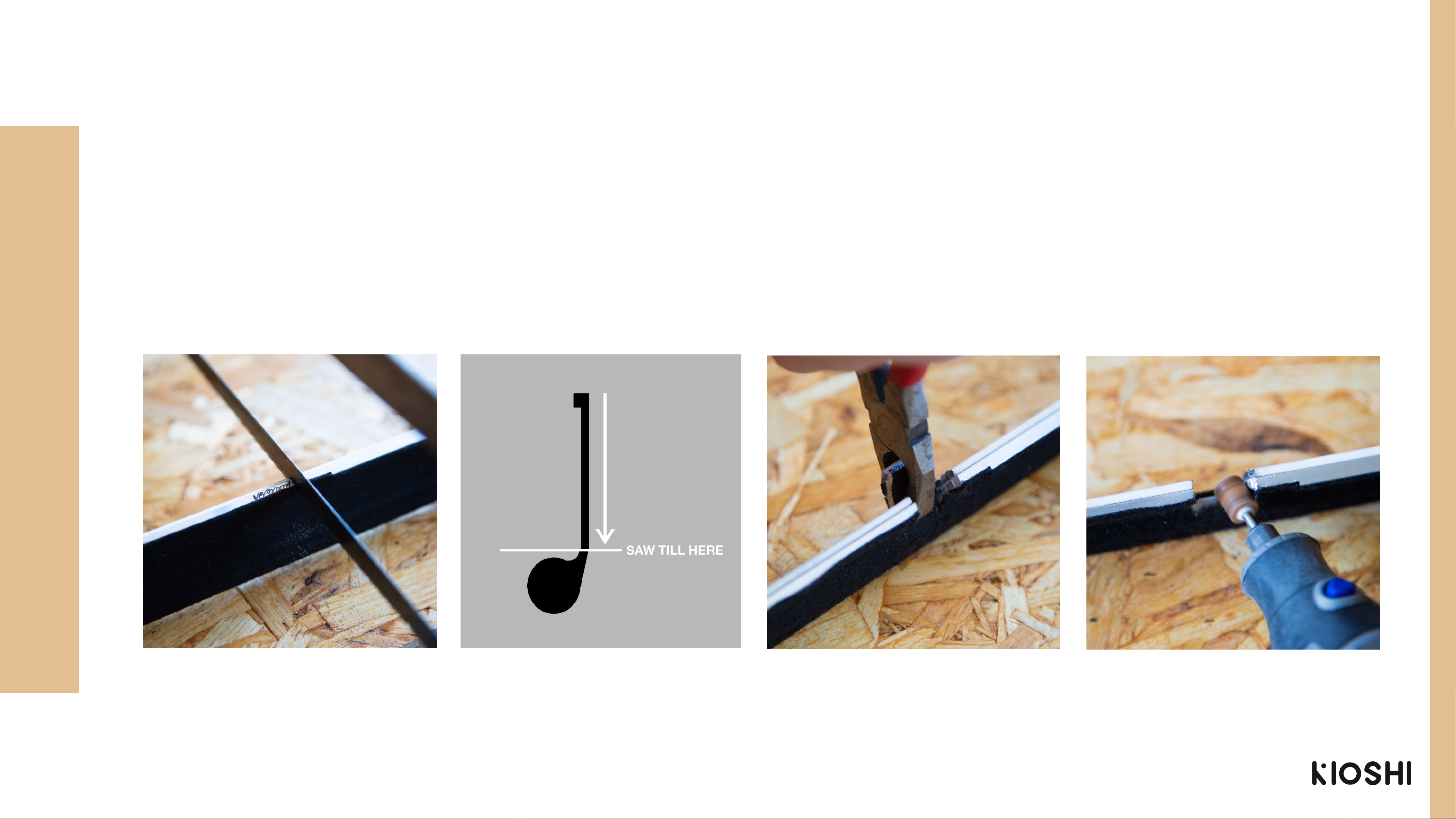
middle bracket, mark the position for cutting (fig. 1.9), so
that the mute rail can move freely back and forth.
Reserve 5mm width on both left and right side, and
mark the cutting position. After clear marking,
disassemble the mute rail.
fig. 1.7: Installation of
mute rail
fig. 1.9: Mark cutting/
sawing position for
middle bracket
fig. 1.8: Confirm that all
hammer shanks can be
stopped
9

3. At the marked spot, make two incisions with a metal saw, leaving the bottom intact (fig. 1.10).
Make sure your incisions are deep enough, and reach the bottom part (fig. 1.11). Remove the
sawn piece with pliers. (fig. 1.12)
4. After sawing, make sure you file any sharp edges. (fig. 1.13)
fig 1.11: Sideview mute tail, cut
deep enough until the thick
rounded part.
fig.1.10: Cutting of white glue strip
at market position
fig. 1.12: Remove cutout with
pliers
fig. 1.13: file the sharp edges with
a multitool or file
10

STEP 4: INSTALLATION OF MUTE RAIL AND
MUTE LEVER
1. Fix the mute rail onto the action like before. (fig. 1.14,
1.15 and 1.16).
•Horizontal: Make sure all hammer shanks can be
stopped.
•Vertical: Brackets at both sides should be mounted as low
as possible.
•Depth: Sometimes the mute rail is too close to the
hammer shanks. To adjust this distance, pads can be
inserted between the action bracket and the fixation.
These pads are included in the parts bag.
fig. 1.14: Fixing of mute
rail
fig. 1.15: Make sure all
hammer shanks can be
stopped
fig. 1.16: Height check:
Hammers cannot touch
the mute rail.
11

3. Take out the mute lever and brake cable. Check that the position of the lock buckle is 48mm from
the end of the cable shell (fig. 1.20) when the mute lever is closed (lever in a 90° angle). Tighten the
lock buckle. Hang the lock buckle in the hook opening while keeping the cable shell in the circular
slot of the L-bracket (fig. 1.21).
Now use the adjustment bus (fig. 1.22) to fine tune the tension on the cable. Make sure all hammer
shanks are properly blocked when the mute lever is pulled, and all hammer shanks can move freely
when the mute lever is in neutral position. If the range of the adjustment bus is not sufficient, adjust
the position of the lock buckle.
fig. 1.21: Cable shell in L-
bracket
fig. 1.20: Distance of the lock buckle fig. 1.22: Adjustment bus
13

STEP 5: INSTALLATION OF ACTION
1. Remove the brake cable of the mute lever and install
the action back into the piano.
2. Guide the brake cable from under the piano upwards
through the bottom of the keybed, and attach the cable
to the hook and L-bracket as before. Check if the action
functions as normal, and if the mute rail responds to the
mute lever as before. Adjust where needed.
3. Install the lever box at the lower left underside of the key
bed with the supplied screws. Install the lever box in a
position, so that the lever is flush with the piano when
pulled (fig. 1.25).
fig. 1.23: Micro
adjustment of brake cable
fig. 1.24: Lever box
fig. 1.25: The mute lever is flush with the front of
the piano when pulled
14

2. Take the 4 sensor rail brackets and spring screws; place the springs onto the stud bolt on the
bottom side of the brackets (Fig. 2.1) and attach the 4 brackets to the sensor rail (Fig. 2.2).
3. Two sensor rail brackets are placed around the wooden bracket at both sides of the keyboard
frame, while the two middle holders are placed where two circuit boards connect. As a result, the
four sensor rail brackets are evenly distributed onto the sensor rail.
4. Put the sensor rail onto the key bed: The side with LED’s should be pointed towards yourself.
Meanwhile, insert the flat keyboard signal cable on the right side of the sensor rail.
fig. 2.2: Slide the brackets onto the sensor
rail
fig. 2.3: Distribute the brackets evenlyfig. 2.1: The sensor rail brackets and springs
16

STEP 2: INSTALLATION OF SENSOR RAIL
Adjust the position for installing the sensor rail.
Horizontal position: Find 4 black keys near the sensor rail brackets and put
them onto the keyboard (fig. 2.5). Align the sensor LED's sideways with the 4
black keys. Make sure the corresponding LED's are under the black keys and
precisely in the middle. Double check the four black keys with a good look from
above. After adjustment, lock the white grub screws. At last, install all the other
keys, and the keyboard sensor has been installed completely.
Vertical position: The goal is to get a 4mm distance from the top of the sensor
LED to the bottom of the pressed down key. For this, screw in the 8 spring
screws until the bracket is touching the key bed. Now push the black key down
and raise the height of the spring screw again, until proper distance is met. (fig.
2.6). Check the height of the neighbouring white keys. If they don’t have same
distance to the sensor as the black keys, the piano needs regulation before you
can continue with the initialisation of Kioshi.
17

1. Take out the two types of silver reflective stickers (thick and thin) (fig. 2.8) and attach them to the
underside of the keys (fig. 2.9). Use the thick stickers for the white keys and the thin stickers for the
black keys. Make sure the stickers are centred above the sensor LED's (fig. 2.10). Excessive reflective
stickers can be put aside for future use.
•2mm thickened reflective stickers are only used for white keys; the two widest reflective stickers are for key 1 and key 88.
•Make sure that the stickers are smooth, clean and free from wrinkles or stains.
Note:
fig. 2.7: Disassembly of keys in step 1 fig. 2.8: Reflective stickers (think and
thin)
fig. 2.9: Position of the reflective stickers
STEP 3: ATTACHMENT OF REFLECTIVE STICKERS
19

Sensor LED
Sensor rail
Reflective sticker
Wrong placement
Right placement
fig. 2.10: Sticker placement
4. Double check the position of the stickers. Make sure the reflective sticker is positioned and centered
right above the sensor LED, and NOT positioned and centered over the sensor rail. Wrong placement of
the reflective stickers can result in dysfunctioning of keys.
20
Other manuals for INTERACTIVE PIANO SILENT SYSTEM
1
Table of contents