KITO TS Series Operator's manual

OM-TSLZZZ-CEE-01
Supplement Manual
OWNER’S (OPERATOR’S) MANUAL
AND SAFETY INSTRUCTIONS
FOR KITO GEARED TROLLEY
TSSERIES (Model TSB)
For WLL 7.5t to 30t
This supplement Manual includes information only for larger WLL trolleys.
ALWAYS use this Manual in combination with the original Manual (“OWNER’S
(OPERATOR’S) MANUAL AND SAFETY INSTRUCTIONS (Bulletin NO. OM-TSZZZZ-CEE-01)”).
ALWAYS SAVE THIS BOOK FOR FUTURE REFERENCE.
Original Instruction
Issued January 2010. Revised May, 2016 (revision 05)

CONTENTS
Remarks : (1) Information written in bold letters is included in this manual.
(2) For information marked with a ☆, refer to the “OWNER’S (OPERATOR’S) MANUAL AND
SAFETY INSTRUCTIONS (OM-TSZZZZ-CEE-01).”
1. DEFINITIONS ................................................................................................................................................ ☆
2. INTENDED PURPOSE .................................................................................................................................. ☆
3. BEFORE USE................................................................................................................................................. ☆
3.1 Safety summary ..................................................................................................................................... ☆
3.2 Safety instructions ................................................................................................................................... ☆
4. MAIN SPECIFICATION...................................................................................................................... 1
5. INSTALLATION.................................................................................................................................. 2
5.1 Coupling with M3 series manual chain hoists....................................................................... 2
5.2 Coupling with ES or ER series electric chain hoists............................................................. 3
5.3 Adjusting trolley width before installation ............................................................................. 5
5.4 Installation of trolley onto beam.............................................................................................. 6
5.5 Installation of stopper onto traversing beam ........................................................................................... ☆
5.6 Check points after installation................................................................................................................. ☆
6. OPERATION .................................................................................................................................................. ☆
6.1 Intended purpose of trolley operation...................................................................................................... ☆
6.2 Safety working environment ................................................................................................................... ☆
6.3 Operation................................................................................................................................................. ☆
6.4 Trolley storage......................................................................................................................................... ☆
7. INSPECTION.................................................................................................................................................. ☆
7.1 Outline..................................................................................................................................................... ☆
7.2 Daily inspection....................................................................................................................................... ☆
7.3 Periodic inspection ................................................................................................................... 8
8. MAINTENANCE............................................................................................................................................ ☆
8.1 Lubrication .............................................................................................................................................. ☆
8.2 Overhaul and assembly............................................................................................................ 9
9. OPTIONAL BUFFER..................................................................................................................................... ☆
9.1 Buffer....................................................................................................................................................... ☆
10. CONFORMITY DECLARATION ................................................................................................................. ☆
11. WARRANTY.................................................................................................................................................. ☆
12. PARTS LIST..................................................................................................................................... 12

—1—
4. MAIN SPECIFICATIONS
Code WLL
(t) Rail width range B (mm)
Minimum radius
for curve (mm) Net weight (kg) Hand chain folded
length (m) a max. (mm)
M3
combined (C) ES
combined (E) Standard Option W30 (C) (E) (C) (E) (C) (E)
TSG075C TSG075E 7.5
150 to 220 221 to 305
3000 112 121 4.0 3.5 439 549
TSG100C TSG100E 10 3000 112 116 4.0 3.5 439 549
TSG150C TSG150E 15 265 235 4.5 4.0 439 549
TSG200C TSG200E 20 265 235 4.5 4.0 439 549
TSG300C — 30 175, 190 — 470 — 5.0 — 543 —
Code WLL
(t) b (mm) d (mm) e (mm) f (m) g (mm) h (mm) k (mm) l (mm) m (mm)
(C) (E) (C) (E) (C) (E) (C) (E)
TSG075C TSG075E 7.5 523 633 492 178 288 3.7 3.2 170 196.5 φ70 — 230
TSG100C TSG100E 10 523 633 492 178 288 3.7 3.2 170 196.5 φ70 — 230
TSG150C TSG150E 15 576 796 1012 178 288 4.2 3.7 170 196.5 φ70 520 230
TSG200C TSG200E 20 576 796 1012 178 288 4.2 3.7 170 196.5 φ70 520 230
TSG300C — 30 790 — 1160 300 — 4.7 — 197 233 φ70 600 235
Remarks : (1) The maximum 300mm rail width are available as option. (W30 range)
(2) Net weight is when flange width is in standard.
(3) Dimension “a” is when flange width is adjusted to the maximum of the standard range.
(4) Dimension “b” is when flange width is in standard range.
(5) Dimension “f” is hand chain in folded.
Allowable ambient conditions;
Operation temperature: -20C to +60C: (–20°C to + 40°C for the use with an electric chain hoist)
Operation humidity: up to 100%
Note:
- Install the trolley at the level an operator is able to operate the hand chain on the ground.
- If the adjustment of the bottom at the hand chain between 500mm and 1000mm from the ground is required,
consult KITO.
7.5t and 10t
15t, 20t and
30t
—2—
5. INSTALLATION
5.1 Coupling with M3 series manual chain hoists
(1) This series of the geared trolley covers from 7.5t to 30t WLL and allows to couple with the same range of
M3 series manual chain hoist.
(2) The coupling is realized by a manner where a suspension shaft of a trolley suspends a top hook of a hoist
directly.
(3) In cases of 7.5t and 10t couplings, the top hook of a hoist is suspended by single suspension shaft
connecting a couple of side plates as illustrated in the previous section of main specification.
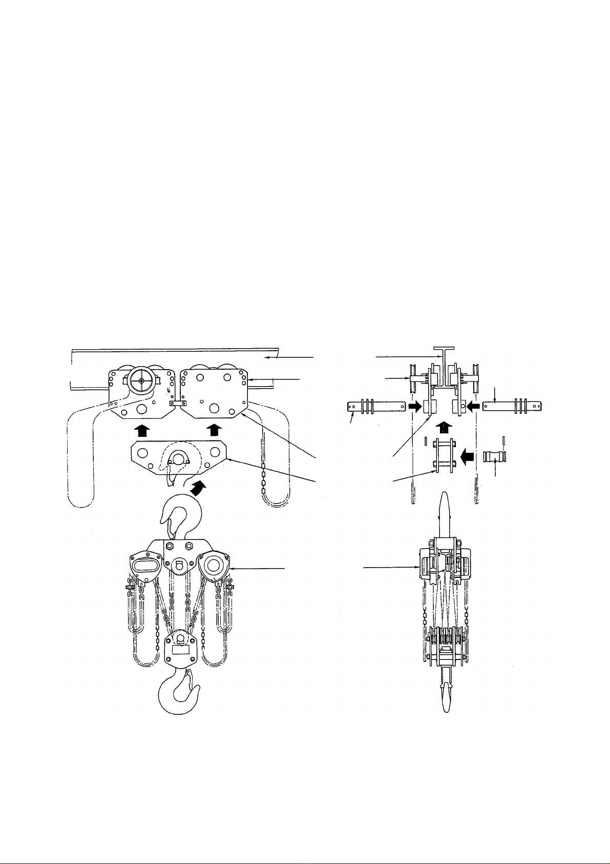
And in cases of 15t, 20t and 30t couplings, the top hook of a hoist is suspended by a particular suspension
shaft which is connected to two pairs of side plates through a couple of suspension plates as illustrated
below Fig. 5-1.
(4) See section 5.3 to adjust the trolley width to an expected rail width, and see section 5.4 to install the
trolley onto the traversing rail.
Fig. 5-1 Connecting M3 hoist to TSG trolley (Example of 15t, 20t and 30t)
TSG trolley Traversing rail
Traversing unit
Suspension
shaft
Suspension
shaft
Trolley sde plate
Suspension plate Suspension shaft
for top hook
Top hook
Lifting unit
—3—
5.2 Coupling with ES, ER series electric chain hoists
(1) This series of the geared trolley covers from 7.5t to 20t WLL and allow to couple with the same range of
ES, ER series electric chain hoist.
(2) The coupling is realized by means of not a top hook like M3 but a couple of top suspension plates which
is to be connected to trolley side plates by suspension shaft.
(3) In case of 7.5t and 10t couplings, an electric chain hoist consisting of a pair of lifting units is suspended
by single suspension shaft because a trolley consists of a couple of side plates.
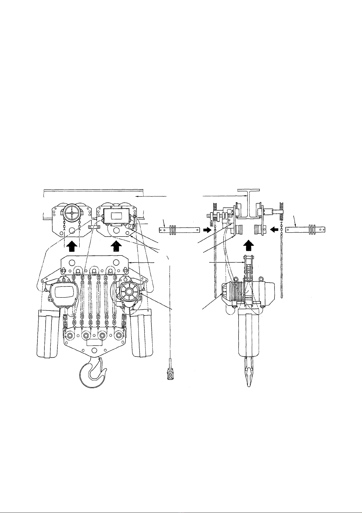
And in cases of 15t and 20t couplings, an electric chain hoist also consisting of a pair of lifting units is
suspended by a couple of suspension shafts because a trolley consists of two couples of side plates as
illustrated below Fig. 5-2 or Fig. 5-3.
(4) See section 5.3 to adjust the trolley to harmonize with an expected rail width, and see section 5.4 to install
the trolley on to the traversing rail.
Fig.5-2 Connecting ES hoist to TSG trolley (Example of 15t or 20t)
Geared trolley Traversing rail
Traversing
unit
Suspension
shaft Suspension
shaft
Trolley side plate
Top suspension plate
Lifting unit
—4—
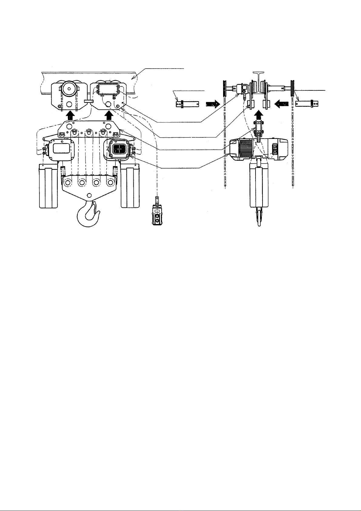
Fig. 5-3 Connecting ER hoist to TSG trolley (Example of 15t or 20t)
Geared trolley
Traversing rail
Traversing unit
Suspension
shaft
Suspension
shaft
Trolley side plate
Top suspension plate
Lifting unit

—5—
5.3 Adjustment of trolley width before installation
Before installation, NEVER fail to make the following adjustment for a proper clearance between the
traversing rail flange and track wheel flange.
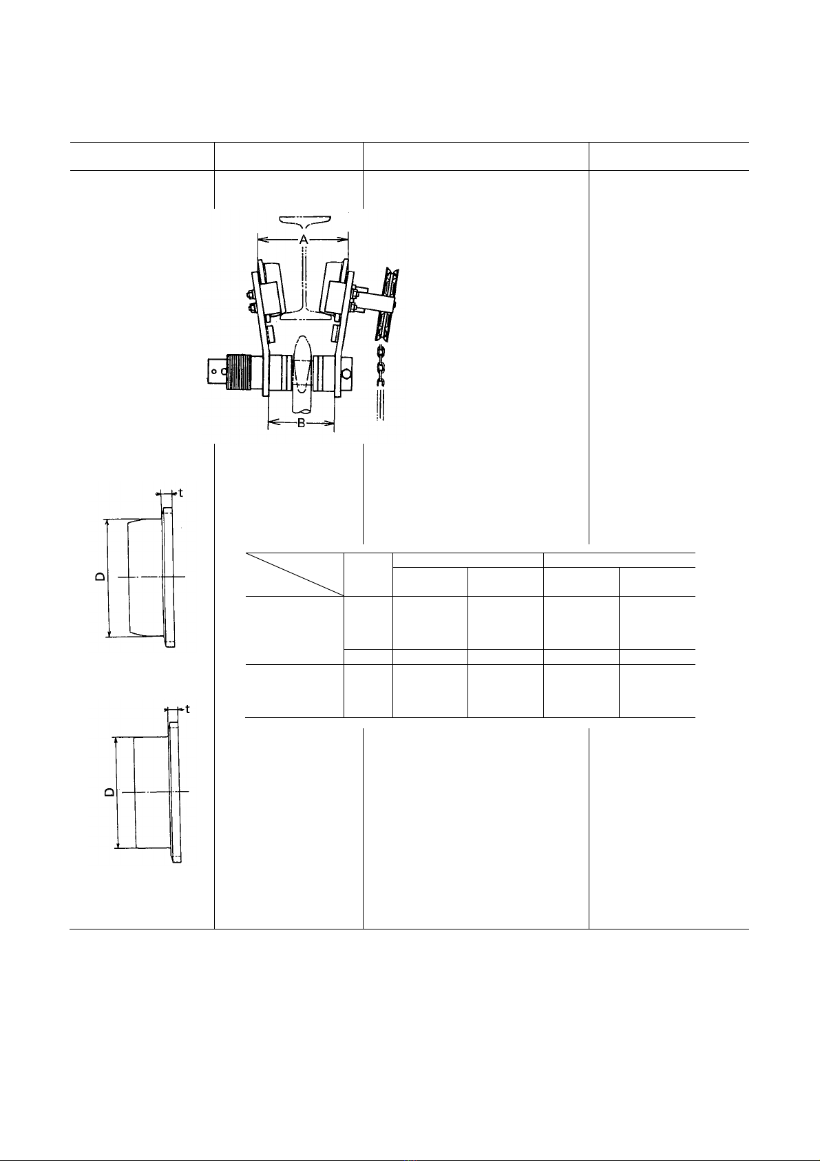
5.3.1 Adjusting “A”
When the side plates S and G are spread fully outside, the proper distance between them should be so that
the dimension “A” becomes approximately 4mm wider than the dimension “B”. (See figure below.)
Make adjustment by adding or subtracting the inner or outer spacers irrespective of the numbers tabulated
in Table 5-1.
5.3.2 Adjusting spacers arrangement
The Table 5-1 has been prepared for the purpose to inform proper arrangement of adjusting spacers
consisting of thin, thick and fixing spacers to applicable range and considerable size of traversing rail. .
5.3.3 Note on 15t, 20t and 30t trolleys
Because two traversing units are combined in a 15t, 20t and 30t trolley, NEVER fail to adjust both units
correctly in the same way.
ALWAYS insert securely the split pin into the shaft stopper pin to avoid coming off the suspension shaft.
Note; Either trolley to be mounted on tapered flange rail
or trolley to be mounted on flat flange rail is
available. Please make sure that purchased product
has appropriate wheels that match your rail type.
Flat flange wheel Tapered flange wheel
WARNING

—6—
Table 5-1 Adjusting spacers arrangement on suspension shaft
Number of adjusting spacers
Beam flange width
(mm)
149
150 153 155 160 163 170 175 178 180
181 184
185 200 203 215 220 229 232 250 254 257 260 264 267 279 283 286 289 295 298 300 302 305
WLL
(T)
Spacers
7.5
10
Thin spacer
Inner 1+1 1+2 1+2 2+3 3+3 4+4 1+1 1+2 2+2 2+3 1+1 1+2 3+3 4+4 1+1 1+2 4+4 1+1 5+1 5+2 2+3 3+3 1+1 1+2 2+2 2+3 3+0 4+0 4+0 4+1 5+1
Outer 6 5 5 3 2 0 6 5 4 3 6 5 2 0 6 5 0 6 2 1 3 2 6 5 4 3 5 4 4 3 2
Thick spacer
Inner 2+2 2+2 2+2 2+2 2+2 2+2 3+3 3+3 3+3 3+3 4+4 4+4 4+4 4+4 2+2 2+2 2+2 3+3 2+3 2+3 3+3 3+3 4+4 4+4 4+4 4+4 4+5 4+5 4+5 4+5 4+5
Outer 4 4 4 4 4 4 2 2 2 2 0 0 0 0 5 5 5 3 4 4 3 3 1 1 1 1 0 0 0 0 0
Fixing spacer
Inner 2 2 2 2 2 2 2 2 2 2 2 2 2 2 2 2 2
15
20
Thin spacer
Inner 0 1+0 1+1 1+2 2+2 3+3 0 1+0 1+1 1+2 4+0 4+1 6+2 7+3 1+1 1+2 4+4 1+1 1+2 2+2 2+3 3+3 1+1 1+2 2+2 2+3 3+4 4+4 4+0 4+1 5+1
Outer 10 9 8 7 6 4 10 9 8 7 6 5 2 0 6 5 0 6 5 4 3 2 6 5 4 3 1 0 4 3 2
Thick spacer
Inner 0 0 0 0 0 0 1+1 1+1 1+1 1+1 1+2 1+2 1+2 1+2 3+3 3+3 3+3 4+4 4+4 4+4 4+4 4+4 5+5 5+5 5+5 5+5 5+5 5+5 5+6 5+6 5+6
Outer 3 3 3 3 3 3 1 1 1 1 0 0 0 0 5 5 5 3 3 3 3 3 1 1 1 1 1 1 0 0 0
Fixing spacer
Inner
30
175 190
Inner 0 1+1
Outer 2 0
5.4 Installing trolley onto traversing rail
5.4.1 Installing from the rail end
In case that the trolley can be installed by entering from the rail end as completed condition coupled with a
hoist;
(1) remove the stopper at the end of the rail,
(2) enter the completed (having adjusted to meet the rail width and assembled) trolley from the rail end
along the rail flange, and
(3) fix the stopper to the rail end surely.
5.4.2 Installing separately
In case that the trolley can not be installed by entering from the rail end, install it separately by dividing into
side plate S, side plate G and hoist unit as the following Fig. 5-5 or Fig. 5-6.
Note: 1) Take note the numbers on spacers of inner side as follows.
Example 0 + 1 Number on side plate S
Number on side plate G
2) Adjustment of trolley width
Refer to 5.3 on page 5.
Adjustment the dimensions by appropriately increasing or decreasing the number of
inner or outer adjusting spacers, without strictly adhering to the number of adjusting
spacers shown in the above table.

—7—
NEVER try to separate a trolley side plates S and G if it is coupled with a hoist when they are suspended on the
rail for installation.
(1) Separate the hoist from the trolley, if they are coupled.
(2) Mount the trolley onto the rail;
(a) remove the shaft stopper pin from the suspension shaft, and remove the side plate S, spacers and
top hook or suspension plate,
(b) mount the track wheels of the side plate G onto the rail flange,
(c) assemble the spacers, top hook or suspension plate, other spacers and side plate S onto the
suspension shaft,
(d) push in the side plate S with mounting the track wheels onto the other side of the rail flange,
(e) insert the shaft stopper pin into the suspension shaft securing it with a split pin,
(f) bend correctly both branches of the split pin after insert, and
(g) connect the hoist to the trolley.
Fig. 5-5 TSG trolley for M3 manual
chain hoist
Suspension
shaft
Suspension
shaft
Track
wheel
Split pin
Split pin
Shaft
stopper pin
(bolt)
Slotted nut
Adjusting
spacers
Side plate G
Side plate S
Adjusting
spacers
Shaft
stopper pin
Hand chain
Key plate
Suspension shaft
for top hook
Suspension plate Key plate
Fig. 5-6 TSG trolley for ES
electric chain hoist
Suspension
shaft
Suspension
shaft
Track
wheel
Split pin
Split pin
Shaft
stopper pin
(Bolt)
Slotted nut
Adjusting
spacers
Side plate G
Side plate S
Adjusting
spacers
Shaft
stopper pin
Hand chain
DANGER
—8—
7.3 Periodic inspection
Item Inspection method Discard limit/criteria Remedy
2. Side plate
deformation Check with calipers. The difference of dimension “A” and
“B” should not exceed 2mm. If the difference exceeds
2mm, replace it with a
new one.
3. Track wheel wear
Track wheel for
tapered rail flange
Track wheel for flat
rail flange
Check visually or use
calipers as needed. Wear of flange tread should not be
less than the limits on the table below. Replace it with a new one
if it is less than the limit.
Track
wheel
WLL
(t)
Tread diameter: D (mm) Flange thickness: t (mm)
Standard Limit Standard Limit
For tapered rail
flange
7.5
10
15
20
φ155 φ148 13 9
30 φ175 φ167 22 15
For flat rail
flange
7.5
10
15
20
φ147 φ140 13 9
—9—
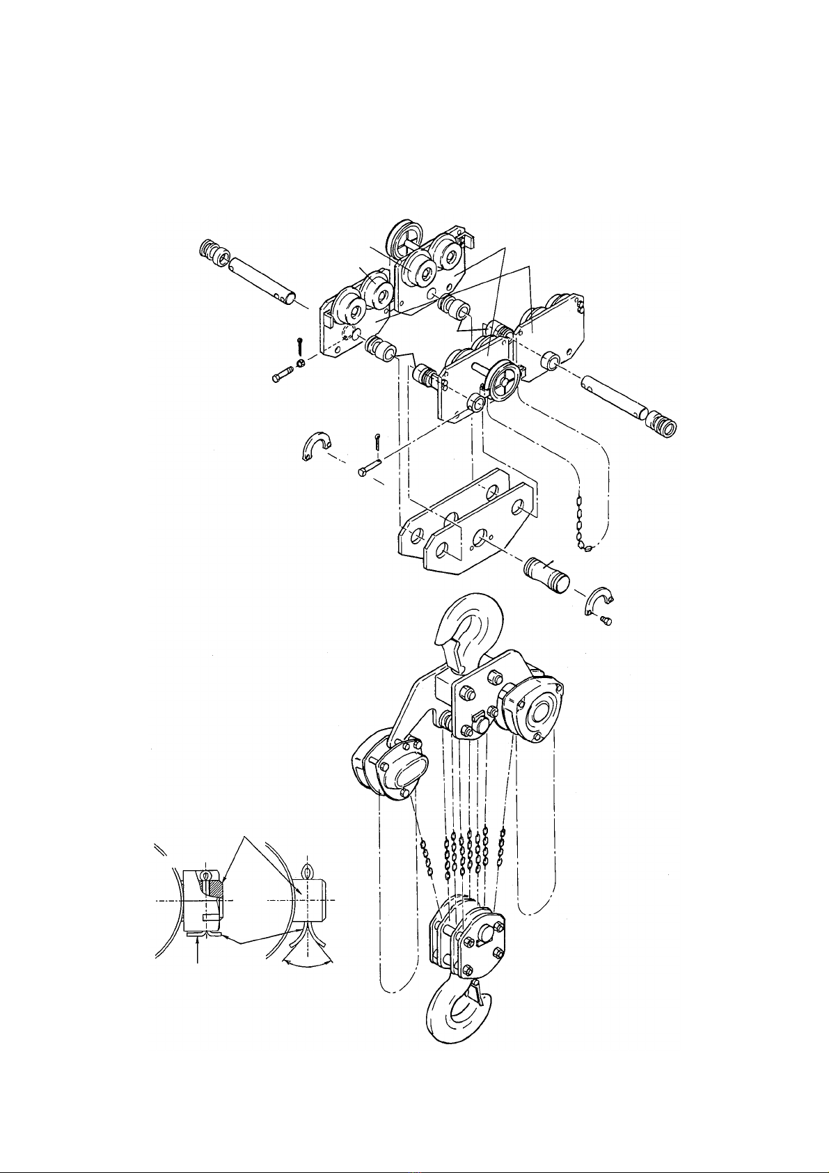
8.2 Overhaul and assembly
Overhaul and assembly should be performed with reference to the following Fig. 8-1 or 8-3
Fig. 8-1 Trolley parts arrangement for M3 hoist
Suspension
shaft
Suspension
shaft
Split pin
Split pin
Shaft
stopper pin
(Bolt)
Slotted nut
Adjusting
spacers
Side plate G
Side plate S
Adjusting
spacers
Shaft
stopper pin Hand chain
Key plate
Suspension shaft for top hook
Suspension plate
Key plate
Hand wheel
Track wheel G
Track wheel S
Top hook
M3 manual chain hoist
Shaft stopper pin
Slotted nut
Suspension
shaft
Split pin
Split pin is
required to be
bent fully.
Required to be wider
than 70°
—10 —
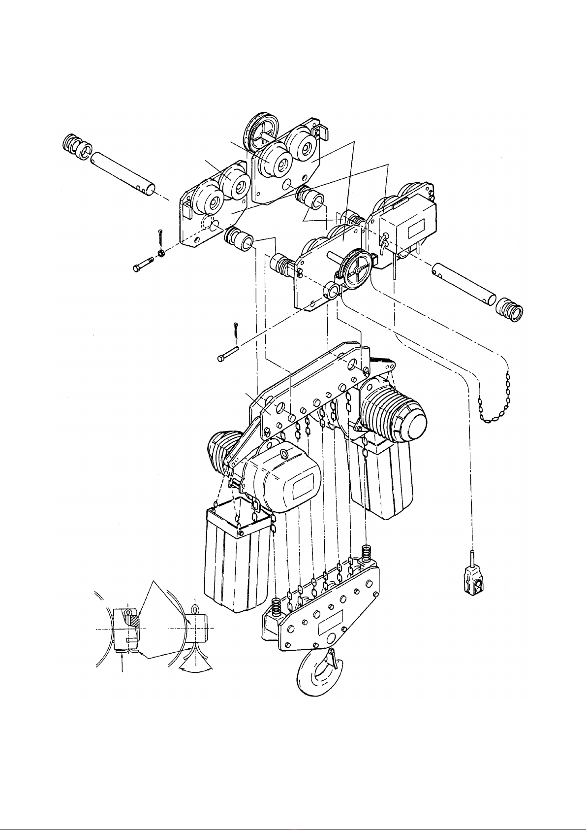
Fig. 8-2 Trolley parts arrangement for ES hoist
Suspension
shaft
Suspension
shaft
Split pin
Split pin
Shaft
stopper pin
(Bolt)
Slotted nut
Adjusting
spacers
Side plate G
Side plate S
Adjusting
spacers
Shaft
stopper pin
Hand chain
Hand wheel
Track wheel G
Track wheel S
Shaft stopper pin
Slotted nut
Suspension
shaft
Split pin
Split pin is
required to be
bent fully.
Requir
ed to be wider
than 70°
ES electric chain hoist
Top suspension plate
—11 —
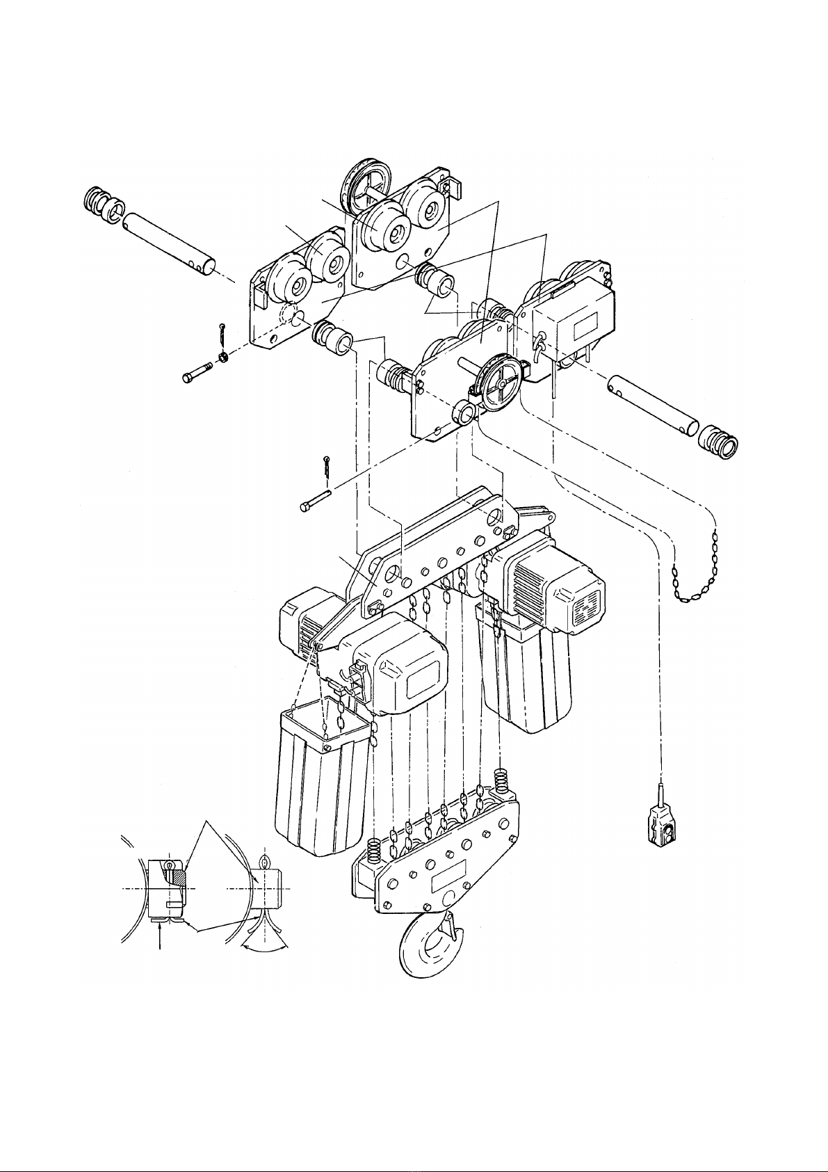
Fig. 8-3 Trolley parts arrangement for ER hoist
Suspension
shaft
Suspension
shaft
Split pin
Split pin
Shaft
stopper pin
(Bolt)
Slotted nut
Adjusting
spacers
Side pate G
Side plate S
Adjustment
spacers
Shaft
stopper pin
Hand chain
Hand wheel
Track wheel G
Track wheel S
Shaft stopper pin
Slotted nut
Suspension
shaft
Split pin
Split pin is
required to be
bent fully.
Required to be wider
than 70
ER electric chain hoist
Top suspension plate
—12 —
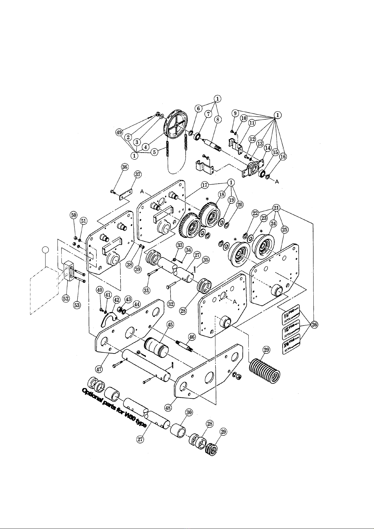
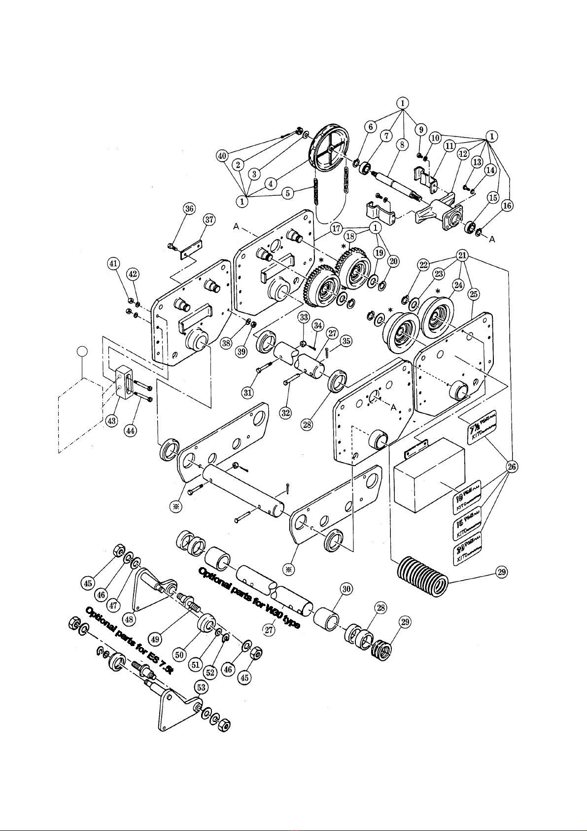
12. PARTS LIST
When ordering replacement parts, please specify WLL, No., part name and quantity.
Fig. 12-1 Parts development - TSG trolley for M3 hoist
* Please chose appropriate wheel type that
matches flange type you use because there
are two options, tapered flange and flat
flange.
—13 —
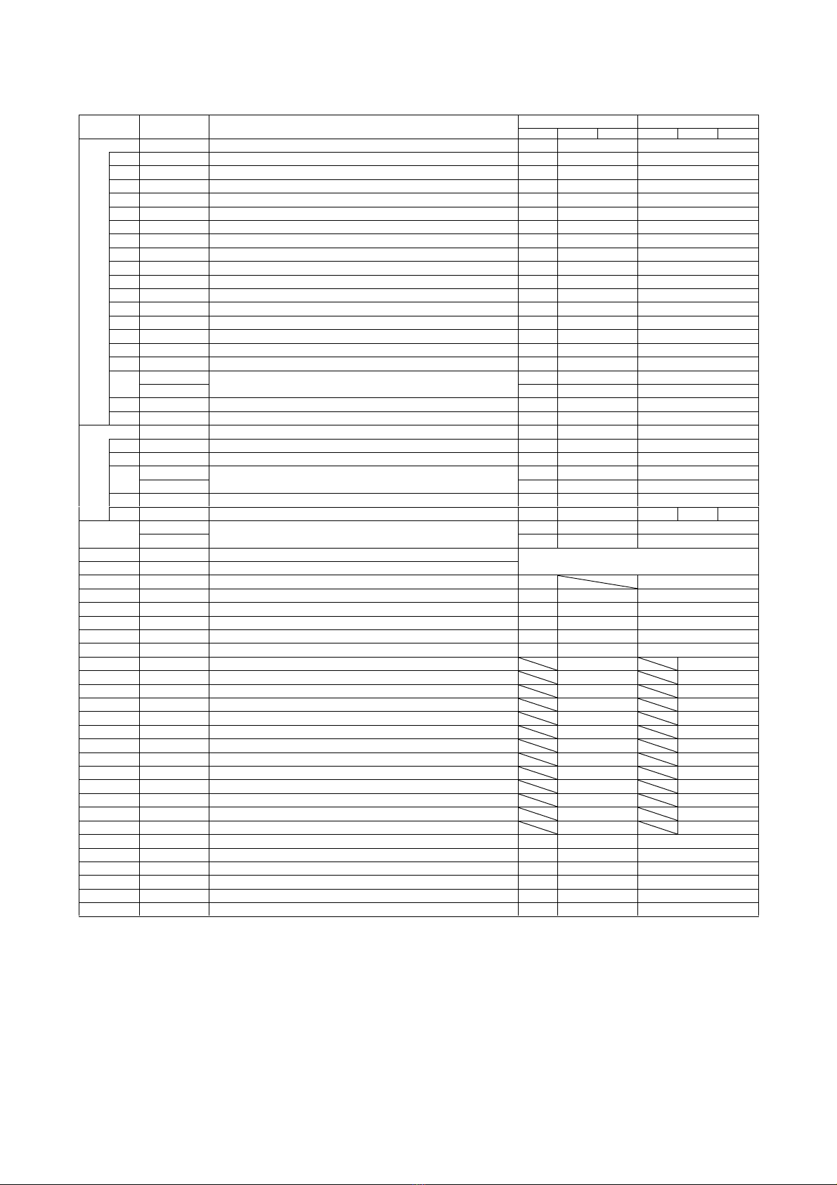
Fig. No. Part No. Part name Nos per Trolley Capacity
7.5t, 10t 15t 20t 7.5t, 10t 15t 20t
1 Side plate G complete set 1 2
2 T3G151 Slotted nut 1 2
3 T3G152 Washer 1 2
4 T3G123 Hand wheel 1 2
5 CF842 Hand chain 1 2
6 T3G132 Snap ring 2 4
7 T3G131 Ball bearing 2 4
8 T3G127 Pinion 1 2
9 T3G163 Socket bolt 4 8
10 E6F854 Spring washer 4 8
11 T3G125 Hand chain guide 2 4
12 M6F575 Socket bolt 4 8
13 M6F576 Spring washer 4 8
14 T3G128 Pinion holder 1 2
15 T3G131 Ball bearing 2 4
16 T3G132 Snap ring 2 4
17 Side plate G assembly 1 2
18 T3G1101 Track wheel G assembly 2B* 4B*
T3G1108 2Z* 4Z*
19 T3G104 Washer 4 8
20 T3G106 Snap ring 4 8
21 Side plate S complete set 1 2
22 T3G106 Snap ring 4 8
23 T3G104 Washer 4 8
24 T3G1102 Track wheel S assembly 2B* 4B*
T3G1109 2Z* 4Z*
25 Side plate S assembly 1 2
26 T3G801 Name plate B 1 1
27 MS115 Suspension shaft 1 2
MS181 1 [W] 2 [W]
28 MS117 Thick spacer See table 5-1 in page 6.
29 MS118 Thick spacer
30 MS182 Fixing spacer 2 [W]
31 MS161 Bolt 1 2
32 MS164 Shaft stopper pin 1 2
33 T3G154 Slotted nut 1 2
34 T3G155 Split pin 1 2
35 T3G157 Split pin 1 2
36 MS106 Bolt 4
37 MS105 Connection plate 2
38 MS174 Spring washer 4
39 MS173 Nut 4
40 T3G168 Bolt 1
41 E6F854 Spring washer 1
42 T3G145 Key plate 1
43 E6S081 Nut 8
44 E6S082 Spring washer 8
45 T3G144 Suspension shaft 1
46 T3G143 Stay bolt 4
47 T3G141 Suspension plate A 1
48 T3G142 Suspension plate B 1
49 T3G160 Split pin 1 2
50 T5G144 Nut 8 8
51 T5G143 Spring washer 8 8
52 T5G141 Bumper 4 4
53 T5G142 Socket bolt 8 8
54 T5AB-1101 Buffer assembly 4 4
Note : [W] indicates wide flange type.
: The parts given no part number in the above table can not be supplied.
* : Symbol Z means track wheel applied to flat flange rail; Symbol B to tapered flange rail.
—14 —
Fig. 12-2 Parts development - TSG trolley for ES or ER hoist
* Please chose appropriate wheel type that
matches flange type you use because there
are two options, tapered flange and flat
flange.

—15 —
Fig No. Part No. Part Name Nos per Trolley Capacity
7.5t, 10t 15t 20t 7.5t 10t 15t 20t
1 Side plate G complete set 1 2
2 T3G151 Slotted nut 1 2
3 T3G152 Washer 1 2
4 T3G123 Hand wheel 1 2
5 CF842 Hand chain 1 2
6 T3G132 Snap ring 2 4
7 T3G131 Ball bearing 2 4
8 T3G121 Pinion 1 2
9 T3G163 Socket bolt 4 8
10 E6F854 Spring washer 4 8
11 T3G125 Hand chain guide 2 4
12 T3G122 Pinion holder 1 2
13 M6F575 Socket bolt 4 8
14 M6F576 Spring waher 4 8
15 T3G131 Ball bearing 2 4
16 T3G132 Snap ring 2 4
17 Side plate G assembly 1 2
18 T3G1101 Track wheel G assembly 2B* 4B*
T3G1108 2Z* 4Z*
19 T3G104 Washer 4 8
20 T3G106 Snap ring 4 8
21 Side plate S complete set 1 2
22 T3G106 Snap ring 4 8
23 T3G104 Washer 4 8
24 T3G1102 Track wheel S assembly 2B* 4B*
T3G1109 2Z* 4Z*
25 Side plate S assembly 1 2
26 T3G801 Name plate B 1 1
27 MS115 Suspension shaft 1 2
MS181 1 [W] 2 [W]
28 MS117 Thick spacer See table 5-1 in page 6.
29 MS118 Thin spacer
30 MS182 Fixing spacer 2 [W] 4 [W]
31 MS161 Bolt 1 2
32 MS164 Shaft stopper pin 1 2
33 T3G154 Slotted nut 1 2
34 T3G155 Split pin 1 2
35 T3G157 Split pin 1 2
36 MS106 Bolt 4
37 MS105 Connection plate 2
38 MS174 Spring washer 4
39 T3G170 Nut 4
40 T3G161 Split pin 1 2
41 T5G144 Nut 8 8
42 T5G143 Spring washer 8 8
43 T5G141 Bumper 4 4
44 T5G142 Socket bolt 8 8
54 T5AB-1101 Buffer assembly 4 4
* Refer to hoist parts list.
45 MS411 Nut 4
46 MS413 Spring washer 4
47 MS412 Washer 2
48 MS5401 Hanger plate A assembly 1
49 MS408 Bolt 2
50 MS1405 Hanger wheel assembly 2
51 MS407 Wheel washer 2
52 MS415 Snap ring 2
53 MS5402 Hanger plate B assembly 1
Note : [W] indicates wide flange type.
: The parts given no part number in the above table can not be supplied.
* : Symbol Z means track wheel applied to flat rail ; symbol B to tapered flange rail.

13. CONTENTS OF EC DECLARATION OF CONFORMITY
We, KITO Corporation,
2000 Tsuijiarai, Showa-cho,
Nakakoma-gun, Yamanashi, 409-3853, Japan
declare under our sole responsibility that the products:
Plain trolley TSP / Geared trolley TSG, model TS2
in capacity range of 500 kg up to 5 tonnes
Geared trolley TSG, model TS1
in capacity range of 7.5 tonnes to 30 tonnes,
to which this declaration relates is in conformity with the following EC directives and standards.
EC directives:
Machinery Directive 2006/42/EC
Harmonized standards:
EN ISO 12100:2010 Risk assessment and risk reduction
EN 818-7:2002+A1:2008 Short link chain for lifting purposes,
increased quality, grade V, certified by
Fachausschuss Metall und Oberflächenbehandlung
EN 13157:2004+A1:2009 Hand powered lifting equipment,
except for the requirement of “5.2.6 Operating effort”
Authorized representative for the arrangement of the technical documents:
Udo Kleinevoß
Technical Manager
Kito Europe GmbH. 40549 Düsseldorf

URL. http://www.kito.co.jp
KITO Europe GmbH
Heerdter Lohweg 93, D-40549 Düsseldorf, Germany
TEL: +49-(0)211-528009-00
FAX: +49-(0)211-528009-59
E-mail: [email protected]
URL: http://www.kito.net/
KITO corporation
Tokyo Head office:
SHINJUKU NS Building 9F, 2-4-1, Nishi-Shinjuku, Shinjuku-ku, Tokyo 163-0809, Japan
URL: http://www.kito.com/
Head office & Factory:
2000 Tsuijiarai Showa-Cho, Nakakoma-Gun, Yamanashi 409-3853, Japan
URL: http://www.kito.com/
Other manuals for TS Series
1
This manual suits for next models
10
Table of contents
Popular Industrial Equipment manuals by other brands


ABB
ABB HT587349 Operation manual

Allen-Bradley
Allen-Bradley 140G-M quick start guide

ubicquia
ubicquia ubigrid DTM+ installation manual

Retsch
Retsch SM300 manual

Clark-Reliance
Clark-Reliance Reliance Simpliport 180 Installation, operation & maintenance instructions

YZ Systems
YZ Systems DynaPak 2010 Series System Support Manual


