Kleenmaid FEG905X Installation guide

FEG905X - 900mm Stainless Steel Freestanding Range
Gas Cooktop, Electric Multi Function Oven

2
PRODUCT LABEL
ongratulations on the purchase of your new
Kleenmaid appliance. This appliance has been
designed and manufactured to give you years
of reliable performance. For best results,
carefully read the instructions on how to install
your new appliance. Correct installation will avoid delays and
unnecessary service calls.
Once installation is complete, read this booklet and get to
know the controls and the features of your new appliance.
We reserve the right to alter the specifications with no
influence on the operation of the appliance. This instruction
manual cannot be reason for a claim.
This cooker has been designed and constructed in accordance with the following
codes and specifications:
AGA101 (AS 4551) Approval Requirements for Domestic Gas cooking appliances
AS/NZS 3350-1 General Requirements for Domestic electrical appliances
AS/NSZ 3350-2-6 Particular Requirements for Domestic electrical cooking appliances
AS/NSZ 1044 Electromagnetic Compatibility Requirements.

3
Important:
This appliance is designed and manufactured solely for the cooking of domestic
(household) food and is not suitable for any non domestic application and there-
fore should not be used in a commercial environment.
The appliance guarantee will be void if the appliance is used within a non domes-
tic environment i.e. a semi commercial, commercial or communal environment.
FIRST TIME USE THE OVEN
It is advised to follow these instructions:
■Clean the interior of the oven with cloth soaked in water and detergent
(neutral) then dry carefully.
■Fit the wire racks as described at chapter “Use and care”.
■Insert shelves and tray.
■Switch on the empty oven on max to eliminate grease tracks from the heating
elements.
IMPORTANT PRECAUTIONS AND RECOMMENDATIONS FOR
USE OF ELECTRICAL APPLIANCES
Use of any electrical appliance implies the necessity to follow a series of fundamental
rules. In particular:
■Never touch the appliance with wet hands or feet;
■do not operate the appliance barefooted;
■The appliance is not intended for use by young children or infirm persons
without supervision
■Young children should be supervised to ensure they do not play with the
appliance
The manufacturer cannot be held responsible for any damages caused by improper,
incorrect or illogical use of the appliance.

4
IMPORTANT PRECAUTIONS AND RECOMMENDATIONS
After having unpacked the appliance, check to ensure that it is not damaged.
In case of doubt, do not use it and consult your supplier or a professionally qualified techni-
cian.
Packing elements (i.e. plastic bags, polystyrene foam, nails, packing straps, etc.) should not
be left around within easy reach of children, as these may cause serious injuries.
■Do not attempt to modify the technical characteristics of the appliance as this
may become dangerous to use.
■Do not carry out cleaning or maintenance operations on the appliance without
having previously disconnected it from the electric power supply.
■After use, ensure that the knobs are in off position.
■Do not allow children or other incapable people to use the appliance without
supervision.
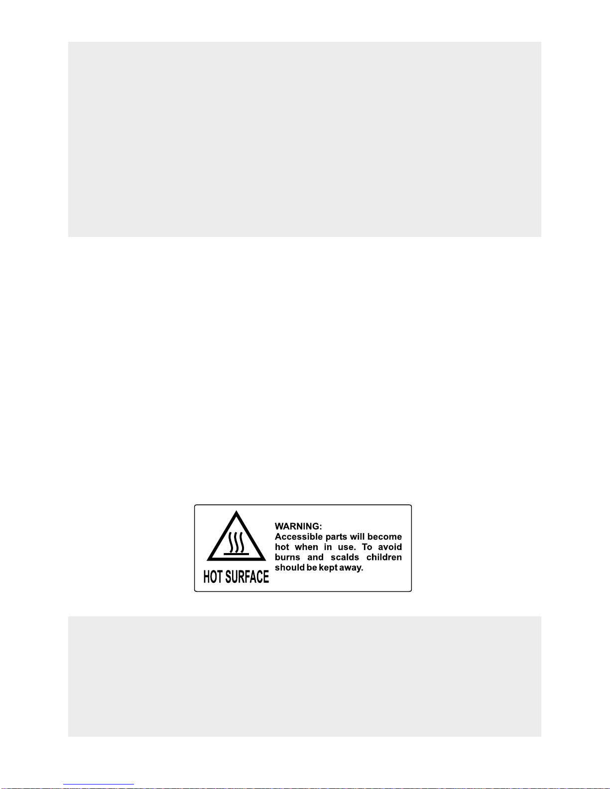
■During and after use of the cooker, certain parts will become very hot. Do not
touch hot parts.
■Keep children away from the cooker when it is in use.
■Some appliances are supplied with a protective film on steel and aluminium parts.
This film must be removed before using the appliance.
■Fire risk! Do not store flammable material in the oven, and in the storage
compartment.
■Make sure that electrical cables connecting other appliances in the proximity of
the cooker cannot come into contact with the hob or become entrapped in the
oven door.
■Do not line the oven walls with aluminium foil. Do not place baking trays or the
drip tray on the base of the oven chamber.
■The manufacturer declines all liability for injury to persons or damage to property
caused by incorrect or improper use of the appliance.
■To avoid any possible hazard, the appliance must be installed by qualified
personnel only. Any repairs by unqualified persons may result in electric shock or
short circuit. In order to avoid possible injuries to your body or to the appliance,
do not attempt any repairs by yourself. Such work should be carried out by
qualified service personnel only.
■Danger of burns! The oven and cooking accessories may become very hot
during operation. Make sure children are kept out of reach and warn them
accordingly. To avoid burns use kitchen clothes and gloves when handling hot
parts or utensils.
■Never clean the oven with a high-pressure steam cleaning device, as it may
provoke a short circuit.
■This appliance is intended for use in your household. Never use the appliance for
any other purpose!
■IMPORTANT NOTE: This appliance shall not be used as a space
heater, especially if installed in marine craft or caravans.

5
INSTALLATION
CAUTION:
■
This appliance must be installed in accordance with these installation
instructions.
■
This appliance shall only be serviced by authorized personnel.
■
This appliance is to be installed only by an authorised person.
■
Incorrect installation, for which the manufacturer accepts no responsibility,
may cause personal injury of damage.
■
Always disconnect the cooker from mains power supply before carrying out
any maintenance operations or repairs.
■
In the room where the cooker is installed, there must be enough air to
allow the gas to burn correctly, according to the current local regulations.
ELECTRICAL REQUIREMENTS
■The appliance must be connected to the mains checking that the voltage corre-
sponds to the value given in the rating plate and that the electrical cable sec-
tions can withstand the load specified on the plate.
■The plug must be connected to an earthed socket in compliance with safety
standards.
■If the appliance is supplied without plug, fit a standard plug which is suitable for
the power consumed by the appliance.
■The appliance must be connected directly to the mains placing a two pole
switch with minimum opening between the contacts of 3 mm between the
appliance and the mains.
■The power supply cable must not touch the hot parts and must be positioned so
that it does not exceed 50°C above ambient.
■Once the appliance has been installed, the switch or socket must always be
accessible.
■
If the supply cord is damaged it must be replaced by the manufacturer or
it’s Service Agent or a similarly qualified person in order to avoid a hazard.
WARNING: This cooker must be connected to electrical supply using
V105 insulated cable.
N.B. The connection of the appliance to earth is mandatory.
If the installation requires alterations to the domestic electrical system call a qualified
electrician.
He should also check that the socket cable section is suitable for the power drawn by
the appliance.
Replacing the power cord must be done by a qualified electrician in accor-
dance with the instructions supplied by the manufacturer and in compliance
with established electrical regulations.

6
CLEARANCES
Installation clearances and protection of combustible surfaces shall comply with
the current local regulations eg. AG 601 (AS 5601) Gas Installations code.
Installation shall comply with the dimension in Fig 1 bearing in mind that
Overhead Clearances
In no case shall the clearances between the highest part of the cooker be less than
650mm for an overhead exhaust fan. The recommended distance for canopy or island
exhaust fans is 750mm. Please check these measurements with your local gas, electri-
cal and building authority. AII other downward facing combustible surfaces less than
600mm above the cooker surface shall be protected for the full width of the cooking
surface in accordance with the standards noted above. In no case shall the clearance
be less than 450mm.
Rear and Side Clearances
Where the dimensions from the periphery of the nearest burner to any vertical com-
bustible surface is less than 200mm the surface shall be protected in accordance with
the standards to a height of not less than 150mm above the cooking surface for the
full width or depth of the cooking surface
Where the dimensions from the periphery of the nearest burner to any horizontal com-
bustible surface is less than 200 mm, the horizontal surface shall be greater than 10
mm below the surface of the hob, or the horizontal surface requirement above.
Protection of combustible surfaces.
The standards above specify that where required protection shall ensure that the sur-
face temperature of the combustible surface does not exceed 65°C above room tem-
perature.
If the cooker is located on a pedestal it is necessary to provide safety
measures to prevent falling out.
750 mm
A
U
T
O
450 mm
50 mm
500 mm
Cooker overall dimensions [mm]
• height: min 900 - max 925
• width: 900
• depth: 600
Figure 1

7
LEVELLING THE COOKER
The cooker may be levelled by screwing the lower ends of the feet IN or OUT (fig. 4).
Figure 4
Figure 2
FITTING THE ADJUSTABLE FEET
The adjustable feet must be fitted to the base of the cooker before use.
Rest the rear of the cooker an a piece of the polystyrene packaging exposing the
base for the fitting of the feet.
Fit the 4 legs by screwing them tight into the support base as shown in figure 3.
Figure 3

8
WARNING
When moving cooker to its final posi-
tion DO NOT DRAG (fig. 7).
Lift feet clear of floor (fig. 5).
Figure 6 Figure 7
Figure 5
WARNING
When raising cooker to upright position always ensure two people carry out
this manoeuvre to prevent damage to the adjustable feet (fig. 5).
MOVING THE COOKER
WARNING
Be careful: do not lift the cooker
by the door handle when raising
to the upright position (fig. 6).

9
Figure 8
ANTI-TILT BRACKET
Fixing the anti-tilt bracket:
■After you have located where the cooker is to be positioned mark, on the wall,
the place where the 2 screws of the anti-tilt bracket have to be fitted. Please fol-
low the indications given in the drawing below.
■Make two holes of diameter 8mm diameter on the wall and insert the plastic
plugs.
■Attach the anti-tilt bracket loosely by means of 2 screws.
■Move the cooker to the wall and adjust the height of the anti-tilt bracket so that
it can engage in one slot of the cooker back.
■Attach the anti-tilt bracket tight.
■Push the cooker against the wall so that the anti-tilt bracket is fully inserted in
one slot of the cooker back.
min 220
max 245
450 450
900 mm
0
+ 25

10
GAS SUPPLY:
■The connection must be executed by an authorised person according to the rele-
vant standards.
■Before connecting the appliance to the gas main, mount the brass conical adaptor
onto the gas inlet pipe, upon which the gasket has been placed (figures 9-10).
Conical adaptor and gasket are supplied with the appliance (packed with conver-
sion kit for use with Natural gas or Propane gas).
■This appliance is suitable for use with Natural Gas or Propane gas. (Check the “gas
type” sticker attached to the appliance).
■For Natural Gas models the gas supply is connected to the pressure regulator
which is supplied with the appliance (fig. 10). Adjust the regulator to obtain a test
point pressure of 1 kPa with the two semi-rapid (SR) burners operating at the maxi-
mum.
■For Propane gas models the gas supply is connected to the test point adaptor
which is supplied with the appliance (fig. 9) and ensure that the supply pressure is
regulated to 2.75 kPa.
■The connection must be made at the rear of appliance (left or right); the pipe do
not cross the cooker.
■The inlet not used must be closed off with the cap and sealing gasket supplied.
■IMPORTANT: Use two spanners to tighten or loosen the connecting pipe (fig. 12)
Gas connection for
PROPANE GAS
Figure 10
Figure 9
Gas connection for
NATURAL GAS
Gas inlet pipe
Nipple
Gasket
Brass conical adaptor
(Thread tight: use
suitable seal)
Gas inlet pipe
Nipple
Gasket
Brass conical adaptor
(Thread tight: use
suitable seal)
Gas regulator
Test point adaptor
Test
point
Test
point

11
1. After connecting the gas supply, check the piping and connections for leaks using
a soap and water solution. The presence of bubbles indicates a leak, tighten or
replace connections as appropriate.
Warning: Do not use any naked flame to check for leaks.
2. Adjust the test point pressure or supply pressure to the value which is appropriate
for the gas type.
3. The operation of the appliance must be tested when installation is completed.
4. Turn on the appliance gas controls and light each burner individually and in com-
bination. Check for a well defined blue flame without any yellow tipping. If any
abnormality is evident then check that the burner cap is located properly and the
injector nipple is aligned correctly.
5. Check the minimum burner setting by quickly rotating the gas control knob from
the maximum to the minimum position, the flame must not go out. If adjustment is
required carry out the “minimum burner setting adjustment" procedure described
6. If satisfactory performance cannot be obtained, the installer shall check the installa-
tion and notify the local gas supply authority for a gas supply problem, or if it is an
appliance problem, our Customer Service Centre should be called to obtain the
nearest authorized Service Agent.
WARNING, This appliance IS NOT SUITABLE for installation with a hose
assembly.
Plug
Figure 11 Figure 12

12
CONVERSION PROCEDURE (to convert to Propane gas)
REPLACING THE INJECTORS
This appliance is suitable for use with Natural gas or Propane gas (check the “gas type”
sticker attached to the appliance). A label stating the type of gas used after replacing
the injectors must be attached at the rear of the appliance, in proximity of the gas
inlet connection. The nominal gas consumption and injector size details are provided
in table at page 14.
To replace the injectors proceed as follows:
■Remove pan supports and burners from the cooktop.
■Using a spanner, remove the injector J (fig. 13, 14) and replace it with one
according to the gas type (see following tables - page 14).
■Affix to the rear of the appliance, in proximity of the gas inlet connections, the
warning label (supplied with the conversion kit) stating that the cooker has
been converted for use with Propane gas / Natural gas.
IMPORTANT
■If the cooker is suitable for use with Natural gas and must be converted for use
with Propane gas, before connecting to gas main remove the appliance gas
regulator and replace with test point adaptor (see fig. 9-10)
■If the cooker is suitable for use with Propane gas and must be converted for use
with Natural gas, before connecting to the gas main remove the appliance test
point adaptor and replace with gas regulator (see figs. 9-10).
NOTE:
Gas regulator and test point adaptor are supplied with the appliance (packed with
conversion kit)
The burners are designed so that regulation of primary air is not required.
Figure 13
J
Figure 14
J

13
MINIMUM BURNER SETTING ADJUSTMENT
Check whether the flame spreads to all burner ports when the burner is lit with the gas
tap set to the minimum position. If some ports do not light, increase the minimum gas
rate setting.
Check whether the burner remains lit even when the gas tap is turned quickly from
the maximum to the minimum position. If the burner does not remain lit, increase the
minimum gas rate setting.
The procedure for adjusting the minimum gas rate setting is described below.
■Turn on the burner
■Turn the tap to the MINIMUM position
■Take off the knob
■With a small flat screwdriver turn the screw “F” (fig. 15) to the correct regulation.
Normally for Propane gas, the regulation screw is tightened up.
Figure 15
F

14
LUBRICATION OF THE GAS TAPS
If the gas tap becomes stiff, it is necessary to dismantle it carefully and clean it with petroleum
spirit. Specialist high temperature resistant grease should be used to lubricate the tap before
replacing.
The operations must be carried out by an authorised person/service agent.
TABLE FOR THE CHOICE OF THE INJECTORS
Natural gas Propane gas
Test Point Pressure [kPa] 1.0 2.75
BURNER
Auxiliary (A) 0.85 3.60 0.53 3.60
Semi-rapid (SR) 1.12 6.30 0.70 6.30
Rapid (R) 1.45 10.30 0.91 10.80
Triple ring (TC) 1.65
13.00
0.95 11.90
Gas
Consumption
[MJ/h]
Injector
Orifice Dia.
[mm]
Gas
Consumption
[MJ/h]
Injector
Orifice Dia.
[mm]
Figure 16

15
USE and CARE
CAUTION:
■This appliance must be used only for the task it has explicitly been designed for,
that is for domestic cooking of foodstuffs. Any other form of usage is to be con-
sidered as inappropriate and therefore dangerous.
■Do NOT place combustible materials or products on this appliance at any time.
■Do NOT spray aerosols in the vicinity of this appliance while it is in use.
USING THE OVEN FOR THE FIRST TIME
■Clean the inside of the oven with a cloth soaked in water and neutral detergent
and dry thoroughly.
■Slide in the catalytic liners and wire racks on the oven wall as in Fig. 17.
■Slide in the grease filter on the back of the oven as in Fig. 18.
■Position the shelf and tray as per Fig. 19.
■To eliminate traces of grease in manufacture it is necessary to pre-heat the oven
at the maximum temperature.
•For 60 minutes in the position, for 30 minutes in the position and for
another 15 minutes in the position.
Figure 17

16
Figure 19
Figure 18
GREASE FILTER
■A special screen is provided at the back of the oven to catch grease particles,
mainly when meat is being roasted (fig. 18).
■When backing pastry etc. this filter should be removed.
■Always clean the filter after cooking as any solid residues on it might adversely
affect the oven performance.

17
24
15
3
6
Figure 20
GAS HOB
GAS BURNERS Natural Gas Propane gas
MJ/h MJ/h
1. Triple ring burner (TC) 13.0 11.9
2. Semi-rapid burner (SR) 6.3 6.3
3. Rapid burner (R) 10.3 10.8
4. Semi-rapid burner (SR) 6.3 6.3
5. Auxiliary burner (A) 3.6 3.6
6. Auxiliary burner (A) 3.6 3.6

18
Figure 21
LIGHTING GAS BURNERS
FITTED WITH SAFETY VALVE DEVICE AND ELECTRONIC IGNITION
■Check that the electricity is
switched on to allow spark igni-
tion.
■Make sure that all controls are
turned to zero.
■The gas flow to the burners is
controlled by taps with a safety
cutout device. If the burner
flame should go out, the safety
cut-off valve will automatically
stop the gas flow. The switch for
the electric ignition is incorporat-
ed in the knobs.
■You control the flow by turning the knob indicator to line up with the following
symbols:
– Symbol ●: tap closed
(burner off)
– Symbol : High (maximum)
– Symbol : Low (minimum)
■To ignite automatically, push the required knob down and turn it to maximum,
keeping the knob down until the burner lights. When the flame is lit, wait for
about ten second with the knob down (safety cut-off activation delay).
■You can control the temperature by the knob to “High” from “minimum”.
■To switch off, turn the knob clockwise until you hear the safety click.
■Note that, if you are using a burner at the minimum setting, you turn the knob
clockwise past the maximum setting before reaching the off position.
■Whenever the lighting of the burners is difficult due to peculiar conditions of
the gas features or supply, it is advised to repeat the ignition with the knob on
“minimum” position.
■If when lighting any of the burners an abnormal flame appears, switch the
burner off and relight using the minimum setting.
■If the flame is still not correct, turn the burner off and call our Customer Service
center for your nearest Authorized Service Agent.
■In the case of a mains failure light the burner with a match or lighted taper.

19
CHOICE OF BURNER
Burners Pan diameter
Auxiliary *12 - 14 cm
Semi-rapid 16 - 24 cm
Rapid 24 - 24 cm
Triple ring 26 - 28 cm
Wok max 36 cm
(*): minimum diameter 6 cm when using
the grid for small pans (fig. 25).
The burner must be chosen according to the diameter of the pans and energy
required.
For optimum efficiency use a wok or pan no smaller than 230 mm diameter.
Saucepans with handles which are excessively heavy, in relationship to the weight
of the pan, are safer as they are less likely to tip.
Pans which are positioned centrally on burners are more stable than those which
are offset.
It is far safer to position the pan handles in such a way that they cannot be
accidentally knocked.
When deep fat frying fill the pan only one third full of oil.
DO NOT cover the pan with a lid and DO NOT leave the pan unattended.
In the unfortunate event of a fire, leave the pan where it is and turn off all
controls.
Place a damp cloth or correct fitting lid over the pan to smother the flames.
DO NOT use water on the fire.
Leave the pan to cool for at least 30 minutes.
Figure 22
do not use pans with concave or
convex bases
AIR FLOW
(cooling fan) AIR FLOW
(cooling fan)
CORRECT USE OF RAPID BURNER
Figure 23

20
Figure 24a Figure 24b
Figure 25
CORRECT USE OF TRIPLE-RING BURNER
■The flat-bottomed pans are to be placed directly onto the pan-support.
■To use the WOK, you must place the wok stand in the CORRECT position as
shown in Fig. 24a-24b.
WRONG CORRECT
GRATE FOR SMALL PANS
This grate is to be placed on top of the
(smaller) auxiliary burner when using
small diameter pans, in order to prevent
them from tipping over.
Table of contents
Other Kleenmaid Range manuals