Kleinn Air Horns RAMHD-734KIT User manual

RAMHD-734KIT
Installation and Operation Manual
Go to Table of Contents PG 2/40 REV: A (6/11/2021)
Table of Contents
1. How to Use this Manual .....................................................................................................................................4
2. Safety First..........................................................................................................................................................4
3. Application Chart................................................................................................................................................5
4. Kit Installation Overview ....................................................................................................................................6
4.1. Approximate Installation Time...................................................................................................................7
5. List of Tools and Supplies ...................................................................................................................................8
5.1. Standard Tool List (Required).....................................................................................................................8
5.2. Special Tool List (Recommended) ..............................................................................................................8
5.3. Shop Consumables List (Recommended)...................................................................................................8
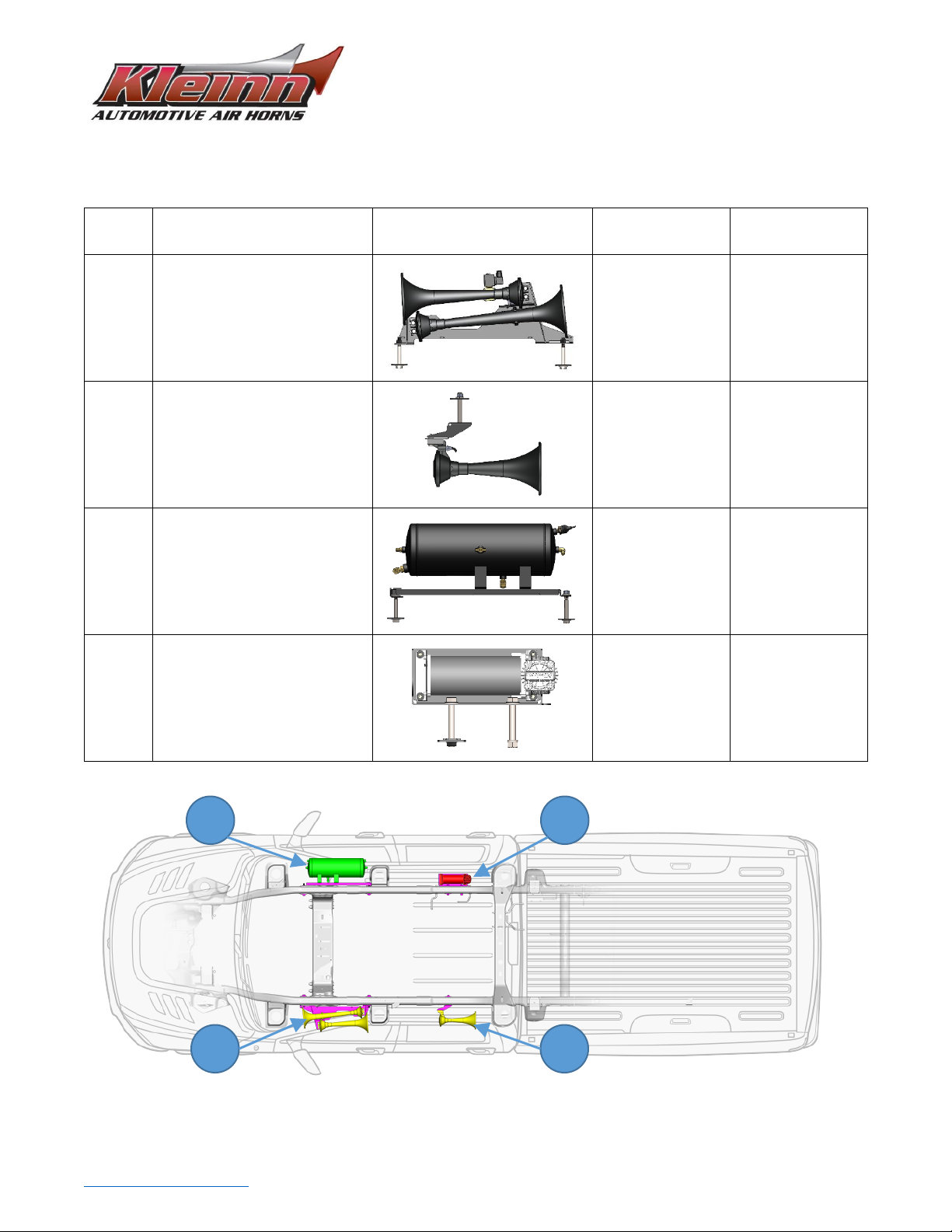
6. Parts List .............................................................................................................................................................9
7. Bench Assembly Steps..................................................................................................................................... 13
7.1 Unpack and Layout Kit Parts.................................................................................................................... 13
7.2 Disassemble Train Horn Kit...................................................................................................................... 13
7.3 Mount Medium and Large Horn Drivers to Bracket................................................................................ 15
7.4 Mount Small Horn Driver to Bracket....................................................................................................... 17
7.5 Mount Air Tank to Bracket ...................................................................................................................... 18
8. On-Vehicle Mechanical Assembly Steps.......................................................................................................... 20
8.1 Large-Medium Horn Assembly Installation............................................................................................. 20
8.2 Small Horn Assembly Installation............................................................................................................ 23
8.3 Air Tank Assembly Installation ................................................................................................................ 26
8.4 Compressor and Bracket Installation ...................................................................................................... 29
9. On Vehicle Air Line Installation ....................................................................................................................... 32
10. On Vehicle Electrical Installation................................................................................................................. 35
10.1. Disconnect Vehicle Battery(s).............................................................................................................. 35
10.2. Attach Relay to Vehicle........................................................................................................................ 35
10.3. Route Wiring and Install Horn Button................................................................................................. 35
10.4. Connect Relay to Wiring...................................................................................................................... 36
10.5. Connect Air Horn Solenoid .................................................................................................................. 36
10.6. Reconnect Vehicle Battery(s) .............................................................................................................. 36
11. Initial Testing of Kit...................................................................................................................................... 37
11.1. Test Air Compressor ............................................................................................................................ 37
11.2. Test Train Horns................................................................................................................................... 37

RAMHD-734KIT
Installation and Operation Manual
Go to Table of Contents PG 3/40 REV: A (6/11/2021)
11.3. Test Quick Connect Coupler ................................................................................................................ 37
12. General Operation of Kit ............................................................................................................................. 38
12.1. Compressor Operation ........................................................................................................................ 38
12.2. Horn Operation.................................................................................................................................... 38
13. Routine Maintenance.................................................................................................................................. 39
14. Warranty Information ................................................................................................................................. 40

RAMHD-734KIT
Installation and Operation Manual
Go to Table of Contents PG 4/40 REV: A (6/11/2021)
1. How to Use this Manual
Open this digital PDF manual using Adobe Reader ®, or equivalent to take advantage of following key features:
•Hyperlinks (blue underlined text) allow access to additional content via internet; click/tap to activate
•Table of Contents page allows easily navigating this manual; click/tap any section line to go to it
•Bookmarks (open Adobe Reader ® Navigation Pane) allow quickly navigating to any section; click/tap
•Zoom IN on pictures by pressing “CTRL and +” at same time on PC, or pinch in on smart devices
•Zoom OUT on pictures by pressing “CTRL and -”at same time on PC, or pinch out on smart devices
To install Adobe Reader ®
On PC, or Mac
•visit https://get.adobe.com/reader/otherversions/
On Android, iPhone/iPad, and Windows devices,
•visit https://acrobat.adobe.com/us/en/acrobat/mobile-app.html
2. Safety First
Read manual thoroughly before starting installation of this kit. Verify you have all parts listed and that you
clearly understand this installation procedure. Contact Kleinn technical support for any questions.
Installation of this kit requires moderate mechanical aptitude; seek professional help if you’re not competent
using hand tools in tight uncomfortable spaces, and around possibly rusted and sharp vehicle parts.
Before starting, obtain proper tools required to perform installation correctly, adequate lighting, eye protection,
hearing protection for operating train horns, and hand protection to guard against sharp edges and metal burrs,
which may be present on kit parts and vehicle parts.
Throughout this manual the following words may be used; be aware of their meaning and application.
CAUTION: means damage could occur to vehicle, or kit parts during, or after installation
WARNING: means injury could occur to you or others, including damage to vehicle, or kit parts
DANGER: means serious injury or death could occur to you or others during installation

RAMHD-734KIT
Installation and Operation Manual
Go to Table of Contents PG 5/40 REV: A (6/11/2021)
3. Application Chart
RAMHD-734KIT is a 100%** direct bolt-on aftermarket product for all DODGE vehicles listed in below chart
MODEL YR
MODEL
DRIVE
ENGINE
BODY
TRIM
2014-2021
RAM 2500
2WD, 4WD
ALL
Crew Cab (short
bed**), Mega Cab
ALL
2014-2021
RAM 3500
2WD, 4WD,
DUALIE
ALL
Crew Cab (short
bed**), Mega Cab
ALL
**Exclusions:
All vehicles listed may require drilling holes for ground wires and installing switches, based on preference of
installed switch locations and wire grounding points.
Crew Cab Long Bed, or Regular/Standard Cab frames; these frames will require drilling holes to attach following
brackets. Contact Kleinn sales for more information.
1. Small Horn Bracket –drill mounting holes for hardware in approximate location shown in instructions
2. Compressor Bracket –drill mounting holes for hardware in approximate location shown in instructions
Product Compatibility:
This kit has been designed and tested to be compatible with leading manufacturers of aftermarket truck steps,
such as Amp Research Power Steps ® and all OEM standard and optional steps.

RAMHD-734KIT
Installation and Operation Manual
Go to Table of Contents PG 6/40 REV: A (6/11/2021)
4. Kit Installation Overview
RAMHD-734KIT consists of the following major components, located on vehicle per following pictures and chart
ITEM
DESCRIPTION
PICTURE
MOUNTING
LOCATION
APPROX.
INSTALL TIME
1
730 Series Large and
Medium Horn with
Mounting Bracket and Air
Solenoid
Under driver side
front door.
Bolted to outside
of frame rail.
2+ Hours
2
730 Series Small Horn with
Mounting Bracket
Under driver side
rear door.
Bolted to outside
of frame rail.
1-2 Hours
3
Air Tank with Mounting
Bracket
Under passenger
side front door.
Bolted to outside
of frame rail.
2+ Hours
4
Air Compressor with
Mounting Bracket
Under passenger
side rear door.
Bolted to outside
of frame rail.
1-2 Hours
Top View –Ram 2500 Crew Cab Short Bed
4
3
1
2

RAMHD-734KIT
Installation and Operation Manual
Go to Table of Contents PG 7/40 REV: A (6/11/2021)
Driver Side View –2014 Ram 2500 Crew Cab Short Bed
Passenger Side View –2014 Ram 2500 Crew Cab Short Bed
4.1. Approximate Installation Time
RAMHD-734KIT is a multi-faceted product consisting of multiple mechanical, electrical, and pneumatic
components.
For a typical home mechanic, or auto enthusiast, a professional installation job with setup and testing of
final product, is estimated to take:
•8-12 Hours
1
2
3
4

RAMHD-734KIT
Installation and Operation Manual
Go to Table of Contents PG 8/40 REV: A (6/11/2021)
5. List of Tools and Supplies
5.1. Standard Tool List (Required)
1. Basic mechanic’s 3/8” drive socket sets with extensions
a. Inch Size Sockets (1/4” – 1” Hex)
b. Metric Size Sockets (6mm –20mm Hex)
2. Basic mechanic’s combination wrenches (box/open-end)
a. Inch Size Wrenches (1/4” – 1” Hex)
b. Metric Size Wrenches (6mm –20mm Hex)
3. Basic mechanic’s screwdriver set (Philips, Flat Head)
4. Diagonal Cutter/Wire Cutter Pliers
5. Wire Strippers
6. Wire Terminal Crimpers
7. Slip-Joint Pliers
8. Utility Knife, or Utility Razor blade
5.2. Special Tool List (Recommended)
1. 10-100 ft.-lb. torque wrench
2. 50-150 in.-lb. torque wrench
a. For English to Metric torque conversions, reference Norbar online calculator, or similar.
3. Multi-Meter for 12V DC electrical systems, or equivalent
4. 12V DC Test Light, or equivalent
5.3. Shop Consumables List (Recommended)
1. Quality Electrical tape
2. Di-electric grease for electrical connections
3. Heat Shrink tubing for electrical connections
4. Sand Paper, or Wire Brushes for installing ground wires
5. Extra plastic zip ties > 6” long
6. Extra NPT sealant (i.e., Kleinn Air Horn Juice, Teflon tape, etc.)
7. Touch-up paint for frame/chassis
8. Typical cleanup supplies

RAMHD-734KIT
Installation and Operation Manual
Go to Table of Contents PG 9/40 REV: A (6/11/2021)
6. Parts List
RAMHD-734KIT includes following items
ITEM
QTY
PART NUMBER
DESCRIPTION
PICTURE
1
1
6450RC
6450RC Compressor Kit,
with included hardware,
and remote air supply
line
2
1
730
730 Series Horn Kit, with
included solenoid/valve,
and 1/4” Air Tubing, 12
ft. long
3
1
6355RT
Air Tank
4
2
25014
1/4” Air Tubing, 12 ft.
long
5
2
51414L
(view location on Air Tank)
1/4” NPT X 1/4”
Compression Fitting, 90
Deg Elbow
6
1
52835
(view location on Air Tank)
1/4” NPT, Drain Valve
7
1
52175
(view location on Air Tank)
1/4” NPT, 175 PSI Safety
Valve

RAMHD-734KIT
Installation and Operation Manual
Go to Table of Contents PG 10/40 REV: A (6/11/2021)
8
1
51414F
1/4” NPT FEMALE X 1/4”
Compression Fitting
9
1
51214L
(view location on Air Tank)
1/4” NPT X 1/2”
Compression Fitting, 90
Deg Elbow
10
1
51214R
(view location on Air Tank)
1/2” NPT FEMALE X 1/4”
NPT Reducer Fitting
11
1
2151
(view location on Air Tank)
1/4” NPT Pressure
Switch
12
1
1302
Quick Connect Air
Coupler Kit, with
relocation bracket
13
1
320
Remote Horn Button
14
1
WIRE KIT
Full Wire Kit, with
electrical connectors
and zip ties

RAMHD-734KIT
Installation and Operation Manual
Go to Table of Contents PG 11/40 REV: A (6/11/2021)
15
1
RAMHD HARDWARE
1/2”-13 Bolts, Nuts, and
Washers for bracket
mounting
16
1
4 BOLT TANK HARDWARE
7/16”-14 Bolts, Nuts,
and Washers for tank
mounting
17
1
HORN SEPARATION
HARDWARE
5/16”-18 Bolts, Nuts,
and Washers for horn
mounting
18
1
¼” WIRE LOOM, 20 ft. Long
1/4” Wire loom for
electrical routing
19
1
1/8” WIRE LOOM, 10 ft. Long
1/8” wire loom for
electrical routing
20
1
INF-1
Inflator Kit, with Air
Hose and Bag
21
1
RAMHD_HORN-LG_BRKT-ASSY
Medium-Large Horn
Bracket

RAMHD-734KIT
Installation and Operation Manual
Go to Table of Contents PG 12/40 REV: A (6/11/2021)
22
1
RAMHD_HORN-SM_BRKT
Small Horn Bracket
23
1
RAMHD_TANK_BRKT-ASSY
Air Tank Bracket
24
1
RAMHD-200
Air Compressor Bracket
25
6
RAMHD_WASHER
Washer for Frame Slots
26
1
KLEINN AIR HORN JUICE
Thread Sealant for NPT
Fittings
27
1
RAMHD-201
(for 2019+ RAMHD)
Compressor Bracket Bolt
Tie

RAMHD-734KIT
Installation and Operation Manual
Go to Table of Contents PG 13/40 REV: A (6/11/2021)
7. Bench Assembly Steps
Complete following steps off vehicle to facilitate final installation.
7.1 Unpack and Layout Kit Parts
Unpackage RAMHD-734KIT and verify all parts are included per above Parts List. Contact Kleinn support if any
questions arise.
It is recommended to layout and organize parts across a large work bench, or table in following order:
1. Review train horn box and included hardware
2. Review air compressor box and included hardware
3. Review air tank box and included hardware
4. Review kit mounting brackets and included hardware
5. Review electrical/air fittings and included wiring and tubing
7.2 Disassemble Train Horn Kit
1. Remove trumpets from drivers and set aside.
a. Starting with largest trumpet, tightly grasp trumpet with both hands and unscrew counter
clockwise; trumpet may be very tight. Repeat on medium trumpet, then small.
i. Drivers are identical and do not require marking Small, Medium, Large
b. If necessary, clamp horn mounting plate to rigid table, in vise, or seek help to hold plate.
2. Cut semi-rigid plastic air tubing between horns.
a. Use sharp side/diagonal cutters, or equivalent to safely sever tubing.

RAMHD-734KIT
Installation and Operation Manual
Go to Table of Contents PG 14/40 REV: A (6/11/2021)
WARNING: tubing is difficult to sever using any type of fixed blade (i.e., knife, razor blade, box
cutter, etc.)
3. Loosen Compression Nuts on center driver and remove horn drivers from mounting plate.
a. Use properly sized socket, or box-end wrench.
b. Horn mounting plate and fasteners will NOT be re-used during installation.
4. Remove cut tubing from fittings.
a. Using slip-joint pliers, or equivalent, pull and twist off tubing connected to compression fittings.
b. Depress collar on quick release fitting with one hand, then twist and pull plastic tube out with
other hand. If necessary, use slip-joint pliers, or equivalent to twist and pull tubing out.
c. For further instruction on properly using quick fittings, reference this SMC Video
d. Discard old tubing.

RAMHD-734KIT
Installation and Operation Manual
Go to Table of Contents PG 15/40 REV: A (6/11/2021)
7.3 Mount Medium and Large Horn Drivers to Bracket
1. Attach Horn Driver to bracket with Large trumpet and Ore Mount, per below illustration.
a. Use Horn Separation Hardware kit
i. Assemble fasteners clean and dry using proper socket and box-end wrench.
b. Do not use Ore Mount Rubber Bushing (included in kit).
2. Attach Air Solenoid and fitting to Horn Driver with built-in tee and attach to bracket, per below
illustration.
a. Apply two small drops of Kleinn Air Horn Juice to male pipe threads.
i. Hand-tighten each fitting, then further tighten with wrench 1/4-1/2 turn
ii. Verify that air flow arrow on Solenoid points to horn driver and facing up.
b. Use Horn Separation Hardware kit and hand-tighten fasteners to bracket.
i. Assemble fasteners clean and dry using proper socket and box-end wrench
ii. Final tightening will be completed on vehicle.

RAMHD-734KIT
Installation and Operation Manual
Go to Table of Contents PG 17/40 REV: A (6/11/2021)
7.4 Mount Small Horn Driver to Bracket
1. Attach Small Horn Driver to bracket, per below illustration
a. Use Horn Separation Hardware kit
i. Assemble fasteners clean and dry, and finger tighten; they should be tight enough that
horn driver does not move freely, but can be repositioned with some hand force.
ii. Final tightening will be completed on vehicle.
iii. Observe correct driver orientation, based on specific vehicle.
Crew Cab Orientation (top slots - bracket facing to right)
Mega Cab Orientation (bottom slots - bracket facing to right)

RAMHD-734KIT
Installation and Operation Manual
Go to Table of Contents PG 18/40 REV: A (6/11/2021)
7.5 Mount Air Tank to Bracket
1. Attach and tighten air fittings to tank, per below illustrations.
a. Apply two small drops of Kleinn Air Horn Juice to each male pipe thread.
b. Hand-tighten each fitting, then further tighten each 1/4-1/2 turn using proper sized box-end
wrench; adjust as necessary to match fitting orientation shown.
c. Match item numbers to Parts List
5
6
11
5
10
9
7

RAMHD-734KIT
Installation and Operation Manual
Go to Table of Contents PG 19/40 REV: A (6/11/2021)
2. Attach air tank to bracket, per below illustration.
a. Use 4 Bolt Tank Hardware kit
i. Assemble fasteners clean and dry; tank should not move freely, but can be repositioned
with some hand force.
ii. Final tightening will be completed on vehicle.
This manual suits for next models
1
Table of contents
Other Kleinn Air Horns Horn manuals
Popular Horn manuals by other brands

Vixen Horns
Vixen Horns VXH4318 installation guide

Vixen Horns
Vixen Horns VXO8815/3118B installation guide

Vixen Horns
Vixen Horns VXO8560/4124C installation guide

Vixen Horns
Vixen Horns VXH4114B installation guide

Vixen Horns
Vixen Horns La Cucaracha VXH6803B installation guide

Vixen Horns
Vixen Horns VXO8560/4124B installation guide