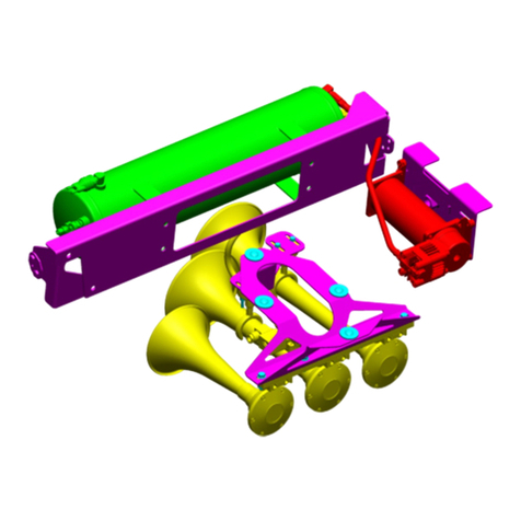
Kleinn Air Horns RPTR-OBA/734 User manual

RPTR-OBA/734
Installation Manual
REV: B (04/25/2022)
2
Table of Contents
1 Safety First ............................................................................................................................................ 4
2 Application Chart .................................................................................................................................. 5
2.1 Bolt-On Vehicle List....................................................................................................................... 5
2.2 Excluded Vehicles.......................................................................................................................... 5
2.3 Aftermarket Product Compatibility .............................................................................................. 5
3 Installation Overview ............................................................................................................................ 6
3.1 Kit Layout & System Location(s) ................................................................................................... 6
3.2 Install Process Outline................................................................................................................... 7
3.3 Approximate Installation Time...................................................................................................... 7
4 List of Tools & Supplies ......................................................................................................................... 8
4.1 Standard Tool List (Required) ....................................................................................................... 8
4.2 Special Tool List (Recommended)................................................................................................. 8
4.3 Shop Consumables List (Recommended)...................................................................................... 8
5 Parts List................................................................................................................................................ 9
5.1 Review Parts List ........................................................................................................................... 9
5.2 Pre-Packaged Electromechanical Kit Items................................................................................... 9
5.3 Pneumatic Components................................................................................................................ 9
5.4 Electrical Components ................................................................................................................ 10
5.5 Mounting Brackets......................................................................................................................11
5.6 Hardware .................................................................................................................................... 11
5.7 Special Parts ................................................................................................................................ 13
6 Bench Assembly .................................................................................................................................. 14
6.1 Install Air Fittings ........................................................................................................................ 14
6.1.1 Air Tank Fittings ..................................................................................................................14
6.1.2 1302 Quick Connect (On-Board Air).................................................................................... 14
6.1.3 INF-1 & Air Horns ................................................................................................................15
6.2 Tank Brackets..............................................................................................................................15
6.2.1 Rubber Trim ........................................................................................................................ 15
6.2.2 Tank Strap Installation ........................................................................................................ 16
6.3 Air Horn Driver Hardware ........................................................................................................... 18

RPTR-OBA/734
Installation Manual
REV: B (04/25/2022)
3
6.3.1 Rear Horn Bracket Preparation...........................................................................................18
6.3.2 Front Horn Bracket Preparation.......................................................................................... 18

7 On-Vehicle Installation........................................................................................................................19
7.1 Nut Plates & Tank/Compressor Bracket Installation .................................................................. 19
7.2 Rear Tank Bracket Installation ....................................................................................................22
7.3 Compressor Installation .............................................................................................................. 24
7.4 Tank Installation..........................................................................................................................25
7.5 Front Horn Bracket Installation................................................................................................... 27
7.6 Rear Horn Bracket Installation....................................................................................................31
7.7 Air Horn Installation....................................................................................................................34
8 Pneumatic Tubing Routing & Plumbing. .............................................................................................35
9 Electrical Wiring .................................................................................................................................. 36
10 Final Steps & Testing.......................................................................................................................38
10.1 Reconnect Vehicle Battery(s)...................................................................................................... 38
10.2 If removed, reinstall the fuse......................................................................................................38
10.3 Test Air Compressor.................................................................................................................... 38
10.4 Test Train Horns .......................................................................................................................... 38
10.5 Test Quick Connect Coupler........................................................................................................ 38
11 General Operation ..........................................................................................................................39
11.1 Compressor Operation................................................................................................................ 39
11.2 Horn Operation ........................................................................................................................... 39
12 Routine Maintenance ..................................................................................................................... 39
13 Warranty Information..................................................................................................................... 40
END OF TABLE OF CONTENTS

RPTR-OBA/734
Installation Manual
REV: B (04/25/2022)
4
1Safety First
Read manual thoroughly before starting installation of this kit. Verify that you have all parts listed, and
that you clearly understand the installation procedure. Contact Kleinn technical support with any
questions.
Installation of this kit requires moderate mechanical aptitude; seek professional help if you’re not
competent using hand tools in tight uncomfortable spaces and around possibly rusted and sharp vehicle
parts.
Before starting, obtain proper tools required to perform installation correctly, adequate lighting, eye
protection, hearing protection, (for operating train horns) and hand protection to guard against sharp
edges and metal burrs which may be present on kit parts and/or vehicle parts.
Throughout this manual the following words may be used; be aware of their meaning and application.
CAUTION: means damage could occur to vehicle or kit parts during or after installation.
WARNING: means injury could occur to you or others, including damage to vehicle or kit parts.
DANGER: means serious injury or death could occur to you or others during installation.
END OF SECTION

RPTR-OBA/734
Installation Manual
REV: B (04/25/2022)
5
2Application Chart
2.1 Bolt-On Vehicle List
RPTR-OBA/734 is a 100% direct bolt-on aftermarket product for the Ford Vehicles listed below. Every
effort has been made to verify fitment on these vehicles in their factory condition.
MODEL YEAR
MODEL
DRIVE
ENGINE
BODY
TRIM
2017-2020
F-150 RAPTOR
4WD
3.5L EcoBoost
SuperCrew
ALL
NOTE: Vehicle may require drilling holes for electrical ground points, wiring, switches, and on-
board air based on preference.
2.2 Excluded Vehicles
The following vehicles have been found to be incompatible with the designed kit:
MODEL YEAR
MODEL
DRIVE
ENGINE
BODY
TRIM
2017-2020
F-150 RAPTOR
4WD
3.5L EcoBoost
SuperCab
ALL
2.3 Aftermarket Product Compatibility
NOTE: Before installing this product on a vehicle with any aftermarket parts attached in regions shown
in this manual, thoroughly review this manual to verify necessary mounting points and overall space
exists. At the discretion of end-user/installer, included Brackets/components may require modifications
to attach to vehicles with aftermarket parts. THIS VOIDS THE KLEINN WARRANTY.
This kit has not been designed to work with the following aftermarket products:
•This kit has NOT been designed or tested for use with aftermarket power truck steps which
attach to the inside of the rocker panel.
•This kit has NOT been designed or tested for use with aftermarket truck steps, which attach to
the frame.
•This kit has NOT been designed or tested for use with aftermarket exhaust systems.
•This kit has NOT been designed or tested for use with aftermarket suspension systems.
NOTE: Review this manual in full before unpacking items to verify correct space and mounting
locations exist with your aftermarket product(s). To install this kit alongside your other aftermarket
product(s), modification to the included parts, your vehicle, or your aftermarket product(s) may be
required.
END OF SECTION

RPTR-OBA/734
Installation Manual
REV: B (04/25/2022)
6
3Installation Overview
3.1 Kit Layout & System Location(s)
This kit consists of the following components, located on vehicle as follows:
Item No. Component Vehicle Location
Install Time
(APPROXIMATE)
1
6450RC 150 PSI Waterproof
Compressor
Outer passenger side frame rail, in between
front/rear door
2+ Hours
2
3 Gallon Air Tank
Outer passenger side frame rail, under rear door
2+ Hours
3
Model 730 Demon Triple Train Horn
Outer driver side frame rail, under rear door
1-2 Hours
*4
Remote Quick-Connect Coupler
To be determined by installer
Up to 1 Hour
*Not Illustrated
Figure 1- Component Location Overhead View
Figure 2- Compressor Installed
Figure 3- Tank Installed

RPTR-OBA/734
Installation Manual
REV: B (04/25/2022)
7
Figure 4- Horns Installed
3.2 Install Process Outline
For person(s) with prior experience installing this kit, a reminder of the install steps is provided below:
1. Layout all components of kit
2. Assemble fittings to Air Tank, On-board Air Kit, Tire Inflation Kit & Air Horns
3. Pre-assemble & prepare brackets for installation
4. Install the nut plates
5. Install the compressor bracket
6. Install the forward tank bracket
7. Install the rear tank bracket
8. Install & connect the tank & compressor
9. Install the horn brackets (if applicable)
10. Install and plumb the air horns
11. Install and plumb the On-board air relocation kit
12. Route & connect the air tubing
13. Route and connect the wiring
14. Test the system
3.3 Approximate Installation Time
This kit is a multi-faceted product consisting of mechanical, electrical, and pneumatic components.
For a typical home mechanic, auto enthusiast, or technician installing this kit for first time; a professional
installation job with setup and testing of final product, is estimated to take:
•6-12 Hours
END OF SECTION

RPTR-OBA/734
Installation Manual
REV: B (04/25/2022)
8
4List of Tools & Supplies
4.1 Standard Tool List (Required)
1. Basic mechanic’s 3/8” drive socket sets with extensions
•Inch size sockets
•Metric size sockets
2. Basic mechanic’s combination wrenches (box/open-end)
•Inch size wrenches
•Metric size wrenches
3. Basic mechanic’s screwdriver set (Philips, Flat Head)
4. Diagonal cutter/wire cutter pliers
5. Wire strippers
6. Wire terminal crimpers
7. Slip-joint pliers
8. Vise grips or locking pliers
9. Small pry bar or large flat blade screwdriver
10. Utility knife
11. Magnetic retrieval tool
4.2 Special Tool List (Recommended)
1. 10-100 ft-lbs. torque wrench
2. 20-150 in-lbs. torque wrench
3. Multi-meter or 12V DC test light or equivalent
4. Trim panel tool, for removing wiring and body clips, when needed
4.3 Shop Consumables List (Recommended)
1. Quality electrical tape
2. Di-electric grease for electrical connections
3. Heat shrink tubing for electrical connections
4. Medium-strength thread-locker (i.e., Blue Loctite® PN 242) or equivalent
5. Low-strength thread-locker (i.e., Purple Loctite® PN 222) or equivalent
6. Black/Clear silicone for drilling holes in body
7. Sandpaper or wire brushes for installing ground wires
8. Extra plastic zip ties > 6” long
9. Extra NPT sealant (i.e., Kleinn Air Horn Juice, Teflon tape, etc.)
10. Touch-up paint for frame/chassis/body (i.e., primer or black epoxy)
11. Typical cleaning supplies
END OF SECTION

RPTR-OBA/734
Installation Manual
REV: B (04/25/2022)
9
5Parts List
This section should be printed to expedite the installation process.
5.1 Review Parts List
Unpackage and organize kit and verify all parts are included, as listed below. Contact Kleinn
support with any questions.
5.2 Pre-Packaged Electromechanical Kit Items
NOTE:Items in this section come in their own packages and may include additional items inside package.
Item No
Qty
Part Number
Description
Picture
1. 1 6450RC 150 PSI Air Compressor
2. 1 730 Model 730 Triple Train Horns
3. 1 1302L Remote Quick Connect Coupler Kit
4. 1 INF-1 Tire Inflation Kit
5.3 Pneumatic Components
Item No
Qty
Part Number
Description
Picture
5. 1 6353RT 2.8 Gallon Air Tank, 9 NPT Ports
6. 1 52835 Drain Valve, ¼” NPT
7. 1 52175 175 PSI Safety Valve, ¼” NPT

RPTR-OBA/734
Installation Manual
REV: B (04/25/2022)
10
8. 3 50040 Hex Plug, ¼” NPT
9. 1 51414L 90° Elbow Fitting,
¼” NPT to ¼” Compression
10. 1 51214L 90° Elbow Fitting,
¼” NPT to ½” Compression
11. 1 2151 Pressure Switch, ¼” NPT
12. 10 ft 25014 Black Air Tubing, ¼”
13. 1 JUICE Kleinn Air Horn Juice – Thread
Sealant
5.4 Electrical Components
Item No
Qty
Part Number
Description
Picture
14. 1 320 Terminator Horn Button
15. 1 WIRE KIT Complete wire kit w/ electrical
connectors & zip ties
16. 20 ft WIRE LOOM ¼” Split Wire Loom, Black
17. 10 ft WIRE LOOM 1/8” Split Wire Loom, Black

RPTR-OBA/734
Installation Manual
REV: B (04/25/2022)
11
5.5 Mounting Brackets
Item No
Qty
Part Number
Description
Picture
18. 1 RAPTOR-110 Compressor Bracket
19. 2 RAPTOR-202 Tank Strap
20. 2 RAPTOR-203 Nut Plate
21. 1 RAPTOR-210 Rear Tank Bracket
22. 1 RAPTOR-211 Front Tank Bracket
23. 1 RAPTOR-310 Rear Horn Mount
24. 1 RAPTOR-311 Front Horn Mount
5.6 Hardware
Item No
Qty
Description
Picture
H1. 4 Socket Head Cap Screw – ¼”-20, 1” Long
H2. 2 Phillips Pan Head Screw – ¼”-20, .75” Long

RPTR-OBA/734
Installation Manual
REV: B (04/25/2022)
12
H3. 4 Hex Bolt – 5/16”-18, 1” Long
H4. 4 Carriage Bolt (knurled) – 5/16”-18, .75” Long
H5. 6 Carriage Bolt (square neck) – 5/16”-18, 1.25” Long
H6. 1 Carriage Bolt (knurled) – 5/16”-18, 1” Long
H7. 4 Lock Washer – ¼”
H8. 15 Lock Washer – 5/16”
H9. 4 Flat Washer – ¼”, .63” OD
H10. 15 Flat Washer – 5/16”, .69” OD
H11. 4 Flat Washer – 5/16”, .88” OD
H12. 1 Fender Washer – 5/16”, 1.25” OD
H13. 11 Hex Nut – 5/16”-18
H14. 1 Clip-on Barrel Nut – M8 x 1.25
H15. * Hex Bolt – M8 x 1.25
H16. * Lock Washer – M8

RPTR-OBA/734
Installation Manual
REV: B (04/25/2022)
13
H17. * Flat Washer – M8, 16mm OD
H18. ** Compressor Mounting Hardware - Assorted
*Included inside Horn Box
**Included inside Compressor Box
5.7 Special Parts
Item No
Qty
Description
Picture
25. 2 Rubber Trim (wide “C”) – 9” Strip
26. 2 Rubber Trim (narrow “U”) – 9” Strip
END OF SECTION

RPTR-OBA/734
Installation Manual
REV: B (04/25/2022)
14
6Bench Assembly
Complete the following steps off vehicle to facilitate final installation.
6.1 Install Air Fittings
Gather the air fittings for installation on the following components (as applicable):
•Air Tank
•1302 Quick Connect Bracket
•INF-1 Inflator Kit
•Air Horns
Apply two drops of Item 13 (JUICE) to each male pipe thread before installation.
Hand-tighten each fitting, then further tighten ¼ to ½ turn as necessary to match the
fitting orientation shown in the below figures.
6.1.1 Air Tank Fittings
Attach air fittings to the tank per the below figure.
Figure 5- Tank Fitting Installation
6.1.2 1302 Quick Connect (On-Board Air)
1. Attach air fittings per the below figure.
2. Reference the 1302 Remote Quick Connect Instructions at Kleinn.com for more information.
Figure 6- 1302 Quick Connect Assembly

RPTR-OBA/734
Installation Manual
REV: B (04/25/2022)
15
6.1.3 INF-1 & Air Horns
1. Install the fittings (located in the INF-1 Bag) to the INF-1 kit.
For the following step, separate the medium air horn trumpet from the base as shown below.
2. Install the air valve onto the medium horn driver fitting with the direction of flow (arrow
indicator) pointed towards the air horn driver. The black housing should be oriented as shown
below.
Figure 7- Horn Solenoid Orientation
3. Install the supplied compression fitting onto the inlet port of the solenoid.
6.2 Tank Brackets
The following brackets & hardware are used in this step:
•Item 19 = RAPTOR-202 – Qty: 2
•Item 21 = RAPTOR-210
•Item 22 = RAPTOR-211
•Item H1, H7, H9 – Qty: 4 each
•Item 25 & 26 – Qty: 2 each
Note: Tank straps may come pre-bent, if so, skip steps 6.2.2 Step #3 – 6.2.2 Step #7
6.2.1 Rubber Trim
Trim item 25 & 26 to fit (if needed) and install onto RAPTOR-202 & RAPTOR-210, -211 as shown
in the following figure.

RPTR-OBA/734
Installation Manual
REV: B (04/25/2022)
16
Figure 8- Rubber Trim Installation
6.2.2 Tank Strap Installation
1. Take hardware H1, H7, & H9 and insert into the hole (NOT SLOT) of Item 19 (tank strap) in the
stacking order shown below.
Figure 9- Tank Strap Hardware Stacking Order

RPTR-OBA/734
Installation Manual
REV: B (04/25/2022)
17
2. Install onto the upper threads of the brackets (Item 21 & 22) as shown below.
Figure 10- RAPTOR-210 (Left) & -211 (Right) – Straps are shown pre-bent
3. If straps are not pre-bent, place Item 5 (Air Tank) onto the brackets RAPTOR-210 & -211 (Item 21
& 22).
4. Place hardware H1, H7, & H9 in the stacking order above, onto the slotted hole in the Tank strap
& form the strap to match the contour of the tank.
5. As you form the strap, align the fastener to the bottom threaded hole on the bracket and fasten
the strap & tank completely to the bracket.
6. Repeat for the second strap.
7. Once the straps are formed, Remove the lower fasteners and remove the tank. Set aside for
future use. Keep the upper fasteners in place, securing the straps to the brackets.

RPTR-OBA/734
Installation Manual
REV: B (04/25/2022)
18
6.3 Air Horn Driver Hardware
The following brackets & hardware are used in this step:
•Item 23 = RAPTOR-310
•Item 24 = RAPTOR-311
•Item H5, H8, H10, H13 – Qty: 6 each
6.3.1 Rear Horn Bracket Preparation
Loosely install hardware H5, H8, H10, H13 onto bracket RAPTOR-310 as shown in the below figure.
Verify hardware stacking and install locations match the figure.
Figure 11- Rear Bracket Horn Driver Hardware Installation
6.3.2 Front Horn Bracket Preparation
Loosely install hardware H5, H8, H10, H13 onto bracket RAPTOR-311 as shown in the below figure.
Verify hardware stacking and install locations match the figure.
Figure 12- Front Bracket Horn Driver Hardware Installation
END OF SECTION

RPTR-OBA/734
Installation Manual
REV: B (04/25/2022)
19
7On-Vehicle Installation
7.1 Nut Plates & Tank/Compressor Bracket Installation
The following brackets & hardware are used in this step:
•Item 18 = RAPTOR-110
•Item 20 = RAPTOR-203 – Qty: 2
•Item 22 = RAPTOR-211
•Item H2 – Qty: 2
•Item H3, H8, H10 – Qty: 4 each
1. Thread H2 into RAPTOR-203 approximately halfway (REF. Below).
2. Thread Qty: 1 H3 approximately halfway, into left or right hole of RAPTOR-203 temporarily as
shown below.
Figure 13- Nut Plate Preparation – Step 1 (Left), Step 2 (Right)
3. Locate 2 oval holes on passenger side frame rail in-between the front & rear door as shown.
Figure 14- Raptor-203 Install Location

RPTR-OBA/734
Installation Manual
REV: B (04/25/2022)
20
4. Use H3 as a handle to insert RAPTOR-203 into the oval frame rail holes & secure by tightening
H2 as shown below.
Note: Ensure RAPTOR-203 holes are parallel to the floor and are not obstructed by the frame.
Figure 15- RAPTOR-203 Installation
5. Remove the H3 from both RAPTOR-203’s to be reused.
6. Take Qty: 2 of each H3, H8, H10 in the below stacking order and install RAPTOR-110 onto the
front-most RAPTOR-203 as shown below.
Figure 16- RAPTOR-110 Hardware Stacking Order
Table of contents
Other Kleinn Air Horns Horn manuals